Table of Contents
Advertisement
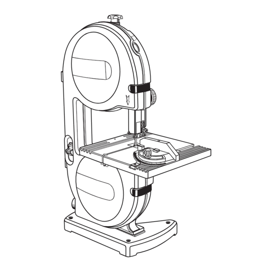
OPERATOR'S MANUAL
9 in. BAND SAW
Model No.
315.214770
WARNING
: To reduce the risk of injury,
the user must read and understand the
operator's manual before using this product.
Customer Help Line: 1-800-932-3188
Sears, Roebuck and Co., 3333 Beverly Rd., Hoffman Estates, IL 60179 USA
Visit the Craftsman web page: www.sears.com/craftsman
983000-577
8-04
Save this manual for future reference
Advertisement
Table of Contents

Related Manuals for Craftsman 315.214770


Summary of Contents for Craftsman 315.214770
- Page 1 Customer Help Line: 1-800-932-3188 Sears, Roebuck and Co., 3333 Beverly Rd., Hoffman Estates, IL 60179 USA Visit the Craftsman web page: www.sears.com/craftsman Save this manual for future reference 983000-577 8-04...
-
Page 2: Table Of Contents
Exploded View and Parts List............................24 n Parts Ordering/Service ............................. Back Page WARRANTY FULL ONE YEAR WARRANTY ON CRAFTSMAN TOOL CRAFTSMAN tool fails to give complete satisfaction within one year from the date of purchase, RETURN IT TO If this THE NEAREST SEARS STORE OR SEARS SERVICE CENTER IN THE UNITED STATES, and Sears will repair it, free of charge. -
Page 3: General Safety Rules
GENERAL SAFETY RULES WARNING: n MAINTAIN TOOLS WITH CARE. Keep tools sharp Read and understand all instruc- and clean for best and safest performance. Follow tions. Failure to follow all instructions listed below, instructions for lubricating and changing accessories. may result in electric shock, fire and/or serious personal injury. - Page 4 GENERAL SAFETY RULES n AVOID AWKWARD OPERATIONS AND HAND PO- n BEFORE CHANGING THE SETUP, REMOVING COV- SITIONS where a sudden slip could cause your hand ERS, GUARDS, OR BLADES, unplug the saw and re- to move into the blade. ALWAYS make sure you have move the switch key.
-
Page 5: Symbols
SYMBOLS Some of the following symbols may be used on this tool. Please study them and learn their meaning. Proper interpretation of these symbols will allow you to operate the tool better and safer. SYMBOL NAME DESIGNATION/EXPLANATION Volts Voltage Amperes Current Hertz Frequency (cycles per second) -
Page 6: Save These Instructions
SYMBOLS The following signal words and meanings are intended to explain the levels of risk associated with this product. SYMBOL SIGNAL MEANING DANGER: Indicates an imminently hazardous situation, which, if not avoided, will result in death or serious injury. WARNING: Indicates a potentially hazardous situation, which, if not avoided, could result in death or serious injury. -
Page 7: Electrical
ELECTRICAL EXTENSION CORDS SPEED AND WIRING The no-load speed of this tool is approximately 3,000 Use only 3-wire extension cords that have 3-prong grounding plugs and 3-pole receptacles that accept the sfpm. This speed is not constant and decreases under tool’s plug. -
Page 8: Glossary Of Terms
GLOSSARY OF TERMS Anti-Kickback Pawls (radial arm and table saws) Non-Through Cuts A device which, when properly installed and maintained, Any cutting operation where the blade does not extend is designed to stop the workpiece from being kicked back completely through the thickness of the workpiece. toward the front of the saw during a ripping operation. -
Page 9: Features
FEATURES PRODUCT SPECIFICATIONS Blade Width..........1/8 in. to 3/8 in. Input ......120 Volt, 60Hz, AC Only, 2.3 Amps Blade Length ............59-1/4 in. No Load Speed ..........3,000 SFPM Frame to Blade Capacity..........9 in. Overall Dimensions ... 19-1/2 in. x 12-1/2 in. x 28 in. Cutting Thickness Capacity ........ - Page 10 FEATURES KNOW YOUR BAND SAW Saw Blade See Figure 2. The band saw comes with a standard saw blade installed. Two extra saw blades are included with the loose parts. Before attempting to use this product, familiarize yourself with all operating features and safety rules. Saw Table The band saw has a square 11-3/8 in.
-
Page 11: Tools Needed
TOOLS NEEDED The following tools (not included) are needed for checking adjustments of the saw or for installing the blade: ADJUSTABLE WRENCH COMBINATION SQUARE PHILLIPS SCREWDRIVER Fig. 3 LOOSE PARTS LIST The following items are included with the tool: 3 mm Hex Key..............1 Table Lock Handle............ -
Page 12: Assembly
ASSEMBLY UNPACKING This product requires assembly. n Carefully lift saw from the carton and place it on a level work surface. NOTE: This tool is heavy. To avoid back injury, lift with your legs, not your back, and get help when needed. n Inspect the tool carefully to make sure no breakage or TABLE ALIGNING... - Page 13 ASSEMBLY CLAMPING BAND SAW TO WORKBENCH n Insert the washer on the threaded end of the table lock handle. The table lock handle is spring loaded and See Figure 7. is released by pulling the handle away from the saw If the band saw is to be used as a portable tool, it is housing.
- Page 14 ASSEMBLY ADJUSTING BLADE GUIDE ASSEMBLY See Figure 8. WARNING: To avoid personal injury, maintain proper adjustment of blade tension, blade guides, and thrust bearings. BLADE GUIDE KNOB To prevent the blade from twisting or breaking, the blade guide assembly should always be set approximately 1/8 BLADE GUIDE in.
-
Page 15: Adjusting Blade Tension
ASSEMBLY ADJUSTING BLADE TENSION NOTE: The blade may need to be turned inside out if the teeth are pointing in the wrong direction. Hold the See Figures 10 - 11. blade with both hands and rotate it inward. n Turn off and unplug the saw. Remove the switch key. n With the teeth of the blade toward the front of the saw n Before using the band saw, turn the blade tension knob and facing downward, place the blade through the... - Page 16 ASSEMBLY SQUARING THE SAW TABLE TO THE BLADE BLADE See Figure 13. TENSION KNOB n Remove the blade guard by loosening the two set screws with the 4 mm hex key. n Turn the lock lever counterclockwise to unlock the blade guide assembly.
- Page 17 ASSEMBLY ADJUSTING THRUST BEARINGS, BLADE n Adjust the thrust bearings first. Using the 4 mm hex key, loosen the thrust bearing screw. GUIDE SUPPORT, AND BLADE GUIDES See Figures 14 - 16. n Move the thrust bearing to within 1/64 in. of the blade. Tighten the thrust bearing screw securely.
-
Page 18: Operation
ASSEMBLY BLADE GUIDE To Adjust Blade Guides: ASSEMBLY The blade guides help keep the blade from twisting and binding. The blade will be ruined if the blade teeth hit the blade guides while using the band saw. The set of teeth and the sharpened edge of teeth will be damaged by hit- ting the blade guides. - Page 19 OPERATION REMOVING JAMMED MATERIAL n Avoid awkward operations and hand positions where a sudden slip could cause serious injury from contact Never remove jammed cutoff pieces until the blade has with the blade. Never place hands in blade path. come to a full and complete stop. n Use extra supports (tables, saw horses, blocks, etc.) n Place the switch in the OFF position, remove the when cutting large, small, or awkward workpieces.
- Page 20 OPERATION BEFORE LEAVING THE SAW See Figure 17. n Wait until the saw has come to a full and complete stop. n Place the switch in the OFF position, remove the switch key from the switch assembly. Store key in a safe place.
-
Page 21: Maintenance
MAINTENANCE TIRES WARNING: When servicing, use only identical replacement parts. Use of any other part may create Cleaning tires: a hazard or cause product damage. n Pitch and sawdust accumulates on tires and needs to be removed with a fine wire brush or a piece of wood. Do WARNING: not use a sharp knife or any kind of solvent. - Page 22 MAINTENANCE MOTOR/ELECTRICAL TIRE LOWER WASHER n Frequently vacuum or blow out sawdust from the mo- SCREW WHEEL BRUSH tor. WARNING: If the power cord is worn, cut or dam- aged in any way, have it replaced immediately by a qualified service technician. Failure to do so could result in serious personal injury.
-
Page 23: Troubleshooting
TROUBLESHOOTING PROBLEM CAUSE SOLUTION Motor will not run. 1. Problem with On-Off switch or 1. Have worn parts replaced before power cord. using band saw again. 2. Motor defective. 2. Do not attempt any repair. Have tool repaired by a qualified service technician. -
Page 24: Exploded View And Parts List
NOTES NOTES... - Page 25 CRAFTSMAN BAND SAW – MODEL NO. 315.214770 FIGURE A...
- Page 26 CRAFTSMAN BAND SAW – MODEL NO. 315.214770 The model number will be found on a plate attached to the housing. Always mention the model number in all correspondence regarding your band saw or when ordering repair parts. SEE BACK PAGE FOR PARTS ORDERING INSTRUCTIONS...
- Page 27 CRAFTSMAN BAND SAW – MODEL NO. 315.214770 The model number will be found on a plate attached to the housing. Always mention the model number in all correspondence regarding your band saw or when ordering repair parts. SEE BACK PAGE FOR PARTS ORDERING INSTRUCTIONS...
- Page 28 CRAFTSMAN BAND SAW – MODEL NO. 315.214770 The model number will be found on a plate attached to the housing. Always mention the model number in all correspondence regarding your band saw or when ordering repair parts. SEE BACK PAGE FOR PARTS ORDERING INSTRUCTIONS...
- Page 30 CRAFTSMAN BAND SAW – MODEL NO. 315.214770 The model number will be found on a plate attached to the housing. Always mention the model number in all correspondence regarding your band saw or when ordering repair parts. SEE BACK PAGE FOR PARTS ORDERING INSTRUCTIONS...
- Page 31 CRAFTSMAN BAND SAW – MODEL NO. 315.214770 The model number will be found on a plate attached to the housing. Always mention the model number in all correspondence regarding your band saw or when ordering repair parts. SEE BACK PAGE FOR PARTS ORDERING INSTRUCTIONS...
- Page 32 Get it fixed, at your home or ours! Your Home For repair – in your home – of all major brand appliances, lawn and garden equipment, or heating and cooling systems, no matter who made it, no matter who sold it! For the replacement parts, accessories and owner’s manuals that you need to do-it-yourself.