Table of Contents
Advertisement
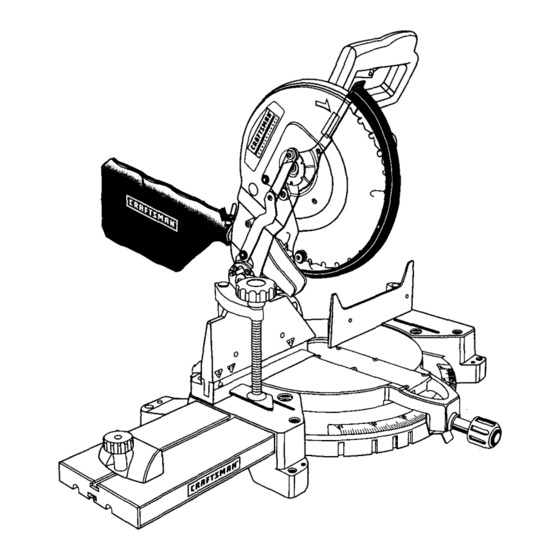
Operator's Manual
12 in. COMPOUND
MITER SAW
Double Insulated
Model No.
315.212240
Save this manual
for
future reference.
,_
CAUTION:
Read and follow
all Safety Rules and Operating
Instructions
before
first use of
this product.
Customer
Help Line: 1-800-932-3188
• Safety
• Features
• Adjustments
• Operation
• Maintenance
• Parts List
Sears,
Roebuck
and
Co.,
3333
Beverly
Rd.,
Hoffman
Estates,
IL 60179
USA
Visit
the Craftsman
web
page:
www.sears.com/craftsman
C _
I1_
IbD ll,I
972000-986
4-02
Advertisement
Table of Contents

Related Manuals for Craftsman 315.212240


Summary of Contents for Craftsman 315.212240
- Page 1 Safety Rules and Operating • Operation Instructions before first use of • Maintenance this product. • Parts List Customer Help Line: 1-800-932-3188 Sears, Roebuck Co., 3333 Beverly Rd., Hoffman Estates, IL 60179 IbD ll,I Visit the Craftsman page: www.sears.com/craftsman 972000-986 4-02...
- Page 2 • Table of Contents ..............................• Warranty and Introduction ........................... • Rules for Safe Operation ..........................• Glossary of Terms ..............................• Product Specifications and Unpacking ........................ • Accessory List ..............................• Loose arts List and Tools Needed ........................• Labels .................................
- Page 3 The purpose of safety symbols is to attract your attention to possible dangers. The safety symbols, and the explanations with them, deserve your careful attention and understanding. The safety warnings do not by themselves eliminate any danger. The instructions or warnings they give are not substitutes for proper accident prevention measures.
- Page 4 • USE THE PROPER EXTENSION CORD. Make breakage of parts, saw stability, mounting and any sure your extension cord is in good condition. Use other conditions that may affect its operation. A only a cord heavy enough to carry the current your damaged part must be properly repaired or re- product will draw.
- Page 5 Sears store or repair center. the workpiece. Allow motor to come up to full speed before starting cut. • WHEN SERVICING, use only identical Craftsman • MAKE SURE THE MITER TABLE AND SAW replacement parts. Use of any other parts may ARM (BEVEL FUNCTION) ARE LOCKED IN create a hazard or cause product damage.
- Page 6 • ALWAYS TURN OFF THE SAW before discon- WARNING: Some dust created by power necting it to avoid accidental starting when recon- sanding, sawing, grinding, drilling, and other construction activities contains chemicals known necting to power supply. NEVER leave the saw unattended while connected to a power source.
- Page 7 Blade Diameter 12 in. Cutting Capacity with Miter at 0°/Bevel 0°: Blade Arbor 5/8 in. width x height 7-7/8 in. x 2-1/2 in. No Load Speed 4000 RPM Cutting Capacity with Miter at 45°/Bevel 0°: Rating 15 Amperes width x height 5-1/2 in.
- Page 8 Thefollowing accessories a reincluded withyourCompound M iterSaw: • Clamp Extension R od(1) • DustBag • Phillips Screw(4) • TableExtensions ( 1) • TableClamp Bracket • Support R od(2) • Extension C lamp Bracket • StopBlock • Square Head Bolt(1) • StopBlockKnob •...
- Page 9 The following items are included with your Compound Miter Saw: • Saw Blade - 12 in. • 6 mm Hex Key Wrench • Miter Lock Handle • 10 mm Hex Key Wrench • Dust Guide • Laser Guide • Blade Wrench •...
- Page 10 12 inch Compound Miter Saw DOUBLE INSULATED 4,000 RPM 120 VOLTS60 ltz AC ONLY15 A I _WARNING J WHEN SERVICING,USEONLY iDENTICAL cRAFTSMAN REPLACEMENT PARTS. E 67 MODEL 315.212240 seR. NO. C_US MADE IN TAIWA N SEARS.
- Page 11 KNOW YOUR COMPOUND MITER CUTTING CAPACITIES See Figure 3. When the miter angle (miter table) is set at 0 ° and Before attempting to use your saw, familiarize your- the bevel angle is set at 0°: self with all operating features and safety require- Your saw will cut materials up to: ments.
- Page 12 CARRYINGHANDLE SPINDLE LOCK BUTTON See Figure 5. See Figure 4. A spindle lock button has been provided for locking For convenience when carrying or transporting your the spindle which keeps the blade in your saw from miter saw from one place to another, a carrying handle has been provided on top of the saw arm as rotating.
- Page 13 30 in. POSITIVE STOPS ON MITER TABLE 21-3/4in. Positive stops have been provided at 0 °, 15°, 22-1/2 °, 4-1/8in. I 31.62 °, and 45 ° on both the left and right side of the miter table. BEVEL LOCK KNOB -;,,,- The bevel lock knob securely locks your compound 1/2 in.
- Page 14 TO INSTALL BLADE WARNING: To prevent accidental starting that could cause possible serious personal injury, See Figures 10, 11, and 12. assemble all parts to your saw before connecting it to power supply. Saw should never be WARNING: A 12 in. blade is the maximum connected to power supply when you are blade capacity of your saw.
- Page 15 • Wipe a drop of oil onto inner blade washer and LOWER outer blade washer where they contact the blade. ARROW BLADEGUARD PHILLIPS WARNING: If inner blade washer has been SCREW removed, replace it before placing blade on spindle. Failure to do so could cause an accident BLADE since blade will not tighten properly.
- Page 16 FENCE Note: Many of the illustrations in this manual show MITERTABLE only portions of your compound miter saw. This is intentional so that we can cleady show points being made in the illustrations. Never operate your saw without all guards securely in place and in good operating condition.
- Page 17 FENCE SQUARING THE SAW BLADE TO THE FENCE FRAMING SQUARE See Figures 17 - 20. • Unplug your saw. WARNING: Failure to unplug your saw could result in accidental starting causing possible serious personal injury. • Pull the saw arm all the way down and engage the lock pin to hold the saw arm in transport position.
- Page 18 SQUARING THE BLADE TO THE • If the top or bottom of the saw blade angles away MITER TABLE from the square as shown in figures 22 and 23, adjustments are needed. See Figures 21-24. • Unplug your saw. FENCE WARNING: Failure to unplug your saw could result in accidental starting causing possible...
- Page 19 TRAVEL PIVOT ADJUSTMENT BEVELLOCK • The saw arm should rise completely to the up , KNOB position by itself. • If the saw arm does not raise by itself or if there is POSITIVESTOP play in the pivot joints, have saw repaired by a ADJUSTMENT qualified service technician at your nearest Sears 45°...
- Page 20 CuI"rlNG WITH YOUR COMPOUND MITER SAW WARNING: When using a work clamp or C-clamp to secure your workpiece, clamp workpiece on one side of the blade only. The workpiece must remain free oh one side of the BEVEL blade to prevent the blade from binding in LOCKKNOB workpiece.
- Page 21 BEVEL See Figures 27 and 28. A bevel cut is made by cutting across the grain of the Workpiece with the blade angled to the workpiece. A straight bevel cut is made with the miter table set at the zero degree pos!tion and the blade set at an angle STRAIGHT between 0 °...
- Page 22 BEVELCUT • When cutting long pieces of lumber or molding, support the opposite end of the stock with a roller stand or with a work surface level with the saw table. • Align the cutting line on the workpiece with the edge of saw blade.
- Page 23 TO MAKE A COMPOUND CUT WITH YOUR • Place the workpiece flat on the miter table with one edge securely against the fence. If the board is MITER SAW: warped, place the convex side against the fence. If • Pull out the lock pin and lift saw arm to its full the concave edge of a board could collapse on the height.
- Page 24 • Before turning on the saw, perform a dry run of the cutting operation just to make sure that no problems will occur when the cut is made. • Grasp the saw handle firmly, then squeeze the switch trigger. Allow several seconds for the blade to reach maximum speed.
- Page 25 CUTTING COMPOUND MITERS To aid in making the correct settings, the compound angle setting chart below has been provided. Since com- pound cuts are the most difficult to accurately obtain, tdal cuts should be made in scrap material, and much thought and planning made, prior to making your required cut.
- Page 26 CUTTING CROWN MOLDING LAYING MOLDING FLAT ON THE MITER TABLE Your compound miter saw does an excellent job of See Figure32. cutting crown molding. In general, compound miter saws do a better job of cutting crown molding than To use this method for accurately cutting crown any other tool made.
- Page 27 Bevel Angle Typeof Cut Setting Leftside,insidecorner 1.Topedgeofmolding against f ence 33'85° 2. Mitertablesetright31.62 ° 3. Save left end of cut Right side, inside corner 1. Bottom edge of molding against fence 33"85° 2, Miter table set left 31.62 ° 3. Save left end of cut Left side, outside corner 1.
- Page 28 OPERATION MOUNTING THE LASER GUIDE See Figure 37. See Figure 36. The laser guide will generate a red colored line on the • Unplug your saw. work surface when the saw blade is spinning above 500 rpm. The red laser line will appear as a broken WARNING: Failure to unplug your saw could line on the workpiece when the blade assembly is in...
- Page 29 CHANGING THE BATTERIES See Figure 38. • Unplug your saw. LASERGUIDE ". SUPPORT WARNING: Failure to unplug your saw could result in accidental starting causing possible serious personal injury. Remove the laser guide from the saw. Lay laser guide on a flat surface with the two phillips screws facing upward.
- Page 30 CORDS WARNING: When servicing, use only identical Craftsman replacement parts. Use of any other The use of any extension cord will cause some loss of part may create a hazard or cause product power. To keep the loss to a minimum and to prevent damage.
- Page 31 Your saw has externally accessible brush assemblies WARNING: To ensure safety and reliability, repairs -- with the exception of the externally that should be periodically checked for wear. accessible brushes should be performed by a Proceed as follows when replacement is required: qualified service technician...
- Page 32 TABLE EXTENSION TO Level the Miter Saw: See Figures 41, 42, and 43. • Loosen wing nut. The table extension can be used on either the right or • Place a level or cther straight object across the left side of your miter saw. To assemble and install miter saw base and table extension.
- Page 33 STOP BLOCK WORK CLAMP ASSEMBLY See Figures 41 and 45. See Figures 43 and 44. WORKCLAMP ASSEMBLY PHILLIPS SCREW CLAMP _ CLAMP SUPPORT PHILLIPS SCREW STOP BLOCK KNOB TABLE SUPPORT EXTENSION RODS .STOP HOLESFOR CLAMP BLOCK LR(TENSION ROD The stop block is useful as a stop for cutting multiple pieces to the same length, Fig.
- Page 34 CLAMPINGWORKPIECE TO THE FENCE CLAMPING WORKPIECE TO THE SAW TABLE • Insert the grooved end of the clamp extension rod • Insert the grooved end of the clamp extension rod as far as it will go into the front hole of the clamp into the back, top hole of the clamp support.
- Page 36 CRAFTSMAN COMPOUND MITER SAW - MODEL NUMBER 315.212240 Figure A...
- Page 37 CRAFTSMAN COMPOUND MITER SAW - MODEL NUMBER 315.212240 number in all correspondence regarding your COMPOUND MITER SAW or when ordedng repaJr parts. The model number wdl be found on a plate attached to the motor housing Always mention the model...
- Page 38 CRAFTSMAN COMPOUND MITER SAW - MODEL NUMBER 315.212240 [j.J°l _._"_" ,f21 FigureB...
- Page 39 CRAFTSMAN COMPOUND MITER SAW- MODEL NUMBER 315.212240 COMPOUND MITER SAW or when ordering repasrparts. The model number wdl be found on a plate attached to the motor housing. Always mention the model number in all correspondence regarding your SEE BACK PAGE FOR PARTS ORDERING...
- Page 40 CRAFTSMAN COMPOUND MITER SAW- MODEL NUMBER 315.212240 SEE NOTE"A" _.15 7 .'_ "\ /" i" ° Note: ForLaser Guiderepair or °i ° replacement, c ontactyour nearest Sears Service Center Li I Laser J Guide FigureC...
- Page 41 CRAFTSMAN COMPOU ND MITER SAW - MODEL NUMBER 315.212240 The model number will be found on a plate attached to the motor housing. Always mention the model number in all correspondence regarding your COMPOUND MITER SAW or when ordering repair parts.
- Page 42 Get it fixed, at your home or ours'! For repair of major brand appliances in your own home... no matter who made it, no matter who sold it! 1-800-4-MY-HOM E sM Anyt,me, day or n,ght (1-800-469-4663) www.sears.com To bring in products such as vacuums, lawn equipment and electronics for repair, call for the location of your nearest Sears Parts &...