Table of Contents
Advertisement
OPERATOR'S
MANUAL
I CRRFTSMRN" I
PRO
FES
S
i
O
NAL
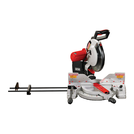
12 in. COMPOUND
MITER SAW
DOUBLE INSULATED
Model No.
315.212350
_k
WARNING: To reduce the risk of injury,
the user must read and understand the
operator'smanual before using this product.
Customer
Help Line: 1-800-932-3188
Bears, Roebuck and Co., 3333 Beverly Rd., Hoffman Estates, IL 60179 USA
Visit the Craftsman web page: www.sears.corn/craftsman
983000-550
Save this manual
for future
reference
9-04
Advertisement
Table of Contents

Related Manuals for Craftsman 315.212350


Summary of Contents for Craftsman 315.212350
- Page 1 Customer Help Line: 1-800-932-3188 Bears, Roebuck and Co., 3333 Beverly Rd., Hoffman Estates, IL 60179 USA Visit the Craftsman web page: www.sears.corn/craftsman 983000-550 Save this manual for future reference...
-
Page 2: Table Of Contents
ONE YEAR FULL WARRANTY ON CRAFTSMAN TOOL If this Craftsman tool fails due to a defect in materialor workmanshipwithin one year from the date of purchase, CONTACT THE NEAREST OEARS PARTS & REPAIR CENTER at 1-800.-4-MY-HOME _ and Sears wi(fmpafr it, free of charge. - Page 3 • SECURE WORK. Use clamps or a vise to hold work WARNING: Road and understand all Ir_struc- tlons. Failure to follow all fnstructions listed below, when practical it's safer than uslng your hand and may resultin eiectdc shock, fire and/or serious frees both handsto operate tool.
- Page 4 • USE ONLY CORRECT BLADES. Do not use blades • INSPECT TOOL CORDS PERIODICALLY. If damaged, with Incorrect size holes. Never use bladewashers or have repairedby a qualified service technician at blade bolts that are defective or incorrect.The maxi- an authorized servicefacility,The conductorwith insulationhaving an outer surface that is greenwith mum blade capacity of your saw is 12 in.
- Page 5 • NEVER hand hold a workplace that is too small to be • ALWAYS STAY ALERT[ Do not allow familiarity(gained clamped. Keep hands clear of the cutting area. from frequent use of your saw) to cause a careless mistake. ALWAYS REMEMBER that a carelessfraction •...
-
Page 6: Symbols
Some ofthe following symbolsmay be used on this tool. Please study them and learn their meaning, Proper interpretationof these symbolswill allow you to operate the tool better and safer, SYMBOL NAME DESIGNATION/EXPLANATION Volts Voltage Amperes C_rrest Hertz Frequency(cyclesper second) Watt Power MinUtes Time... - Page 7 The following s ignal words andmeanings are intendedto explain the levels of risk associated with this product. SYMBOL SIGNAL MEANING Indicatss an imminently hazardous situation, Which, if not avoided, w_l DANGER: resultin death or serious injury. Indicates a potentiallyhazardous s_uation, which, if not avoided, could WARNING: resultIn death or seriousInjury.
-
Page 8: Electrical
DOUBLEINSULATION EXTENSION CORDS Double insulationis a concept in safety in electric power When usinga powertool at a considerabledistance from tools, which eliminates the need for the usual_ree-wim a power source, be sure to use an extensioncord that has grounded power cord, All exposed metal parts are the capacity to handle the currentthe toolwilt draw.An Isolated from the Internalmetal motor componentswith undersizedcord will cause a drop In line voltage, resulting... - Page 9 Anti-Rlcld_aok Pawls Irad_al arm and table saws) Non-Through Cuts A devisewh)ch, when propertyInatalledand ma)ntalned, Any cutting operationwhere the blade does not extend is designed to stop the workpiece from being kicked back completelythroughthe thickness of the workplace. toward the front of the saw during a rippingoperation. Push Blocks and Push Sticks A.Vbor Devices used to feed the workpiece throughthe saw...
- Page 10 PRODUCTSPECIFICATIONS Blade Diameter ......12 In. Cutting Capacityw'rthMiter at 0"/Bevel 0°: Maximum nominal lumber sizes:....2 x 8, 4 x 4 BLade Arbor ....... 5/8 in, Cuttlng Capacltywith Miter at 45°/Bevel 0°: No Load Speed ......4,000/rain, Maximum nominallumber sizes: ......2 x 6 input ....
- Page 11 SPINDLE LOCK BUTTON KNOW YOUR COMPOUND MITER See Figure 1, See Figure 3. A spindlelock button has been provided for lockingthe Before attempting to use this product, familiarizeyourself spindlewhich keeps the blade in your saw from rota_ng. wffh art operatingfeatures and safety rules. Depressand hold the lock buttonwhile installing,chang- 15 AMP MOTOR ing, or removingblade.
- Page 12 LASERTRAC LASER GUIDE SLIDING MITER FENCE For more accurate cuts, a LaserTrec laser guide is Hold the workplace securelyagainst the miter fence when included with your miter saw. When used properly,the making all cuts. The s_k_ing feature allows both fences 0eft laser guide makes accurate, precisioncutting simpleand and right)to be moved when making bevel or compour_d easy.
- Page 13 The following Items are included with your Compound Miter Saw: • Dust Bag • Work Clamp • Dust Guide • Blade Wrench • Outer BladeWasher • Table Extensions (2) • Boit • Clamp Bracket • Clamp Bracket Bolt • Hex Key (3), 4 mm, 5 mm and B mm •...
-
Page 14: Assembly
UNPACKING ,_1 WARN|NG: Do not attempt to modify thistool or create accessoriesnot recommended for use This product requiresassembly. with this tool. Any such alterationor modification is • Carefullylift saw from the cartonby the carryinghandle misuse and could result In a hazardouscondition and the saw base, and place it on a level work surface. - Page 15 As mentioned previously,the saw has been factory assembled and adjusted. MITER LOCK HANDLE See Figure 8, Cut the tie-wraps holding the saw arm and the miter rock EXHAUST In place. To Instal[ the miter lookhandle, place the thread~ PORT ed stud into the threaded hole in the controlerm. Turn clockwiseto tighten.
- Page 16 TABLEEXTENSIONS BASE See Figures 11 - 12. TABLE Table extensions can be Installed in either the left or the EXTENSION fight side of the base. To Instalh • Insertthe ends of the table extensionsintothe holesin the side of the base and adjustthe extensionsto the desired length.
-
Page 17: Operation
_lb WARNING: When using the work clamp with the stop block, installthe clamp on the same side as the stop block. Thiswill ellmlnatethe posslb(tityof tmp- p]ng the workplece, resulting In the saw blade and workpiece kicking up. Failureto heed this warning can resultin sedous personalInjury, STOP BLOCK... - Page 18 • Unplug the saw. LOWER BLARE • Loosen phillipsscrew on the blade bolt cover until GUARD BRACKET blade boll cover can be raised. • Gently raise the lower blade guard bracket, releasing PHILLIPS lower blade guard from notch so that lower blade g_xard and blade bolt cover can be rotated up and back to expose the blade bolt.
- Page 19 MOUNTING THE LASER GUIDE ALIGNING THE LASER GUIDE LINE See Figure 19. See Figure20. Unplug the sew. The laser guide wit] generatea red coloredline on the work surfacewhen the b}adeis spinningabove 500 rpm. See "ToInstall Blade" on page 17 in the Assemb/yssct[on The red laser line will appear as e broken line on the of this operator's manual.
-
Page 20: Adjustments
NOTE: Many oftheillustrations inthismanual show only FRAMING FENCE MITER TABLE porttons o fthecompound miter s aw. T hisIsIntantEonal SQUARE thatwecanclearly show points being made in the illustrations.Never operate your saw without all guards securely In grace and rn good operating condition. SQUARING THE MITER TABLE TO THE... - Page 21 SQUARING THE SAW BLADE TO THE FENCE See Figures25 - 28, BLADE • Unplugthe saw. • Pull the saw arm all the way down and engage the look pin to hold the saw arm in transportposition, • Loosenthe miter lock handle, •...
- Page 22 SQUARING THE BLADE TO THE MITER TABLE See Figures29 - 31. • Unplug the saw. FENCE • Pull the saw arm all the way down and engage the 1ock pin to hold the saw arm in transport position, • Loosen the miter lock handle. •...
- Page 23 This caw hasthree scale indicators,two on the bevel scale and one on the miter scale. After squadng adjust- ments have been made, it may be necessaryto loosen the indicator screws and reset them to zero. FENCE • BLADE MITER COMBINATION SQUARE TABLE VIEWOFflLADE NOTSQUARE WITHMITER...
- Page 24 NOTE: Always check for interference between the blade • Tighten the miter lock handle securely. and the silding miter fence BEFORE attempting to make a cut. Some compound miter cuts rsquim the sliding miter _1. WARNING: To avoid serious personalinjury,always tighten the miter lock handle securelybefore making fence to be moved or completely removed before making e cut.
- Page 25 TO BEVEL CUT • Once the saw arm has been set at the desired angle, securely tighten the bevel lock knob. See Figures34.35. • Place the workpiece fiat on the miter table with one A bevel cut is made by cutting across the grain of the edge saCuTely against the fence, if _hs board is warped, workpiece with the blade angled to the workpiece.
- Page 26 TO MAKE A COMPOUND MITER • Recheck miter angle setting.Make a test cut in scrap material. A compound miter cut is a cut made usinga miter angle •PIsce the workplace flat on the rarer table with one and a bevel angle at the same time, This type of cut Is edge security againstthe fence.
- Page 27 SUPPORT LONG WORKPIECES See Figure 38. Longworkpieces need extra supports. Supportsshould be placed along the workpiece so it does not sag. The support should let the workplece lay f/at on the baee of the saw and work table dudng the cutting operation. Use the optional work clamp or a C-clamp to secure the workpiece.
- Page 28 CUTrlNG COMPOUNDMITERS To aid in making the correct se_ngs, the compoundangle se_ng chart below has been provided.Since compound cuts are the mo_t difficutt to accuratety obtain, trfatcuts shourdbe made in scrap materiat, and much thoughtand ptanning made, priorto making your required cut. NUM-"-L., ,Jr o,_=,= PITCH ol=slo...
- Page 29 CU'I'I'ING CROWN MOLDING When settingthe bevel and miter angles for compound miters, rememberthat the settingsare interdependent; The compound miter sew does an excellentJobof cut- changing one angle changes the other angleas well. ting crown molding. In general, compound miter eaws do a better Jobof cuffing crown molding than any othertool Keep in mind that the angles for crown moldingsare very made,...
- Page 30 molding. Also mostwalls do not have angles of exactly 90",therefore,you will need to fine tune your settings. When cutting crown molding by this method the bevel angte should be set at 0".The miter anglo shouldbe set at 45"either right or left, dopondingon the desired cut for the sppLLcation.
- Page 31 MARIOHGS OH THROAT PLATE WRONG CUTTING WARPED MATERIAL Fig. 44 See Figures 43 - 44. When cuttingwarped material, always make sure It Is WARN,|NG: To avoid a k_c_d_ack _ d to avoid positionedon the miter table with the convex side serious personaliniury,never positionthe concave againstthe fence as shown in f_gure43.
- Page 32 PIVOT ADJUSTMENTS WARNING: Before performingany adjustment, make sure the tool Is unplugged from the power NOTE: These edjusb'nerrts w ere made at the factory and supply and the switch is in the OFF ( O ) position, normal_J do not requirereadjustment. Failureto heed this warning could resultin serious personalInfury.
- Page 33 WARNING: When serv!oing, use only identical replacement par_e.Use of any other part may create DRUSFI a hazard or cause productdamage. _1_ WARNING: Always wear cataty gogglesor safety glasseswith side shields durlng power tool operation or when blowing dust. If operation is dusty, also wear a dust mask.
- Page 34 CHANGINGTHE BATTERIES See Figure 48. LASER GUIDE ,_'_I • Unplugthe saw. Remove the laser guide from the saw. Lay laser guide on SUPPORT a flat surface wlth the two phillipsscrews facing upward. Remove the screws and separate the laser guide cover fromthe laser guide support.
- Page 35 BELT REPLACEMENT Sea Figure 4,9. BELT COVER The sew is powered by a belt-driven motor. Periodioatly check the belt for wear and replace it when nscessery. Proceed as follows when replacement Is required: • Unplug the saw. WARNING: Failureto unplugthe sew could resultin accidental starting causing seriousInjury.
- Page 37 CRAFTSMAN COMPOUND MITER SAW - MODEL NUMBER 315.212350 ,,,j Figure A...
- Page 38 CRAFTSMAN COMPOUNDMITERSAW- MODELNUMBER315.212350 ..The model numberwill be foundon a plate attached to the motor housing.Alwaysmention the modelnumberin all correspondenceregardingyour MITER SAW or when orderingrepairparts. PARTS LIST FOR FIGURE A KEY PART PART NUMBER DESCRIPTION QTY. NUMBER DESCRIPTION QTY. 555516000 * Wing Nut (M8 x 30 ram)........
- Page 39 • CRAFTSMAN COMPOUND MITER SAW - MODEL NUMBER 315.212350 The model numberwill be found on a plate attached to the motorhousing,Alwaysmention the modelnumber in aUcorrespondence regardingyour MITER SAW or when orderingrepairparts. PARTS LIST FOR FIGURE A PART PART NUMBER DESCRIPTION QTY.
- Page 40 CRAFTSMAN COMPOUND MITER SAW - MODEL NUMBER 315.212350 Figure B...
- Page 41 CRAFTSMAN COMPOUND MITER SAW - MODEL NUMBER 315.212350 The modelnumberwJll b e found on a plate attached to the motorhousing.Alwaysmentton the model numberIn all correspondence regardingyour MITER SAW or when orderingrepair parts. PARTS LIST FOR FIGURE B PART PART NUMBER DESCRIPTION QTY.
- Page 42 CRAFTSMAN COMPOUND MITER SAW ~ MODEL NUMBER 315.212350 Note: For Laser Guide repairor replacement,contactyour nearest Sears ServiceCenter Figure C...
- Page 43 CRAFTSMAN COMPOUND MITER SAW - MODEL NUMBER 315.212350 he model numberwillbe found on a plate attachedto the motorhousing.Alwaysmentionthe model number in all _orrespondence regardingyour MITER SAW or when orderingrepair parts. PARTS LIST FOR FIGURE C PART PART DESCRIPTION Q't_Y. NUMBER...
- Page 44 CRAFTSMAN COMPOUND MITER SAW- MODEL NUMBER 315,212350 ' 'i/ SEE NOTE "-" "" Figure D...
- Page 45 CRAFTSMAN COMPOUND MITER SAW- MODEL NUMBER 315.212350 The model numberwillbe found on a plata attached to the motorhousing.Alwaysmentionthe modelnumber In all correspondenceregardingyour MITER SAW or when orderingrepair parts. PARTS LIST FOR FIGURE D PART PART NUMBER DESCRIPTION QTY. NUMBER DESCRIPTION QTY.
-
Page 46: Maintenance
Your Home For repair-in your home-of all major brand appliances, lawn and garden equipment, or heating and cooling systems, rio matter who made it, no matter who sold itl For the replacement parts, accessories and owner's manuals that you need to do-it-yourself. For Sears professional installaUon of home appliances and items like garage door openers and water heaters.