
Related Manuals for WMF 1000


Summary of Contents for WMF 1000
- Page 1 Service Manual WMF 1000 / WMF 1000 Pro coffee machine A U S G A B E 0 7 . 0 5 # 3 3 0 9 1 4 7 0 0 0...
-
Page 3: General Notes
All of the information, technical data and illustrations in this manual are based on the most current data available at the time of printing. WMF Aktiengesellschaft reserves the right to make changes at any time without further notice. SMWMF 1000 - 02 - V05... - Page 4 Copyright Service Manual Page SMWMF 1000 - 02 - V05...
-
Page 5: Table Of Contents
Level probe.................................2-4 2.4.8 Hot water boiler / steam boiler ..........................2-4 Maintenance regulations ..................3-1 Service intervals of the WMF 1000 and WMF 1000 Pro coffee machine ............3-1 Supplement to maintenance regulations 2.1 – 2.17..................3-2 Safety-related parts A ............................3-3 Prerequisite...............................3-3 Failure to comply with the maintenance regulations ..................3-3 Function description.................... - Page 6 Removing the flow meter and cables ......................5-11 Removing the transformer..........................5-12 Removing the complete front panel......................5-13 Replacing the panel cover: ..........................5-13 5.10 Removing the All-in-one spout........................5-13 5.11 Removing the All-in-one Pro spout.......................5-14 Special notes......................6-1 Drainage ................................6-2 Page SMWMF 1000 - 02 - V05...
-
Page 7: Safety Regulations
"General terms escaping fluids or flying parts can result. and conditions" of WMF Aktiengesellschaft and this Observe the following whenever you work on pressure Owner's Manual. In legal terms, any other use is not an vessels (including pipes and threaded connections): intended use. -
Page 8: Electrical Engineering Regulations
When testing electrical circuits, take the circuit engi- neering of the respective components into account. In particular, transistorised consumers must be tested ac- cording to the semiconductor components. Incorrect measurements cause defects semiconductors. Page SMWMF 1000 - 02 - V05... -
Page 9: Sanitary Regulations
Adjust the grinding degree only while the grinder is Ensure that the containers are labelled in a clear, un- running. mistakable manner, including the prescribed warnings. SMWMF 1000 - 02 - V05 Page... -
Page 10: Valves
The flat pin connectors must not be bent during or after installation or subjected to any kind of mechanical stress. Page SMWMF 1000 - 02 - V05... -
Page 11: Maintenance Regulations
Maintenance regulations MAINTENANCE REGULATIONS Service intervals of the WMF 1000 and WMF 1000 Pro coffee machine The definitions of the service tasks are based on an annual output of 10,000 cups (maximum 50 cups/day) R1 = Replace after this amount of time 2.1 –... -
Page 12: Supplement To Maintenance Regulations 2.1 - 2.17
The exact time for descaling is determined by the water hardness, water throughput and whether or not a water filter is used. The WMF 1000 calculates this time and displays the corresponding prompt. (We recommend using a water filter if the water hardness is equal to or greater than 5°KH.) You can change the descaling request in the PC programming. -
Page 13: Safety-Related Parts A
Failure to comply with the maintenance regulations 5.1 WMF Aktiengesellschaft shall not be liable for any damages or losses, either for its contractual partner or for any third party, resulting from non-compliance with these maintenance regulations. 5.2 The most current version of the maintenance regulations is valid. The contractual partner of WMF Aktiengesell- schaft shall follow them immediately after receipt of a new version and impose them on all employees, repre- sentatives, partners, purchasers, etc. -
Page 15: Function Description
Grinder ................... 4.3.7 ..4-8 Grinding degree setting............4.3.7.1 ..4-8 Helpful coffee tips and tricks ..........4.3.7.2 ..4-9 Brew unit ..................4.3.8 ..4-10 Lubrication schedule for the brew unit......... 4.3.8.1 ..4-12 Brewing system ................4.3.27 ..4-32 SMWMF 1000 - 02 - V05 Page... - Page 16 Steam boiler ................4.3.22 ..4-25 Threaded connections/pipes/hoses..........4.3.23 ..4-26 Transformer..................4.3.24 ..4-26 Keyboard printed circuit board (PCB)..........4.3.25 ..4-27 PC board ..................4.3.26 ..4-27 ESD (electrostatic discharge) protection ......4.3.26.1 ...4-28 PC board layout ..............4.3.26.2 ...4-29 Page SMWMF 1000 - 02 - V05...
-
Page 17: Connections
Contact with live parts can be haz- ardous, even at low voltages. Only authorised technicians may carry out this work. SMWMF 1000 - 02 - V05 Page... -
Page 18: Limescale
Descaling must be carried out using the descaling agent However, the limescale problem cannot be solved by re- recommended by WMF. Follow the instructions on the con- moving all limescale from the water using water softener tainers. After descaling, rinse the treated components thor- systems. -
Page 19: Components
Therefore, ob- serve all regulations for preventing and dissipating static charges. (Refer to section 2.4.5 PC board on page 4.3.26.1 ESD (electrostatic discharge) protection" on page 4-28). SMWMF 1000 - 02 - V05 Page... -
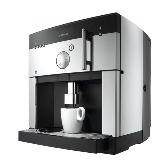
Page 20: Overview Of Machine
Grinding degree setting Milk button / milk foam button Beverage buttons Adjustment lever for all-in-one spout Coffee grounds container Water tank Milk lever (toggles between milk / milk foam) All-in-one spout Drip tray grid Page SMWMF 1000 - 02 - V05... -
Page 21: Control Panel
Milk button / milk foam button Off / c button / timer Readiness display P button / confirmation Display of selected beverage buttons Minus button / care button / aroma button Beverage buttons Plus button / aroma button SMWMF 1000 - 02 - V05 Page... - Page 22 Set the desired grinding degree during the grinding process. • Install the finger protection device. Do not move adjust it by than one complete turn per grind- • Check the grind quality visually (based on the reference ing operation. grind). Page SMWMF 1000 - 02 - V05...
-
Page 23: Grinder
3-1. grinder disks in pairs. Check according to maintenance regulations, section on page 3-1. After the grinder disks are replaced, the counter must be set to zero using the Service Program. SMWMF 1000 - 02 - V05 Page... -
Page 24: Brew Unit
Check according to maintenance regulations, section Soiling (spindle bearings, pistons) on page 3-1. Cleaning Check for proper function and leaks Replace parts: Lower piston incl. O-ring Outlet piston incl. O-ring 4-10 Page SMWMF 1000 - 02 - V05... - Page 25 The scraper ejects the pressed coffee grounds with a pivoting motion. After the grounds are ejected, the brewing cylinder and lower piston return to the home position. 3.035.1 4-11 SMWMF 1000 - 02 - V05 Page...
-
Page 26: Lubrication Schedule For The Brew Unit
After disassembly, cleaning and repair of spare or defective components, the following marked surfaces (bearing and guide surfaces) must be lubricated with a light coat of grease (note the WMF Aktiengesellschaft article numbers). In doing so, note the parts that may not be lubricated and observe the safety regulations and instructions for using food-grade greases. -
Page 27: Vibration Pump
Flow meter Output: Intake side of vibration pump Input: Water tank Hose: 240 mm Hose: 80 mm Nozzle: Ø 1.2 mm Connecting cable: 620 mm Month / year Signal 10. + 5 V 4-13 SMWMF 1000 - 02 - V05 Page... - Page 28 Check for calcification, soiling and mechanical damage. Replace O-ring after opening. Frequently encountered problems: Replace according to maintenance regulations, section Calcification: results in different cup volumes on page 3-1. Complete flow meter 4-14 Page SMWMF 1000 - 02 - V05...
-
Page 29: Air Pump Wmf 1000 Pro
The steam released by the cup warmer valve (d) heats the cup. Maintenance The steam plate can be unlatched (f) and unhooked (g) for cleaning purposes. The steam plate can be rinsed under hot water. Fig. 4-013 Fig. 4-015 Fig. 4-XXX 4-15 SMWMF 1000 - 02 - V05 Page... -
Page 30: Safety Valve
When installing a safety valve, make sure to install it in the correct direction. It is not permitted to disassemble, descale and reas- semble safety valves. 4-16 Page SMWMF 1000 - 02 - V05... -
Page 31: Solenoid Valves
When connecting or replacing solenoid valves, make sure to install them in the correct direction (arrow on the housing). Solenoid valve Valve body - solenoid terminal nut Solenoid Housing Electrical connector tabs Valve body (core guide tube) Plunger 4-17 SMWMF 1000 - 02 - V05 Page... -
Page 32: All-In-One Spout
Replace according to maintenance regulations, section on page 3-1. All-in-one spout Foam chamber Spill-over cup Rotary valve Milk tube Milk nozzle Milk nozzle Air intake pipe Air intake cap 4-18 Page SMWMF 1000 - 02 - V05... -
Page 33: All-In-One Pro Spout
3-1. Fig. 4-019 All-in-one Pro spout Foamer - bottom section Foamer - upper section Milk tube Steam nozzle O-ring Ejector Clip Guide Flange 10. Steam 11. Y-connector plug-in connection 12. Coffee 4-19 SMWMF 1000 - 02 - V05 Page... -
Page 34: Safety Thermostat
Opening contact (approx. 0 Ω!) Flat plug-in connector Check the flat plug-in connectors for oxidation damage. Reset button Thermally conductive paste No other maintenance tasks exist for the safety thermostat. 10. Contact open 4-20 Page SMWMF 1000 - 02 - V05... -
Page 35: Level Probe
Terminal nut GND connection Nipple UCAR seal Steam Insulation (level probe) Level probe tip Water Fig. 4-021 10. Hot water boiler / steam boiler pipe 11. O-ring (cannot be replaced) 12. Clamping ring 4-21 SMWMF 1000 - 02 - V05 Page... -
Page 36: Temperature Sensor
Replace the hot water boiler / steam boiler Fig. 4-023 Cross-section Schematic symbol Fig. 4-024 Temperature sensor NTC resistance wire Sensor tube (stainless steel) Pressure vessel cover Sealing compound (epoxy resin) Connecting cable Connection plug 4-22 Page SMWMF 1000 - 02 - V05... -
Page 37: Fan
Technical data Supply voltage rating: 24 VDC Fig. 4-025 Current: 0.08 A Power: 1.9W Dimensions: 60 x 60 x 15 mm Noise level (max.) 31 dB (A) Direction of rotation: Pictured on housing 4-23 SMWMF 1000 - 02 - V05 Page... -
Page 38: Hot Water Boiler
Safety thermostat Heating time: 10°-->86° approx.:< 2 min. Temperature sensor GND connection Supply inlet (torque 2.2 Nm) Safety valve outlet (torque 2.2 Nm) Hot brewing water line outlet (torque 2.2 Nm) Fig. 4-026 4-24 Page SMWMF 1000 - 02 - V05... -
Page 39: Steam Boiler
Safety thermostat Heat output: 1000 W Temperature sensor Voltage/current: 230 V AC, 4.34 A GND connection Level probe Supply inlet (torque 2.2 Nm) Safety valve/steam line outlet (torque 2.2 Nm) Fig. 4-027 4-25 SMWMF 1000 - 02 - V05 Page... -
Page 40: Threaded Connections/Pipes/Hoses
Transformer secondary voltage: 12 V / 24 V AC The transformer transforms the primary voltage (mains Transformer power: 120 VA voltage) into secondary voltage (consumer voltage). Fig. 4-029 Technical data Primary voltage: 230 VAC ± 10 % 4-26 Page SMWMF 1000 - 02 - V05... -
Page 41: Keyboard Printed Circuit Board (Pcb)
PCB. For instructions specific to the PC board, refer to the function descriptions of the individual compo- nents. Refer to the programming manual for the basic in- structions about the program. 4-27 SMWMF 1000 - 02 - V05 Page... -
Page 42: Esd (Electrostatic Discharge) Protection
In worst-case scenarios, voltages of more than approx. 30 particularly for maintenance work in the field—is applying kV can build up. However, even significantly lower voltages the safety regulations. can destroy components. 4-28 Page SMWMF 1000 - 02 - V05... -
Page 43: Pc Board Layout
Service Manual Function description 4.3.26.2 PC board layout Fig. 4-031 4-29 SMWMF 1000 - 02 - V05 Page... - Page 44 X23.1........+24VDC ......Hot water valve X23.2........0V (switched) ...... Hot water valve X23.3........+24VDC ......Steam valve X23.4........0V (switched) ...... Steam valve X24.1.....Red ....+24VDC ......Fan X24.2.....Black..... 0V (switched) ...... Fan Page SMWMF 1000 - 02 - V05...
- Page 45 X30.3................Reserve valve output X30.4................Reserve valve output X30.5................Reserve valve output X30.6................Reserve valve output X31.1.....Brown ... Relay contact ...... Self-holding X31.2.....Brown ... Relay contact ...... Self-holding 4-31 SMWMF 1000 - 02 - V05 Page...
-
Page 46: Brewing System
Function description Service Manual 4.3.27 Brewing system Cafe Latte Product dispensed: Unit is heated Prerequisite: Unit with all-in-one spout Note: In the following description, some processes are illustrated in simplified form. Fig. 4-028 4-32 Page SMWMF 1000 - 02 - V05... - Page 47 Micro switch on the brew unit signals "Piston Brew unit is in home position. home position reached"; lifting motor is shut off. Close steam valve for all-in-one spout. Steam valve for all-in-one spout closes. 4-33 SMWMF 1000 - 02 - V05 Page...
- Page 48 (timeout). ) The default setting of the steam flow time is 20 seconds (guide value). When the programmed time expires, the steam valve closes independently of the current brewing process. 4-34 Page SMWMF 1000 - 02 - V05...
-
Page 49: Disassembling The Machine
Removing the transformer .............. 5.7 ...5-12 Removing the complete front panel..........5.8 ...5-13 Replacing the panel cover.............. 5.9 ...5-13 Removing the All-in-one spout ............5.10 ..5-13 Removing the All-in-one Pro spout..........5.11 ..5-14 SMWMF 1000 - 02 - V05 Page... -
Page 50: Safety Regulations
However, it is usually necessary to disconnect the machine from these networks before proceeding with further tasks. During installation, ensure that cables are correctly routed. Check that all earthing cables are plugged in properly! Fig. 5-001 Page SMWMF 1000 - 02 - V05... -
Page 51: Removing The Housing
For safety notes, refer to chapter 2 on page 2-1. "Removing the housing"—either partially or completely—is necessary in order to maintain certain components as outlined in chapter 5.3. Disconnect the machine from the mains power supply. SMWMF 1000 - 02 - V05 Page... - Page 52 Special notes Service Manual Size 3 Page SMWMF 1000 - 02 - V05...
- Page 53 Service Manual Special notes SMWMF 1000 - 02 - V05 Page...
-
Page 54: Removing The Hot Water Boiler / Steam Boiler
(h) of the HWB temperature sensor from the PC board. Steam boiler Using bent nose pliers, carefully dis- connect the electrical plug connector (i) of the SB temperature sensor from the PC board. Page SMWMF 1000 - 02 - V05... - Page 55 Insert the cables of the hot water boiler temperature probe (w), the steam boiler temperature probe (x) and the steam boiler level probe (y) into the cut-outs of the "PC board in- sulation" (z). SMWMF 1000 - 02 - V05 Page...
-
Page 56: Removing The Vibration Pump
(c) out of the rubber mount (d) on one side. Pull the vibration pump (e) out of the rubber mount on the other side Rotate the vibration pump 90° clockwise and disconnect the cable connections (a) + (b). Fig. 5-013 Page SMWMF 1000 - 02 - V05... -
Page 57: Removing The Flow Meter
(Fig. 5-017): Lift the flow meter (d) upwards and out of the mount (e). Hold the flow meter lid and rotate the flow meter cup clockwise (bayonet catch) Fig. 5-016 SMWMF 1000 - 02 - V05 Page... - Page 58 If the flow meter lid, Hall sensor or cable strands flow meter are defective, the entire flow meter must be replaced. Refer to section Removing on page 5-11 Fig. 5-020 5-10 Page SMWMF 1000 - 02 - V05...
-
Page 59: Removing The Flow Meter And Cables
Install the new flow meter and insert the cables. Carefully install the middle panel by following the above steps in re- verse order and while ensuring that no cables are pinched in the process. 5-11 SMWMF 1000 - 02 - V05 Page... -
Page 60: Removing The Transformer
Carefully disconnect the electrical plug connectors (b) + (c) of the transformer from the PC board. "Remove" the cables from the machine. Fig. 5-027 5-12 Page SMWMF 1000 - 02 - V05... -
Page 61: Removing The Complete Front Panel
(d) (left and right) and pry the cover up and out. Fig. 5-029 5.10 Removing the All-in-one spout Remove both side walls and the front panel (see p. 5-37 and the following). Fig. 5-030 5-13 SMWMF 1000 - 02 - V05 Page... -
Page 62: Removing The All-In-One Pro Spout
Fig. 5-033 Remove the side covers (see section 5.2, "Removing the housing"). Remove the complete front panel (a) (see section 5.8). The spout (b) can now be removed. 5-14 Page SMWMF 1000 - 02 - V05... -
Page 63: Special Notes
Service Manual Special notes SPECIAL NOTES Drainage ............................6.1 SMWMF 1000 - 02 - V04 Page... - Page 64 The machine indicates that it is in standby. You can now exit the Service Program and unplug the cable connec- tion to the computer. Unplug the power cord from the socket. Assemble the machine. Fig. 6-004 Fig. 6-005 Page SMWMF 1000 - 02 - V05...
Need help?
Do you have a question about the 1000 and is the answer not in the manual?
Questions and answers