
Related Manuals for Miller Electric Dimension NT 450, NT 500


Summary of Contents for Miller Electric Dimension NT 450, NT 500
- Page 1 Dimension NT 450 Dimension NT 500 Visit our website at www.MillerWelds.com OM-2252 2008−01 Processes Multiprocess Welding Description Arc Welding Power Source File: Multiprocess Welding 218 084R...
- Page 2 ISO 9001:2000 Quality System Standard. particular model are also provided. Miller Electric manufactures a full line of welders and welding related equipment. For information on other quality Miller products, contact your local Miller distributor to receive the latest full line catalog or individual specification sheets.
-
Page 3: Table Of Contents
TABLE OF CONTENTS SECTION 1 − SAFETY PRECAUTIONS - READ BEFORE USING 1-1. Symbol Usage ............... . 1-2. - Page 4 Notes...
-
Page 5: Section 1 − Safety Precautions - Read Before Using
DC constant voltage (wire) welder, 2) a DC manual (stick) welder, or 3) an AC welder with reduced open-circuit volt- age. In most situations, use of a DC, constant voltage wire welder is recommended. And, do not work alone! D Disconnect input power or stop engine before installing or servicing this equipment. - Page 6 OM-2252 Page 2 D Do not use welder to thaw frozen pipes. D Remove stick electrode from holder or cut off welding wire at contact tip when not in use.
-
Page 7: Additional Symbols For Installation, Operation, And Maintenance
1-3. Additional Symbols For Installation, Operation, And Maintenance FIRE OR EXPLOSION hazard. D Do not install or place unit on, over, or near combustible surfaces. D Do not install unit near flammables. D Do not overload building wiring − be sure power supply system is properly sized, rated, and protected to handle this unit. -
Page 8: California Proposition 65 Warnings
1-4. California Proposition 65 Warnings Welding or cutting equipment produces fumes or gases which contain chemicals known to the State of California to cause birth defects and, in some cases, cancer. (California Health & Safety Code Section 25249.5 et seq.) Battery posts, terminals and related accessories contain lead and lead compounds, chemicals known to the State of California to cause cancer and birth defects or other... -
Page 9: Section 2 − Consignes De Sécurité − Lire Avant Utilisation
SECTION 2 − CONSIGNES DE SÉCURITÉ − LIRE AVANT UTILISATION Se protéger et protéger les autres contre le risque de blessure — lire et respecter ces consignes. 2-1. Symboles utilisés DANGER! − Indique une situation dangereuse qui si on l’évite pas peut donner la mort ou des blessures graves. Les dangers possibles sont montrés par les symboles joints ou sont expliqués dans le texte. - Page 10 Il reste une TENSION DC NON NÉGLIGEABLE dans les sources de soudage onduleur quand on a coupé l’alimentation. D Arrêter les convertisseurs, débrancher le courant électrique et décharger les condensateurs d’alimentation selon les instructions indiquées dans la partie Entretien avant de toucher les pièces. DES PIÈCES CHAUDES peuvent provoquer des brûlures graves.
-
Page 11: Dangers Supplémentaires En Relation Avec L'installation, Le Fonctionnement Et La Maintenance
ACCUMULATIONS risquent de provoquer des blessures ou même la mort. D Fermer l’alimentation du gaz protecteur en cas de non-utilisation. D Veiller toujours à bien aérer les espaces confi- nés ou se servir d’un respirateur d’adduction d’air homologué. LES CHAMPS MAGNETIQUES peuv- ent affecter des implants médicaux. -
Page 12: Proposition Californienne 65 Avertissements
LES FILS DE SOUDAGE peuvent provoquer des blessures. D Ne pas appuyer sur la gâchette avant d’en avoir reçu l’instruction. D Ne pas diriger le pistolet vers soi, d’autres per- sonnes ou toute pièce mécanique en enga- geant le fil de soudage. DES ORGANES MOBILES peuvent provoquer des blessures. -
Page 13: Principales Normes De Sécurité
2-5. Principales normes de sécurité Safety in Welding, Cutting, and Allied Processes, ANSI Standard Z49.1, de Global Engineering Documents (téléphone : 1-877-413-5184, site Internet : www.global.ihs.com). Recommended Safe Practices for the Preparation for Welding and Cut- ting of Containers and Piping, American Welding Society Standard AWS F4.1 de Global Engineering Documents (téléphone : 1-877-413-5184, site Internet : www.global.ihs.com). - Page 14 OM-2252 Page 10...
-
Page 15: Section 3 − Definitions
SECTION 3 − DEFINITIONS 3-1. General Precautionary Label Warning! Watch Out! There are possible hazards as shown by the symbols. Electric shock from welding electrode or wiring can kill. 1.1 Wear dry insulating gloves. Do not touch electrode with bare hand. Do not wear wet or damaged gloves. -
Page 16: Input Connection Label
3-2. Input Connection Label 1/96 Í Í Í Í 3-3. Electric Shock And Airflow Label 3-4. Nameplate Safety Symbols OM-2252 Page 12 Í Í Í Í Í Í Í Í Í Í Í Í S-179 290 Warning! Watch Out! There are possible hazards as shown by the symbols. -
Page 17: Section 4 − Installation
SECTION 4 − INSTALLATION 4-1. Specifications Rated Amperage/ Welding Welding Model Model Voltage Range Voltage Range Output 5 − 500A In CC Mode 450 A @ 38 450 Amp 450 Amp Volts DC, 100% Volts DC 100% Duty Cycle 10 − 38V In CV Mode *While idling 4-2. -
Page 18: Volt-Ampere Curves
4-3. Volt-Ampere Curves A. CC Mode B. CV Mode OM-2252 Page 14 DC Current DC Current Volt-ampere curves show mini- mum and maximum voltage and amperage output capabilities of unit. Curves of other settings fall be- tween curves shown. va_curve1 − 4/95 − 212 111-A / 212 112-A... -
Page 19: Selecting A Location
4-4. Selecting A Location Movement Location 18 in (460 mm) 18 in (460 mm) Lifting Eye Lifting Forks Use lifting eye or lifting forks to move unit. If using lifting forks, extend forks beyond opposite side of unit. Plate Label Rating Label CE Models −... -
Page 20: Dimensions And Weights
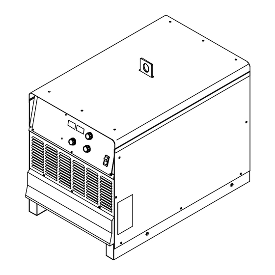
4-5. Dimensions And Weights OM-2252 Page 16 Dimensions 30 in (762 mm) including lift eye 23 in (585 mm) 38 in (966 mm) including strain relief 35 in (889 mm) 1-1/4 in (32 mm) 21-1/8 in (537 mm) 1-1/8 in (29 mm) 7/16 in (11 mm) Dia Weight 376 lb (171 kg) -
Page 21: Tipping
4-6. Tipping 4-7. 115 VAC Receptacle And Circuit Breakers Do not move or operate unit where it could tip. Turn power before connecting to receptacle. 115 V 15 A AC Receptacle RC15 Power is shared between RC15 and Remote 14 receptacle RC14 (see Section 4-11). -
Page 22: Weld Output Terminals And Selecting Cable Sizes
4-8. Weld Output Terminals And Selecting Cable Sizes Turn Off power before Turn Off power before connecting to weld output terminals. Welding Amperes Negative Positive Terminal Terminal *Weld cable size (AWG) is based on either a 4 volts or less drop or a current density of at least 300 circular mils per ampere. Contact your distributor for the mm equivalent weld cable sizes. -
Page 23: Remote 14 Receptacle Information
4-10. Remote 14 Receptacle Information 24 VOLTS AC 115 VOLTS AC REMOTE OUTPUT OUTPUT CONTROL AMPERAGE AMPERAGE VOLTAGE *The remaining sockets are not used. 4-11. Connecting Remote Control Socket* 24 volts ac. Protected by circuit breaker CB2. Contact closure to A completes 24 volts ac contactor control circuit. 115 volts ac. -
Page 24: Electrical Service Guide
4-12. Electrical Service Guide Failure to follow these electrical service guide recommendations could create an electric shock or fire hazard. These recommenda- tions are for a dedicated branch circuit sized for the rated output and duty cycle of the welding power source. 50/60 Hertz Models Input Voltage Input Amperes At Rated Output... -
Page 25: Connecting Input Power
4-14. Connecting Input Power L1 (U) L2 (V) L3 (W) Tools Needed: 1/2 in 3/8 in = GND/PE Earth Ground IMPORTANT Input Contactor GND/ PE Earth Ground Installation must meet all National and Local Codes − have only quali- fied persons make this installation. Disconnect and lockout/tagout in- put power before connecting input conductors from unit. -
Page 26: Section 5 − Operation
SECTION 5 − OPERATION 5-1. Controls Power Switch This unit is equipped with a fan motor that is thermostatically controlled and only runs when cooling is needed. Voltmeter (see Section 5-2) Ammeter (see Section 5-2) Mode Switch Use Mode switch to determine both process and output On/Off control. -
Page 27: Meter Functions For Cc/Cv Models
5-2. Meter Functions For CC/CV Models The meters display the actual weld output values for approximately three seconds after the arc is broken. Mode Scratch Start TIG Lift-Arc TIG (GTAW) Air Carbon Arc TIG (GTAW) MIG (GMAW) Stick (SMAW) Voltage-Sensing Wirefeeder 5-3. -
Page 28: Section 6 − Maintenance & Troubleshooting
SECTION 6 − MAINTENANCE & TROUBLESHOOTING 6-1. Routine Maintenance n = Check Z = Change * To be done by Factory Authorized Service Agent Every Months nl Labels Every Months n lCables And Cords Every Months ~:Durning heavy service, clean monthly. 6-2. -
Page 29: Voltmeter/Ammeter Help Displays
30 sec- onds. The display flashes a HELP 6 message during idle, but the welder continues to operate normally. Once the primary voltage returns to less than 10% below the linked primary voltage setting the flashing error ceases. -
Page 30: Troubleshooting
6-4. Troubleshooting Trouble No weld output; unit completely inop- Place line disconnect device in On position (see Section 4-14). erative; pilot light PL1 off. Check for open line fuse(s), and replace if open (see Section 4-14). Check for proper input power connections (see Section 4-14). Check for proper jumper link position (see Section 4-13). - Page 31 Notes Work like a Pro! Pros weld and cut safely. Read the safety rules at the beginning of this manual. OM-2252 Page 27...
-
Page 32: Section 7 − Electrical Diagram
SECTION 7 − ELECTRICAL DIAGRAM Figure 7-1. Circuit Diagram For Dimension NT OM-2252 Page 28... - Page 33 218 081-F OM-2252 Page 29...
-
Page 34: Section 8 − Parts List
SECTION 8 − PARTS LIST Item Dia. Part Mkgs....Fig 8-2 PANEL, Front w/Components ... . . 217 136 LABEL,WARNING ELECTRIC SHOCK . - Page 35 Item Dia. Part Mkgs..159 244 PRIMARY BOX (Includes), ....601 835 . . . NUT, 10-32 BRASS ....038 887 .
- Page 36 Hardware is common and not available unless listed. OM-2252 Page 32 Figure 8-2. Panel, Front With Components Hardware is common and not available unless listed. 803 897-G...
- Page 37 Item Dia. Part Mkgs....204 143 PANEL, FRONT ..181 245 TERMINAL, PWR OUTPUT RED . . . C4, 5 230 729 CAPACITOR, CER DISC .1 UF 500 VDC W/TERMS .
- Page 38 Hardware is common and not available unless listed. 803 937-C Figure 8-3. IGBT/Capacitor Assembly OM-2252 Page 34...
- Page 39 Item Dia. Part Mkgs. 221 298 ... . . 221 301 BUS PLATE, IGBT TO CAPACITOR NEGATIVE ... . . 221 304 STAND−OFF, CONDUCTIVE BUS .
- Page 40 Hardware is common and not available unless listed. Item Dia. Part Mkgs....173 283 ....180 165 .
- Page 41 Notes...
- Page 42 Notes Work like a Pro! Pros weld and cut safely. Read the safety rules at the beginning of this manual.
- Page 43 Warranty Questions? LIMITED WARRANTY − Subject to the terms and conditions Call below, Miller Electric Mfg. Co., Appleton, Wisconsin, warrants to 1-800-4-A-MILLER its original retail purchaser that new Miller equipment sold after the effective date of this limited warranty is free of defects in for your local material and workmanship at the time it is shipped by Miller.
-
Page 44: Owner's Record
File a claim for loss or damage during shipment. For assistance in filing or settling claims, contact your distributor and/or equipment manufacturer’s Transportation Department. 2007 Miller Electric Mfg. Co. 2007−01 Miller Electric Mfg. Co. An Illinois Tool Works Company 1635 West Spencer Street Appleton, WI 54914 USA International Headquarters−USA...
Need help?
Do you have a question about the Dimension NT 450, NT 500 and is the answer not in the manual?
Questions and answers