Table of Contents
Troubleshooting

Related Manuals for Miller Electric Renegade 180


Summary of Contents for Miller Electric Renegade 180
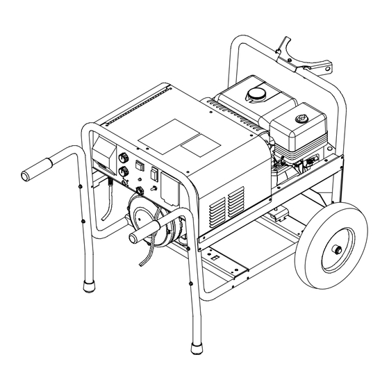
- Page 1 Visit our website at www.MillerWelds.com Renegade 180 OM-228 042B 2007−09 Processes Processes MIG (GMAW) Welding Flux Cored (FCAW) Welding Description Engine Driven Welding Power Source/ Wire Feeder/Generator File: Engine Drive...
- Page 2 ISO 9001:2000 Quality System Standard. particular model are also provided. Miller Electric manufactures a full line of welders and welding related equipment. For information on other quality Miller products, contact your local Miller distributor to receive the latest full line catalog or individual specification sheets.
-
Page 3: Table Of Contents
TABLE OF CONTENTS SECTION 1 − SAFETY PRECAUTIONS − READ BEFORE USING 1-1. Symbol Usage ............... 1-2. - Page 4 TABLE OF CONTENTS SECTION 8 − MAINTENANCE ............. . . 8-1.
-
Page 5: Section 1 − Safety Precautions − Read Before Using
SECTION 1 − SAFETY PRECAUTIONS − READ BEFORE USING Protect yourself and others from injury — read and follow these precautions. 1-1. Symbol Usage DANGER! − Indicates a hazardous situation which, if not avoided, will result in death or serious injury. The possible hazards are shown in the adjoining symbols or explained in the text. -
Page 6: Noise Can Damage Hearing
FUMES AND GASES can be hazardous. Welding produces fumes and gases. Breathing these fumes and gases can be hazardous to your health. D Keep your head out of the fumes. Do not breathe the fumes. D If inside, ventilate the area and/or use local forced ventilation at the arc to remove welding fumes and gases. -
Page 7: Engine Hazards
1-3. Engine Hazards BATTERY EXPLOSION can BLIND. D Always wear a face shield, rubber gloves, and protective clothing when working on a battery. D Stop engine before disconnecting or connect- ing battery cables or servicing battery. D Do not allow tools to cause sparks when working on a battery. D Do not use welder to charge batteries or jump start vehicles. -
Page 8: Additional Symbols For Installation, Operation, And Maintenance
HOT METAL from air arc cutting and gouging can cause fire or explosion. D Do not cut or gouge near flammables. D Watch for fire; keep extinguisher nearby. HOT PARTS can cause burns and injury. D Do not touch hot compressor or air system parts. -
Page 9: California Proposition 65 Warnings
H.F. RADIATION can cause interference. D High-frequency (H.F.) can interfere with radio navigation, safety services, computers, and communications equipment. D Have only qualified persons familiar with electronic equipment perform this installation. D The user is responsible for having a qualified electrician promptly correct any interference problem resulting from the installation. -
Page 10: Section 2 − Consignes De Sécurité − Lire Avant Utilisation
SECTION 2 CONSIGNES DE SÉCURITÉ − LIRE AVANT − Se protéger, ainsi que toute autre personne travaillant sur les lieux, contre les étincelles et le métal chaud. 2-1. Signification des symboles DANGER! − Indique une situation dangereuse qui si on l’évite pas peut donner la mort ou des blessures graves. - Page 11 Une tension DC importante subsiste à l’intérieur des onduleurs après avoir coupé l’alimentation. D Couper l’alimentation du poste et décharger les condensateurs d’entrée comme indiqué dans la Section Maintenance avant de toucher des composants. DES PIÈCES CHAUDES peuvent provoquer des brûlures graves. D Ne pas toucher à...
-
Page 12: Dangers Existant En Relation Avec Le Moteur
D Suivre les recommandations dans OSHA 1910.252(a)(2)(iv) et NFPA 51B pour les travaux à chaud et avoir de la surveillance et un extincteur à proximité. LE BRUIT peut affecter l’ouïe. Le bruit des processus et des équipements peut affec l’ouïe. D Porter des protections approuvés pour les ore les si le niveau sonore est trop élevé. -
Page 13: Dangers Liés À L'air Comprimé
D Dévisser le bouchon légèrement et laisser la vapeur s’échapper avant d’enlever le bouchon. L’utilisation d’un groupe autonome à l’intérieur PEUT VOUS TUER EN QUELQUES MINUTES. D Les fumées d’un groupe autonome contient du monoxyde de carbone. C’est un poison invisi- ble et inodore. - Page 14 LE SURCHAUFFEMENT peut endom- mager le moteur électrique. D Arrêter ou déconnecter l’équipement avant de démarrer ou d’arrêter le moteur. D Ne pas laisser tourner le moteur trop lentement sous risque d’en- dommager le moteur électrique à cause d’une tension et d’une fré- quence trop faibles.
-
Page 15: Proposition Californienne 65 Avertissements
2-6. Proposition californienne 65 Avertissements Les équipements de soudage et de coupage produisent des fumées et des gaz qui contiennent des produits chimiques dont l’État de Californie reconnaît qu’ils provoquent des mal- formations congénitales et, dans certains cas, des cancers. (Code de santé... -
Page 16: Section 3 − Definitions
SECTION 3 − DEFINITIONS 3-1. Symbol Definitions Engine Choke Engine Oil Positive Hours Wire Speed Spool Gun SECTION 4 − SPECIFICATIONS 4-1. Description This unit is an engine driven welding power source/wire feeder with auxiliary power capability. The welding power source/wire feeder can also use utility power to provide weld output (no auxiliary power available in this mode). -
Page 17: Gun Specifications
4-3. Gun Specifications Air-Cooled Welding Guns For GMAW And FCAW Welding M-15 Feeds .023 To .045 in. (0.6 To 1.1 mm) Hard Or Flux Cored Wires .045 in. (1.1 mm) wire requires liner change to MILLER Part No. 194012 in addition to contact tip change Duty Cycle Rating: 100%: 150 A With CO 60%: 200 A With CO... -
Page 18: Fuel Consumption
4-6. Fuel Consumption 1.00 0.80 0.60 0.40 0.20 0.00 Auxiliary Power Kw At 100% Duty Cycle 4-7. Power Source Duty Cycle 25 30 % Duty Cycle 30% duty cycle at 135 amps, 60 Hz 20% duty cycle at 130 amps, 50 Hz 3 Minutes Welding Overheating OM-228 042 Page 14... -
Page 19: Gun Duty Cycle And Overheating
4-8. Gun Duty Cycle And Overheating 100%dutycycle 6 Minutes Welding Continuous Welding Overheating 4-9. Generator Power Curve 240 Volt 120 Volt Complete Parts List available at www. MillerWelds.com 60%dutycycle 4 Minutes Resting Reduce Duty Cycle Minutes AC Amperes See Section 4-3. Specifications for amperage rating and duty cycle. -
Page 20: Section 5 − Installation
SECTION 5 − INSTALLATION 5-1. Installing Welding Generator Movement Shown with standard running gear and optional cylinder rack. Location Always securely fasten welding generator onto transport vehicle or trailer and comply with all DOT and other applicable codes. GND/PE OM-228 042 Page 16 Complete Parts List available at www. -
Page 21: Grounding Generator When Supplying Building Systems
5-2. Grounding Generator When Supplying Building Systems Notes WELD POSITION: FLAT BUTT WELD JOINT TYPES GROOVE FILLET T−JOINT Ref. AWS/ANSI D1.1 Complete Parts List available at www. MillerWelds.com GND/PE HORIZONTAL BUTT T−JOINT Ground generator to sys- tem earth ground if supply- ing power to a premises (home, shop, farm) wiring system. -
Page 22: Engine Prestart Checks
5-3. Engine Prestart Checks 1/2 in (13 mm) Full Gasoline 5-4. Connecting The Battery (Electric Start Models Only) OM-228 042 Page 18 Complete Parts List available at www. MillerWelds.com Full Connect negative (−) cable last. − Check all fluids daily. Engine must be cold and on a level surface. -
Page 23: Installing Welding Gun
5-5. Installing Welding Gun 5-6. Work Cable Routing Inside Unit Complete Parts List available at www. MillerWelds.com Drive Assembly Gun Securing Knob Gun End Loosen knob. Insert gun end through opening until it bottoms against drive assembly. Tighten knob. Gun Trigger Plug Insert into receptacle, and tighten threaded collar. -
Page 24: Weld Process/Polarity Table
5-7. Weld Process/Polarity Table Weld Process Weld Process GMAW − Solid wire with shield- DCEP − Reverse polarity ing gas FCAW − Self-shielding wire − DCEN − Straight Polarity no shielding gas 5-8. Changing Weld Polarity OM-228 042 Page 20 Complete Parts List available at www. -
Page 25: Connecting Single−Phase, 230 Volt Ac Utility Input Power
5-9. Connecting Single−Phase, 230 Volt AC Utility Input Power =GND/PE Earth Ground Tools Needed: Complete Parts List available at www. MillerWelds.com 230 VAC, 1 Shown with optional cylinder rack This unit can provide weld out- put using the engine to power the welding power source/wire feeder OR single−phase 230 volt ac utility power can be... -
Page 26: Electrical Service Guide
5-10. Electrical Service Guide Input Voltage Input Amperes At Rated Output Max Recommended Standard Fuse Rating In Amperes Min Input Conductor Size In AWG Max Recommended Input Conductor Length In Feet (Meters) Min Grounding Conductor Size In AWG Reference: 2005 National Electrical Code (NEC) (including article 630) 1 Choose a circuit breaker with time-current curves comparable to a Time Delay Fuse. - Page 27 Complete Parts List available at www. MillerWelds.com Notes Ref. AWS/ANSI D1.1 WELD JOINT TYPES GROOVE FILLET WELD POSITION: FLAT BUTT T−JOINT HORIZONTAL BUTT T−JOINT VERTICAL BUTT T−JOINT OVERHEAD BUTT T−JOINT Ref. 804 248-A OM-228 042 Page 23...
-
Page 28: Threading The Welding Gun
Complete Parts List available at www. MillerWelds.com 5-12. Threading The Welding Gun Tools Needed: 6 in (150 mm) .030/.035 Groove .024 Groove Stamped .024 Stamped .030/.035 Tighten Pressure Indicator Scale 804 755-B / Ref. 229 573-A OM-228 042 Page 24... - Page 29 Complete Parts List available at www. MillerWelds.com Wire Spool Welding Wire Inlet Wire Guide Pressure Adjustment Knob Drive Roll Gun Conduit Cable Lay gun cable out straight. Open pressure assembly. Pull about 6 in. (150 mm) of wire off spool. Hold tightly to keep it from unraveling.
-
Page 30: Section 6 − Operating The Welding Generator
Complete Parts List available at www. MillerWelds.com SECTION 6 − OPERATING THE WELDING GENERATOR 6-1. Controls (See Section 6-2) Electric Start Models Recoil Start Models 229 573 / 804 971-B OM-228 042 Page 26... -
Page 31: Description Of Controls (See Section 6-1)
6-2. Description Of Controls (See Section 6-1) Engine Switch Use switch to control ignition circuit. For Recoil Start: Turn switch to On position when starting engine. Turn switch to Off posi- tion to stop engine. Engine cannot be started with switch in the Off position. For Electric Start: Turn switch to Start position when starting engine. -
Page 32: Weld Parameter Chart
Complete Parts List available at www. MillerWelds.com 6-3. Weld Parameter Chart Ref. 230 748C OM-228 042 Page 28... -
Page 33: Stainless Steel And 100% Co2 Weld Parameters
6-4. Stainless Steel And 100% CO2 Weld Parameters Select Wire Type, Polarity, and Shielding Select Wire Type, Polarity, and Shielding Solid ER70S−6 (DCEP) 100% CO2 Shielding Gas 100% CO2 Shielding Gas Stainless Steel (DCEP) Tri−Mix Shielding Gas Tri Mix Shielding Gas 90% HE/7.5% Ar/ 2.5% CO2 90% HE/7.5% Ar/ 2.5% CO2 Aluminum 4043 (DCEP) -
Page 34: Section 7 − Operating Auxiliary Equipment
SECTION 7 − OPERATING AUXILIARY EQUIPMENT 7-1. Generator Power Panel Receptacles If unit does not have GFCI recep- tacles, use GFCI-protected exten- sion cord. Generator power decreases as weld current increases. 240 V AC Receptacle RC1 RC1 supplies 60 Hz single-phase power at weld/power speed. -
Page 35: Section 8 − Maintenance
SECTION 8 − MAINTENANCE 8-1. Power Source Routine Maintenance Follow the storage procedure in the engine owner’s manual if the unit will not be used for an extended period. n = Check Z = Change * To be done by Factory Authorized Service Agent Every Hours n Fuel Level... -
Page 36: Gun Routine Maintenance
8-2. Gun Routine Maintenance n = Check Z = Change Every Spool Of Wire ~ Gun Casing ~ Nozzle, n Contact Tip Every 3 Months l Cracked Parts l Cracked Parts 8-3. Welding Power Source Overload Protection 8-4. Drive Motor Protection And Tip Saver/Short Circuit Protection A. -
Page 37: Changing Drive Roll Or Wire Inlet Guide
8-5. Changing Drive Roll Or Wire Inlet Guide .030/.035 Groove .024 Groove Stamped .024 Stamped .030/.035 8-6. Replacing Gun Contact Tip Tools Needed: Complete Parts List available at www. MillerWelds.com Remove guide by pressing on barbed area or cutting off one end near housing and pulling it out of hole. -
Page 38: Maintaining Gun
8-7. Maintaining Gun Tools Needed: 3/8 in OM-228 042 Page 34 Complete Parts List available at www. MillerWelds.com 3/4 in (20 mm) Turn off welding power source/wire feeder. Nozzle Contact Tip Adapter Head Tube Cut off wire and disconnect gun from feeder Remove nozzle contact tip and adapter from head tube. -
Page 39: Replacing Switch And/Or Head Tube
8-8. Replacing Switch And/Or Head Tube Tools Needed: 19 mm Complete Parts List available at www. MillerWelds.com Turn off welding power source/wire feeder and dis- connect gun. Handle Locking Nut Switch Housing Handle Vise Head Tube Jam Nut Remove handle locking nut. Remove switch housing. -
Page 40: Servicing Air Cleaner
8-9. Servicing Air Cleaner Standard Model Shown OM-228 042 Page 36 Complete Parts List available at www. MillerWelds.com Stop engine. NOTICE − Do not run engine with- out air cleaner or with dirty element. Precleaner Paper Element Do not wash paper element or clean with compressed air. -
Page 41: Adjusting Engine Speed
8-10. Adjusting Engine Speed Tools Needed: Complete Parts List available at www. MillerWelds.com After tuning engine, check engine speed. See table for proper no load speed. If necessary, adjust speed as follows: Start engine and run until warm. ± 3750 30 rpm (62 Hz) Adjustment Screw To increase speed, turn screw in... -
Page 42: Section 9 − Troubleshooting
SECTION 9 − TROUBLESHOOTING 9-1. Troubleshooting A. Welding Trouble No weld output or generator power out- Be sure all equipment is disconnected from receptacles when starting unit. put at ac receptacles. Place switch in Wall position or start engine and place switch in Generator position. AC receptacles provide auxiliary power only while engine is running. -
Page 43: Wire Feeder
Trouble Low output at generator power ac Check engine speed, and adjust if necessary (see Section 8-10 ). Open circuit voltage is reduced as receptacles. engine speed drops. Erratic output at generator power ac Check fuel level. receptacles. receptacles Have Factory Authorized Service Agent check connections at terminal block 1T. Check receptacle supplementary protector, wiring, and connections. -
Page 44: Section 10 − Parts List
Trouble Engine will not start. Check fuel level (see Section 5-3). Move choke control to correct position (see Section 6-1). Open fuel valve (see Section 5-3). Close fuel valve before moving unit or carburetor may flood and make starting difficult. Be sure engine switch is On. -
Page 45: Section 11 − Electrical Diagrams
SECTION 11 − ELECTRICAL DIAGRAMS Figure 11-1. Circuit Diagram For Welding Generator OM-217 454 Page 41... -
Page 46: Section 12 − Mig Welding (Gmaw) Guidelines
SECTION 12 − MIG WELDING (GMAW) GUIDELINES 12-1. Typical MIG Process Connections Regulator/ Flowmeter Gas Hose Shielding Gas OM-228 042 Page 42 Wire Feeder/ Power Source Weld current can damage electronic parts in vehicles. Disconnect both battery cables before welding on a vehicle. -
Page 47: Typical Mig Process Control Settings
12-2. Typical MIG Process Control Settings These settings are guidelines only. Material and wire type, joint design, fitup, position, shielding gas, etc. affect settings. Test welds to be sure they comply to specifications. These settings are guidelines only. Material and wire type, joint design, fitup, position, 1/8 or shielding gas, etc. -
Page 48: Holding And Positioning Welding Gun
12-3. Holding And Positioning Welding Gun Welding wire is energized when gun trigger is pressed. Before lowering helmet and pressing trigger, be sure wire is no more than 1/2 in (13 mm) past end of nozzle, and tip of wire is positioned correctly on seam. °... -
Page 49: Conditions That Affect Weld Bead Shape
12-4. Conditions That Affect Weld Bead Shape Weld bead shape depends on gun angle, direction of travel, electrode extension (stickout), travel speed, thickness of base metal, wire feed speed (weld current), and voltage. ° ° Weld bead shape depends on gun angle, direction of travel, electrode extension (stickout), travel speed, thickness of base... -
Page 50: Poor Weld Bead Characteristics
12-5. Gun Movement During Welding Normally, a single stringer bead is satisfactory for most narrow groove weld joints; however, for wide groove weld joints or bridging across gaps, a weave bead or multiple stringer beads works better. 12-6. Poor Weld Bead Characteristics 12-7. -
Page 51: Troubleshooting − Excessive Spatter
12-8. Troubleshooting − Excessive Spatter Possible Causes Wire feed speed too high. Voltage too high. Electrode extension (stickout) too long. Workpiece dirty. Insufficient shielding gas at welding arc. Dirty welding wire. Wrong polarity. 12-9. Troubleshooting − Porosity Possible Causes Insufficient shielding gas at welding arc. Wrong gas. -
Page 52: Troubleshooting − Excessive Penetration
12-10. Troubleshooting − Excessive Penetration Excessive Penetration Good Penetration Possible Causes Excessive heat input. Wrong polarity. 12-11. Troubleshooting − Lack Of Penetration Lack of Penetration Good Penetration Possible Causes Improper joint preparation. Improper weld technique. Insufficient heat input. Wrong polarity. 12-12. -
Page 53: Troubleshooting − Burn-Through
12-13. Troubleshooting − Burn-Through Possible Causes Excessive heat input. Wrong polarity. 12-14. Troubleshooting − Waviness Of Bead Possible Causes Welding wire extends too far out of nozzle. Unsteady hand. 12-15. Troubleshooting − Distortion Base metal moves in the direction of the weld bead. -
Page 54: Common Mig Shielding Gases
12-16. Common MIG Shielding Gases This is a general chart for common gases and where they are used. Many different combinations (mixtures) of shielding gases have been developed over the years. The most commonly used shielding gases are listed in the following table. -
Page 55: Section 13 − Generator Power Guidelines
SECTION 13 − GENERATOR POWER GUIDELINES The views in this section are intended to be representative of all engine-driven welding generators. Your unit may differ from those shown. 13-1. Selecting Equipment 13-2. Grounding Generator To Truck Or Trailer Frame GND/PE Generator Power Receptacles −... -
Page 56: Grounding When Supplying Building Systems
13-3. Grounding When Supplying Building Systems 13-4. How Much Power Does Equipment Require? OM-228 042 Page 52 GND/PE VOLTS 115 AMPS Equipment Grounding Terminal Grounding Cable Use #10 AWG or larger insulated copper wire. Ground Device Use ground device as stated in electrical codes. - Page 57 13-5. Approximate Power Requirements For Industrial Motors Industrial Motors Split Phase Capacitor Start-Induction Run Capacitor Start-Capacitor Run Fan Duty 13-6. Approximate Power Requirements For Farm/Home Equipment Farm/Home Equipment Stock Tank De-Icer Grain Cleaner Portable Conveyor Grain Elevator Milk Cooler Milker (Vacuum Pump) FARM DUTY MOTORS Std.
- Page 58 13-7. Approximate Power Requirements For Contractor Equipment Contractor Hand Drill Circular Saw Table Saw Band Saw Bench Grinder Air Compressor Electric Chain Saw Electric Trimmer Electric Cultivator Elec. Hedge Trimmer Flood Lights Submersible Pump Centrifugal Pump Floor Polisher High Pressure Washer 55 gal Drum Mixer Wet &...
-
Page 59: Power Required To Start Motor
13-8. Power Required To Start Motor Motor Start Code KVA/HP 13-9. How Much Power Can Generator Supply? Single-Phase Induction Motor Starting Requirements 10.0 AC MOTOR VOLTS AMPS CODE PHASE 11.2 12.5 Motor Start Code Running Amperage Motor HP Motor Voltage To find starting amperage: Step 1: Find code and use table to find kVA/HP. - Page 60 13-10. Typical Connections To Supply Standby Power Utility Electrical Transfer Switch Service Essential Loads OM-228 042 Page 56 Fused Welding Disconnect Generator Switch Output (If Required) Have only qualified persons perform these connections according to all applicable codes and safety practices. Properly install and ground this equipment according to its Owner’s Manual and na-...
-
Page 61: Selecting Extension Cord (Use Shortest Cord Possible)
13-11. Selecting Extension Cord (Use Shortest Cord Possible) Cord Lengths for 120 Volt Loads If unit does not have GFCI receptacles, use GFCI-protected extension cord. Current Load (Watts) (Amperes) 1200 1800 2400 3000 3600 4200 4800 5400 6000 *Conductor size is based on maximum 2% voltage drop Cord Lengths for 240 Volt Loads If unit does not have GFCI receptacles, use GFCI-protected extension cord. - Page 62 Notes SOCKET/WRENCH SELECTION TABLE (U.S. STANDARD) Specifications Socket or Wrench Size Bolt Decimal Bolt Diameter Equivalent 1/4 in .250 in 3/8 in 5/16 in .3125 in 1/2 in 3/8 in .375 in 9/16 in 7/16 in .4375 in 5/8 in 1/2 in .500 in 3/4 in...
- Page 63 Warranty Questions? LIMITED WARRANTY − Subject to the terms and conditions Call below, Miller Electric Mfg. Co., Appleton, Wisconsin, warrants to 1-800-4-A-MILLER its original retail purchaser that new Miller equipment sold after the effective date of this limited warranty is free of defects in for your local material and workmanship at the time it is shipped by Miller.
-
Page 64: Owner's Record
For assistance in filing or settling claims, contact your distributor and/or equipment manufacturer’s Transportation Department. © 2007 Miller Electric Mfg. Co. 2007−01 Miller Electric Mfg. Co. An Illinois Tool Works Company 1635 West Spencer Street Appleton, WI 54914 USA International Headquarters−USA...
Need help?
Do you have a question about the Renegade 180 and is the answer not in the manual?
Questions and answers