
Related Manuals for Miller Electric Spectrum 125C


Summary of Contents for Miller Electric Spectrum 125C
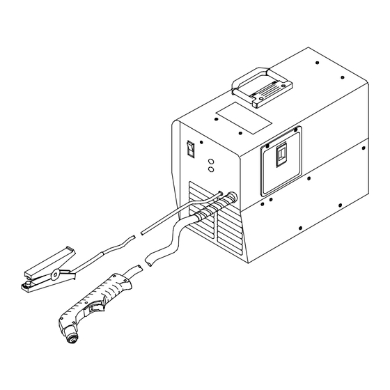
- Page 1 Visit our website at www.MillerWelds.com Spectrum 125C And ICE-12C Torch OM-2248 213 990E 2007−02 Processes Air Plasma Cutting and Gouging Description Air Plasma Cutter File: Plasma Cutters...
- Page 2 ISO 9001:2000 Quality System Standard. particular model are also provided. Miller Electric manufactures a full line of welders and welding related equipment. For information on other quality Miller products, contact your local Miller distributor to receive the latest full line catalog or individual specification sheets.
-
Page 3: Table Of Contents
TABLE OF CONTENTS SECTION 1 − SAFETY PRECAUTIONS - READ BEFORE USING 1-1. Symbol Usage ............... . 1-2. -
Page 5: Section 1 − Safety Precautions - Read Before Using
SECTION 1 − SAFETY PRECAUTIONS - READ BEFORE USING Y Warning: Protect yourself and others from injury — read and follow these precautions. 1-1. Symbol Usage Means Warning! Watch Out! There are possible hazards with this procedure! The possible hazards are shown in the adjoining symbols. - Page 6 EXPLODING PARTS can injure. D On inverter power sources, failed parts can ex- plode or cause other parts to explode when power is applied. Always wear a face shield and long sleeves when servicing inverters. FLYING SPARKS can cause injury. Sparks and hot metal blow out from the cutting arc.
-
Page 7: Additional Symbols For Installation, Operation, And Maintenance
1-3. Additional Symbols For Installation, Operation, And Maintenance HOT PARTS can cause severe burns. D Do not touch hot parts bare handed. D Allow cooling period before working on torch. D To handle hot parts, use proper tools and/or wear heavy, insulated welding gloves and clothing to prevent burns. -
Page 8: Principal Safety Standards
1-5. Principal Safety Standards Safety in Welding, Cutting, and Allied Processes, ANSI Standard Z49.1, from Global Engineering Documents (phone: 1-877-413-5184, website: www.global.ihs.com). Recommended Practices for Plasma Arc Cutting, American Welding Society Standard AWS C5.2, from Global Engineering Documents (phone: 1-877-413-5184, website: www.global.ihs.com). Recommended Safe Practices for the Preparation for Welding and Cut- ting of Containers That Have Held Hazardous Substances, American Welding Society Standard AWS F4.1, from Global Engineering Docu-... -
Page 9: Section 2 − Consignes De Sécurité − Lire Avant Utilisation
SECTION 2 − CONSIGNES DE SÉCURITÉ − LIRE AVANT UTILISATION 2-1. Signification des symboles Signifie Mise en garde ! Soyez vigilant ! Cette procédure présente des risques de danger ! Ceux-ci sont identifiés par des symboles adjacents aux directives. Y Identifie un message de sécurité particulier. Signifie NOTA ;... - Page 10 Isoler la pince de masse quand pas mis à la pièce pour éviter le contact avec tout objet métallique. Il y a DU COURANT CONTINU IMPORTANT dans les convertisseurs après la suppression de l’ali- mentation électrique. D Arrêter les convertisseurs, débrancher le courant électrique, et dé- charger les condensateurs d’alimentation selon les instructions indiquées dans la partie entretien avant de toucher les pièces.
-
Page 11: Dangers Supplémentaires En Relation Avec L'installation, Le Fonctionnement Et La Maintenance
LES BOUTEILLES peuvent exploser si elles sont endommagées. Les bouteilles de gaz contiennent du gaz sous haute pression. Si une bouteille est endommagée, elle peut exploser. Puisque les bouteilles de gaz font habituellement partie d’un processus de travail des métaux, assurez−vous de les manipuler correctement. -
Page 12: Principales Normes De Sécurité
2-4. Principales normes de sécurité Safety in Welding and Cutting, norme ANSI Z49.1, de l’American Wel- ding Society, 550 N.W. Lejeune Rd, Miami FL 33126 Safety and Health Sandards, OSHA 29 CFR 1910, du Superintendent of Documents, U.S. Government Printing Office, Washington, D.C. 20402. -
Page 13: Section 3 − Definitions
SECTION 3 − DEFINITIONS 3-1. Symbols And Definitions For Nameplate And Serial Number/Rating Label Amperes Volts Protective Earth (Ground) Rated No Load Voltage (Average) Rated Maximum Supply Current 1max Degree Of Protection Maximum Effective 1eff Supply Current Plasma Arc Cutting (PAC) Increase Single Phase... -
Page 14: Section 4 − Installation
SECTION 4 − INSTALLATION 4-1. Specifications Primary Primary Primary Service Volts Amperes (Recommended) 20.32 (0.25*) *While idling **10% High line condition 4-2. Specifications For Torch Air-cooled torch for plasma arc cutting (PAC) 35% duty cycle Compressor output: 1.2 scfm (28.3 L/min) at 50 PSI (345 kPa) at 700 ft (213 m) Safety interlock devices shut down power source Safety trigger guard Cutting capacity: see Section 4-1... -
Page 15: Torch Dimensions And Weight
4-4. Torch Dimensions And Weight 1 in (25 mm) 3.0 lb (1.4 kg) 4-5. Selecting A Location Dimensions And Weight 44 lb (20 kg) − Non-CE Models 52 lb (24 kg) − CE Models Movement Location And Airflow Serial Number/Rating Label located on rear panel of plasma cutter;... -
Page 16: Connecting Work Clamp
4-6. Connecting Work Clamp 4-7. Connecting Input Power OM-2248 Page 12 Work Clamp Workpiece Connect work clamp to a clean, paint-free location on workpiece, as close to cutting area as possible. 802 463-A Check input voltage available at site. Grounded 120 VAC Receptacle (Non-CE Models) A 120 volt, 20 ampere individual branch... -
Page 17: Section 5 − Operation
SECTION 5 − OPERATION 5-1. Controls Power Switch Power Light Use light to tell if unit is energized and ready to operate. Light goes off if input power is not with specified range (see trouble light infor- mation). 5-2. Cutting Speed Recommended production cutting speed vs. -
Page 18: Trigger Safety Lock
5-3. Trigger Safety Lock Trigger Trigger Locked Trigger Unlocked 801 545-A OM-2248 Page 14... -
Page 19: Sequence Of Operation
5-4. Sequence Of Operation EXAMPLE Of Cutting Operation The pilot arc starts immediately when trigger is pressed. For shielded cutting, place drag shield on edge of metal. For non-shielded cutting (non-CE only), use 1/8 in (3.2 mm) standoff distance (dragging tip will reduce tip life). Adjust torch speed so sparks go thru metal and out bottom of cut. -
Page 20: Section 6 − Maintenance & Troubleshooting
SECTION 6 − MAINTENANCE & TROUBLESHOOTING 6-1. Routine Maintenance n = Check Z = Change * To be done by Factory Authorized Service Agent Each n Torch Tip, Electrode, And Shield Cup Every Week n Shield Cup Shutdown System Every Months Months l Unreadable Labels... -
Page 21: Overload Protection: Trouble Light And Checking Shield Cup Shutdown System
6-2. Overload Protection: Trouble Light And Checking Shield Cup Shutdown System Checking Torch Shield Cup Shutdown System Power source Power switch must be reset whenever cup shutdown system is activated. Always turn Off power source when changing or checking consumables. TEMP INPUT VOLTAGE If certain problems occur, the... -
Page 22: Torch And Work Cable Connections
6-3. Torch And Work Cable Connections Tools Needed: 5/8 in OM-2248 Page 18 If torch or work cable needs to be removed or replaced, proceed as follows: Turn power Off, and disconnect input power plug from receptacle. Remove wrapper from unit. Torch Connections Remove existing torch cable from unit. -
Page 23: Checking/Replacing Retaining Cup, Tip, And Electrode
6-4. Checking/Replacing Retaining Cup, Tip, And Electrode Inspect shield cup, tip, and electrode for wear before cutting or whenever cutting speed has been significantly reduced. Do not operate torch without a tip or electrode in place. Be sure to use genuine replacement parts. A good practice is to replace both the tip and electrode at the same time. -
Page 24: Troubleshooting Power Source
6-5. Troubleshooting Power Source Is input power Connect unit to proper input connected to voltage. (see Section 4-7). correct line voltage? Power Place Power switch in the switch in the On position. (see Section On position? 5-1). Check Power switch S1, Is the cooling relay CR2, and thermistor fan running? -
Page 25: Troubleshooting Torch
6-6. Troubleshooting Torch Does arc go while cutting? Does arc go out while cutting? Do sparks come out of top of cut; or cut is not clean? Is Trouble light On; unit has no cutting output? Go to Section 6-5. Torch travel speed too slow;... -
Page 26: Section 7 − Electrical Diagram
SECTION 7 − ELECTRICAL DIAGRAM 230 564-A Figure 7-1. Circuit Diagram OM-2248 Page 22... - Page 27 Notes OM-2248 Page 23...
-
Page 28: Section 8 − Parts List
SECTION 8 − PARTS LIST Hardware is common and not available unless listed. OM-2248 Page 24 Figure 8-1. Main Assembly 803 554-E... - Page 29 Item Dia. Part Mkgs....220 328 ....204 326 .
- Page 30 and CE markings only apply when the torch is used with shielded parts: retaining cup (197 567) and drag shield (196 929). Drag Retaining Shield 196929 197 567 Retaining 196 928 1/8” (3mm) stand−of f recommended ICE−12C CONSUMABLES Figure 8-3. Consumable Parts For ICE-12C To maintain the factory original performance of your equipment, use only Manufacturer’s Suggested Replacement Parts.
- Page 31 Warranty Questions? LIMITED WARRANTY − Subject to the terms and conditions Call below, Miller Electric Mfg. Co., Appleton, Wisconsin, warrants to 1-800-4-A-MILLER its original retail purchaser that new Miller equipment sold after the effective date of this limited warranty is free of defects in for your local material and workmanship at the time it is shipped by Miller.
-
Page 32: Owner's Record
File a claim for loss or damage during shipment. For assistance in filing or settling claims, contact your distributor and/or equipment manufacturer’s Transportation Department. 2006 Miller Electric Mfg. Co. 2006−01 Miller Electric Mfg. Co. An Illinois Tool Works Company 1635 West Spencer Street Appleton, WI 54914 USA International Headquarters−USA...
Need help?
Do you have a question about the Spectrum 125C and is the answer not in the manual?
Questions and answers