
Related Manuals for Miller Electric Spectrum Thunder


Summary of Contents for Miller Electric Spectrum Thunder
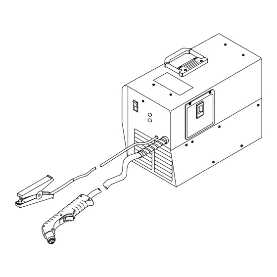
- Page 1 OM-194 473J April 2003 Processes Air Plasma Cutting and Gouging Description Air Plasma Cutter Spectrum Thunder And Ice-12C Torch And Non-CE Models Visit our website at www.MillerWelds.com...
- Page 2 Welding Process Manuals such as SMAW, GTAW, GMAW, and GMAW-P. Miller Electric manufactures a full line of welders and welding related equipment. For information on other quality Miller products, contact your local Miller distributor to receive the latest full line catalog orindividual catalog sheets.
-
Page 3: Table Of Contents
TABLE OF CONTENTS SECTION 1 – SAFETY PRECAUTIONS - READ BEFORE USING ......1-1. Symbol Usage . - Page 4 Declaration of Conformity for European Community (CE) Products NOTE This information is provided for units with CE certification (see rating label on unit). Miller Electric Mfg. Co. Manufacturer’s Name: 1635 W. Spencer Street Manufacturer’s Address: Appleton, WI 54914 USA SPECTRUM...
-
Page 5: Section 1 - Safety Precautions - Read Before Using
SECTION 1 – SAFETY PRECAUTIONS - READ BEFORE USING pom _nd_9/98 1-1. Symbol Usage Means Warning! Watch Out! There are possible hazards with this procedure! The possible hazards are shown in the adjoining symbols. Y Marks a special safety message. This group of symbols means Warning! Watch Out! possible ELECTRIC SHOCK, MOVING PARTS, and HOT PARTS hazards. -
Page 6: Arc Rays Can Burn Eyes And Skin
If inside, ventilate the area and/or use exhaust at the arc to remove EXPLODING PARTS can injure. cutting fumes and gases. If ventilation is poor, use an approved air-supplied respirator. D On inverter power sources, failed parts can ex- Read the Material Safety Data Sheets (MSDSs) and the manufac- plode or cause other parts to explode when turer’s instruction for metals to be cut, coatings, and cleaners. -
Page 7: Additional Symbols For Installation, Operation, And Maintenance
1-3. Additional Symbols For Installation, Operation, And Maintenance HOT PARTS can cause severe burns. FIRE OR EXPLOSION hazard. D Do not touch hot parts bare handed. D Do not locate unit on, over, or near combustible surfaces. D Allow cooling period before working on torch. D Do not install unit near flammables. -
Page 8: Principal Safety Standards
1-4. Principal Safety Standards Safety in Welding and Cutting, ANSI Standard Z49.1, from American Safe Handling of Compressed Gases in Cylinders, CGA Pamphlet P-1, Welding Society, 550 N.W. LeJeune Rd, Miami FL 33126 from Compressed Gas Association, 1235 Jefferson Davis Highway, Suite 501, Arlington, VA 22202. -
Page 9: Section 1 - Consignes De Sécurité - Lire Avant Utilisation
SECTION 1 – CONSIGNES DE SÉCURITÉ – LIRE AVANT UTILISATION pom_nd_fre_5/97 1-1. Signification des symboles Signifie Mise en garde ! Soyez vigilant ! Cette procédure présente des risques de danger ! Ceux-ci sont identifiés par des symboles adjacents aux directives. Y Identifie un message de sécurité... - Page 10 D N’approchez pas le tube du chalumeau et l’arc pilote lorsque la gâchette est D Ne mettez pas votre tête au–dessus des vapeurs. Ne respirez pas ces va- enfoncée. peurs. D Le câble de masse doit être pincé correctement sur la pièce à couper, métal D Si vous êtes à...
-
Page 11: Dangers Supplémentaires En Relation Avec L'installation, Le Fonctionnement Et La Maintenance
1-3. Dangers supplémentaires en relation avec l’installation, le fonctionnement et la maintenance DES PIECES CHAUDES peuvent pro- Risque D’INCENDIE OU voquer des brûlures graves. D’EXPLOSION. D Ne pas toucher des parties chaudes à mains nues. D Ne pas placer l’appareil sur, au-dessus ou à proximité D Laisser refroidir avant d’intervenir sur la torche. -
Page 12: Information Sur Les Champs Électromagnétiques
1-5. Information sur les champs électromagnétiques Données sur le soudage électrique et sur les effets, pour l’organisme, Garder les câbles ensembles en les torsadant ou en les des champs magnétiques basse fréquence attachant avec du ruban adhésif. Mettre tous les câbles du côté opposé de l’opérateur. Le courant de soudage ou de coupage passant dans les câbles de puis- sance crée des causera des champs électromagnétiques. -
Page 13: Section 2 - Definitions
SECTION 2 – DEFINITIONS 2-1. Warning Label Definitions Warning! Watch Out! There are possible hazards as shown by the symbols. Cutting sparks can cause explosion or fire. 1.1 Keep flammables away from cutting. Do not cut near flammables. 1.2 Cutting sparks can cause fires. -
Page 14: Manufacturer's Rating Label For Ce Products
2-2. Manufacturer’s Rating Label For CE Products and CE markings only apply when the torch is used with shielded parts: retaining cup (197 567) and drag shield (196 929). 2-3. Symbols And Definitions Plasma Arc Cutting Adjust Air/Gas Low Air Pressure Amperes (PAC) Pressure... -
Page 15: Section 3 - Installation
SECTION 3 – INSTALLATION 3-1. Specifications For Non-CE Power Sources Max** Primary Primary Primary Service Secondary Secondary Power (DC) Volts Amperes (Recommended) Volts (DC) Amperes Factor 20.32 (0.25*) 2.01 2.44 0.82 *While idling **10% High line condition 3-2. Specifications For CE Power Sources Max** IP Rating (CE Model... -
Page 16: Torch Dimensions And Weight
3-5. Torch Dimensions And Weight 8-3/8 in (213 mm) 1 in (25 mm) 1-3/8 in (35 mm) 3.0 lb (1.4 kg) Ref. 801 397-A 3-6. Selecting A Location 6-3/4 in (171 mm) Dimensions And Weight 17 in 42 lb (19.1 kg) – Non-CE Models (432 mm) 52.3 lb (23.7 kg) –... -
Page 17: Connecting Work Clamp
3-7. Connecting Work Clamp Work Clamp Workpiece Connect work clamp to a clean, paint-free location on workpiece, as close to cutting area as possible. 802 463-A 3-8. Connecting Input Power Check input voltage available at site. Grounded 120 VAC Receptacle (Non-CE Models) A 120 volt, 20 ampere individual branch circuit... -
Page 18: Section 4 - Operation
SECTION 4 – OPERATION 4-1. Controls Power Switch Trouble Light If unit overheats input power is not within specification [93 to 137 vac (non- Power Light Trouble light comes on for the following CE models), 186 to 274 vac (CE conditions: models)]. -
Page 19: Trigger Safety Lock
4-3. Trigger Safety Lock Trigger Trigger Locked Trigger Unlocked 801 545-A OM-194 473 Page 15... -
Page 20: Sequence Of Operation
4-4. Sequence Of Operation EXAMPLE Of Cutting Operation Moisture from the compressor will form in the air line and at the torch. It will be normal to sometimes see moisture come out the end of the torch. The pilot arc starts immediately when trigger is pressed. For shielded cutting, place drag shield on edge Raise trigger lock and press After cutting arc starts, slowly... -
Page 21: Section 5 - Maintenance & Troubleshooting
SECTION 5 – MAINTENANCE & TROUBLESHOOTING 5-1. Routine Maintenance Y Disconnect power Maintain more often before maintaining. during severe conditions. Each Use Check Torch Tip, Electrode, And Shield Every Week Check Shield Cup Shutdown System 3 Months Replace Damaged Or Unreadable Labels Replace... -
Page 22: Overload Protection: Trouble Light And Checking Shield Cup Shutdown System
5-2. Overload Protection: Trouble Light And Checking Shield Cup Shutdown System If certain problems occur, the trouble light comes on, and output stops. Trouble Light Lights if shield cup is loose. Turn power Off, and check shield cup connection (see Item 2 below). Power must be reset whenever the cup shutdown is activated. -
Page 23: Torch And Work Cable Connections
5-3. Torch And Work Cable Connections If torch or work cable needs to be removed or replaced, proceed as follows: Turn power Off, and disconnect input power plug from receptacle. Remove wrapper from unit. Torch Connections Remove existing torch cable from unit. -
Page 24: Checking/Replacing Retaining Cup, Tip, And Electrode
5-4. Checking/Replacing Retaining Cup, Tip, And Electrode Overtightening will strip threads. Do not overtighten retaining cup during assembly. Do not cross-thread parts causing stripping. Use care during torch assembly and parts replacement. Inspect shield cup, tip, and electrode for wear before cutting or whenever cutting speed has been significantly reduced. -
Page 25: Troubleshooting Power Source
5-5. Troubleshooting Power Source Press torch trigger and listen compressor Is input power operation. Check Connect unit to proper input connected to Is compressor Postflow air at torch. Check voltage. (see Section 3-8). operating? correct line Control board PC1, voltage? compressor filter, compressor connections to... -
Page 26: Troubleshooting Torch
5-6. Troubleshooting Torch Torch travel speed too slow; increase travel speed (see Section 4-2). Clean Does arc go replace torch consumables Go to Section 5-5. as necessary (see Section while cutting? 5-4). Be sure work clamp is securely attached workpiece. Be sure work clamp is securely attached to work- piece. -
Page 27: Section 6 - Electrical Diagram
SECTION 6 – ELECTRICAL DIAGRAM 202 707 Figure 5-1. Circuit Diagram For 120 Volts AC Power Source (Non-CE Models) OM-194 473 Page 23... - Page 28 202 701 Figure 5-2. Circuit Diagram For 230 Volts AC Power Source (CE Models) OM-194 473 Page 24...
- Page 29 Notes OM-194 473 Page 25...
-
Page 30: Section 7 - Parts List
SECTION 7 – PARTS LIST Hardware is common and not available unless listed. 802 462-D Figure 6-1. Main Assembly OM-194 473 Page 26... - Page 31 Item Dia. Part Mkgs. Description Quantity Figure 6-1. Main Assembly ....+206 302 WRAPPER ............
-
Page 32: Warranty
Item Part Description 183 427 Handle Assy, left and right w/screws (1) 171 248 Pushbutton Switch (1) 196 931 Leads, 20ft (1) 196 930 Label, ICE-12C (1) 196 932 Main Body (1) 185 833 Switch Assy w/Spring (1) 190 220 Spring, trigger assy (1) 169 231 Grease, silicone (1) - Page 33 Notes...
- Page 34 Notes...
- Page 35 Call LIMITED WARRANTY – Subject to the terms and conditions APT, ZIPCUT & PLAZCUT Model Plasma Cutting below, Miller Electric Mfg. Co., Appleton, Wisconsin, warrants Torches 1-800-4-A-MILLER to its original retail purchaser that new Miller equipment sold...
- Page 36 FAX: 44 (0) 1204-598066 www.MillerWelds.com Contact the Delivering Carrier to: File a claim for loss or damage during shipment. For assistance in filing or settling claims, contact your distributor and/or equipment manufacturer’s Transportation Department. PRINTED IN USA 2003 Miller Electric Mfg. Co. 1/03...
Need help?
Do you have a question about the Spectrum Thunder and is the answer not in the manual?
Questions and answers