Table of Contents
Advertisement
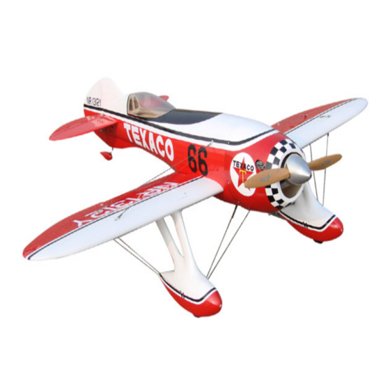
Gee Bee R3
95% Almost-ready-to-fly, and easy to fly
Instruction Manual
Congratulations on your purchase of this excellent almost-ready-to-fly
R/C model! Our airplane has been designed by expert engineers and built
by skilled craftsmen. Many of the parts have been factory-assembled and
installed for you, yet your ultimate success or failure depends on you. Be
sure you have read and understand the entire manual before attempting to
assemble, set up and fly the model.
- - - -
WARNING
THIS IS NOT A TOY!
Radio controlled model aircraft are capable of inflicting serious injury
and /or property damage if not assembled, operated and maintained in a
competent and safe manner. The successful assembly, operation and
1
Advertisement
Table of Contents

Related Manuals for HobbyKing Gee Bee R3


Summary of Contents for HobbyKing Gee Bee R3
-
Page 1: Instruction Manual
Gee Bee R3 95% Almost-ready-to-fly, and easy to fly Instruction Manual Congratulations on your purchase of this excellent almost-ready-to-fly R/C model! Our airplane has been designed by expert engineers and built by skilled craftsmen. Many of the parts have been factory-assembled and installed for you, yet your ultimate success or failure depends on you. -
Page 2: Warranty
maintenance of radio controlled model aircraft are not intuitive skills and performing them safely and competently takes experience. If you are not already an experienced radio controlled aircraft assembler and flyer, we strongly suggest that you find an experienced modeler to assist you. WARRANTY We guarantee this kit to be free from defects in material and workmanship at the time of purchase. -
Page 3: Parts List
Parts List Bag No. Description Qty. Fibregrass Engine Cowl PVC Canopy Self-tapping screws(Φ2×6) 6pcs Self-tapping screws(Φ2×12) 2pcs Screws(Φ2×15) 2pcs M2 Solider clevis 4pcs Steel wire connector 4pcs Copper tube 8pcs Link for wire 4pcs M2 washer M2 nut 2pcs Wheel Gear Landing 1set Self-tapping screws(Φ2×6) 2pcs... - Page 4 Self-tapping screws 12pcs Hinge 6pcs Plastic clevis 2pcs Solider clevis 8pcs Connector 2pcs Steel wire connector 8pcs Copper tube 8pcs Steel wires 4pcs Aluminum wing tube 1pcs Aluminium plate Plastic clip 2pcs Plastic Clevis 1pcs Plastic horn 2pcs Hinges 6pcs Connector 2pcs Pushrod for Elevator(“Y”...
- Page 5 Nuts 8pcs Engine Mount 2pcs Servo box for throttle Pushrod for throttle Plywood plate for cowling Motor mount...
-
Page 6: Assembly Instruction
ASSEMBLY INSTRUCTION Step 1. Installation in the wings 1. Glue the aileron hinges in place Take out the wings and ailerons, insert the hinges into the factory cut hinges slots in the wings and ailerons. Careful to glue them together by dropping CA into the gap at the location of each hinge. - Page 7 Step 2. Installation Landing gear 1. Notice that the mounting flange of the wheel pant has a plywood mounting pad installed at the front and rear. Drill a hole through the center of each pad. Also cut through the mounting flange just above the slot in the side of each pant.
- Page 8 holes with the center of the rubber mounting pads in the wing. Drill a pilot hole through the mounting holes in the pant, through the rubber into plywood underneath. Step3. Assemble the tail surfaces 1. Bolt the wing onto the fuselage and set the airplane in a position so that sight...
- Page 9 4.Hold the bracket over the rear end of the fuselage and drill holes through the front and rear mounting holes. Screw the bracket in place with washer head self-tapping screws provider. Push the wheel collar up under the bracket and tighten the setscrew to hold it in place.
- Page 10 Step4. Install the engine 1. Firstly, try fit the engine cowl to the fuselage head. Using a straight ruler, insert it through the front opening of the cowl until it touches firewall. Thus, you can measure the distance D between the front edge of the cowl and the firewall.
- Page 11 Step5. Mount the Receiver and Battery onto the fuselage 1. Fit the battery on the battery rack on the bottom of fuselage, and bundle tightly with Velcro strap. Please note the position of battery in the fuselage should be base on the C.G point.
- Page 12 properly at the trailing edge. Take the wings apart and rough up the surface of one of the dowel with a course file or a cut-off wheel. Finally, with 6pcs self-tapping screws mount the canopy in place on the cockpit. At last, adjust the wing and fuselage configuration as in the diagrams carefully.
- Page 13 Step 7. Final check before flying You have finished your model airplane, but you have to check before flying. 1. Check the alignment and trim of the airplane after final assembly. 2. Check that everything is tightly securely. 3. Check the C.G. point, which must be 83mm (3.27 in.) behind the leading edge measured at the center of the upper wing center section.
Need help?
Do you have a question about the Gee Bee R3 and is the answer not in the manual?
Questions and answers