Sign In
Upload
Manuals
Brands
Honeywell Manuals
Recording Equipment
DR4500A
Honeywell DR4500A Manuals
Manuals and User Guides for Honeywell DR4500A. We have
4
Honeywell DR4500A manuals available for free PDF download: Product Manual, Kit Instruction, Kit Instructions, Quick Start Manual
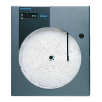
Honeywell DR4500A Product Manual (266 pages)
Classic Series Circular Chart Recorder With or Without Control
Brand:
Honeywell
| Category:
Recording Equipment
| Size: 4.27 MB
Table of Contents
Symbol Definitions
5
Table of Contents
6
1 Overview
15
Introduction
15
Operator Interface
17
Figure 1-1 Operator Interface
17
Table 1-1 Function of Keys
18
Set-Up Tasks
19
Figure 1-2 Set-Up Tasks
19
2 Installation
21
Overview
21
Table 2-1 Operating Limits and Condensed Specifications
22
Model Number Interpretation
27
Figure 2-1 Model Number Interpretation
27
Table 2-2 Procedure to Access Components
28
Figure 2-2 DR4500A Recorder Hardware Components Versus "Table" Selections
29
Mounting Considerations and Overall Dimensions
30
Figure 2-3 Overall Dimensions
30
Mounting Methods
31
Figure 2-4 How to Remove Knockouts
31
Table 2-3 Mounting Flush in a New Panel Cutout
32
Figure 2-5 Mounting Flush in a New Panel Cutout
32
Table 2-4 Reference Data for Mounting DR4500A in Existing Panel Cutouts
33
Table 2-5 Mounting Flush in a Panel Using Universal Filler Kit
34
Figure 2-6 Mounting in a Panel Using Universal Filler Kit
34
Table 2-6 Mounting Flush in a Panel Using Kent Model 105M Cutout
35
Figure 2-7 Mounting in a Panel Using Kent Model 105M Cutout
35
Table 2-7 Procedure for Mounting Recorder with NEMA4X Door
36
Figure 2-8 Panel Mounting Recorder with NEMA4X Door
37
Table 2-8 Pipe Mounting Procedure
38
Figure 2-9 Pipe Mounting Brackets
38
Table 2-9 Mounting Flush on a Surface (of Panel or Wall)
39
Figure 2-10 Mounting Flush on a Surface (of Panel or Wall)
40
Wiring Prerequisites
41
Table 2-10 Permissible Wiring Bundling
42
Input Wiring Procedures
43
Figure 2-11 Ferrite Filter Locations and Shield Wiring (CE Mark)
44
Table 2-11 AC Line Power Wiring
45
Figure 2-12 AC Line Power Wiring
46
Table 2-12 Thermocouple, RTD, Radiamatic, MV, or 0-5 VDC Input Wiring
47
Figure 2-13 Thermocouple, RTD, Radiamatic, MV, or 0-5 VDC Input Wiring
48
Table 2-13 4-20 Ma Input Wiring
49
Figure 2-14 4-20 Ma Input Wiring
50
Table 2-14 0-10 Volt DC Input Wiring
51
Figure 2-15 0-10 Volt DC Input Wiring
52
Output Wiring Procedures
53
Table 2-15 4-20 Ma Control Output Wiring
53
Figure 2-16 4-20 Ma Control Output Wiring (or Aux out #2 and #3 Wiring)
54
Table 2-16 Position Proportional Control Output Wiring
55
Figure 2-17 Position Proportional Control Output Wiring
56
Table 2-17 Relay Control Output Wiring
57
Figure 2-18 Relay Control Output Wiring
58
Option Wiring Procedures
59
Table 2-18 Alarm Output or Digital Input Wiring
59
Figure 2-19 Alarm Output or Digital Input Wiring
60
Table 2-19 Alarm 3 and Alarm 4 Output Wiring
61
Table 2-20 Alarm 5 and Alarm 6 Output Wiring
62
Figure 2-20 Alarm Outputs #3, 4, 5, and 6 Wiring
63
Table 2-21 RS485 Modbus Communications Wiring
64
Figure 2-21 RS485 Modbus Communications Wiring
65
Table 2-22 4-20 Ma Auxiliary Output Wiring
66
Figure 2-22 4-20 Ma Auxiliary Output Wiring
67
Lockout Switch Configuration
68
Figure 2-23 S1 Lockout Switch Location
68
3 Configuration
69
Overview
69
Configuration Prompts
70
Figure 3-1 DR4500A Prompt Hierarchy
70
How to Get Started
72
Configuration Tips
73
Table 3-1 Configuration Tips
73
Configuration Procedure
74
Table 3-2 Configuration Procedure
74
Input Set up Group
76
Table 3-3 Input Group Function Prompts
76
Pen Set up Group
78
Table 3-4 Pen 1 or 2 Group Function Prompts
78
Chart Set up Group
79
Table 3-5 Chart Group Function Prompts
79
Totalizer Set up Group
80
Table 3-6 Totalizer Group Function Prompts
80
Control Set up Group
81
Table 3-7 Control 1 or Control 2 Group Function Prompts
81
Tuning Parameters Set up Group
83
Table 3-8 Tuning 1 or Tuning 2 Group Function Prompts
83
SP Ramp Set up Groups
84
Table 3-9 SP Ramp 1 or 2 Group Function Prompts
84
Timer Set up Group
85
Table 3-10 Timer Group Function Prompts
85
Alarms Set up Group
86
Table 3-11 Priority of Functions that Operate Relays
86
Table 3-12 Alarms Group Function Prompts
87
Auxiliary Output Set up Group
88
Table 3-13 Auxiliary Output Group Function Prompts
88
Modbus Communications Set up Group
89
Table 3-14 Modbus Communications Group Function Prompts
89
Options Set up Group
90
Table 3-15 Options Group Function Prompts
90
April
90
Lockout Set up Group
91
Table 3-16 Lockout Group Function Prompts
91
Configuration Record Sheet
92
4 Configuration Parameter Definitions
95
Overview
95
Input Parameters Set up Group
96
Table 4-1 Input Group Definitions
96
Pen Parameters Set up Group
100
Table 4-2 Pen 1 or 2 Group Definitions
100
Chart Parameters Set up Group
102
Table 4-3 Chart Parameters Group Definitions
102
Total Parameters Set up Group
103
Table 4-4 Totalizer Group Definitions
103
Control Parameters Set up Group
105
Table 4-5 Control 1 or 2 Group Definitions
105
Tuning Parameters Set up Group
114
Table 4-6 Tuning Group Prompt Definitions
114
Setpoint Ramp Set up Group
117
Table 4-7 Setpoint Ramp 1 or 2 Group Definitions
117
Timer Set up Group
119
Table 4-8 Timer Group Definitions
119
Alarms Set up Group
120
Table 4-9 Priority of Functions that Operate Relays
120
Table 4-10 Alarms Group Definitions
121
Auxiliary Output Set up Group
123
Table 4-11 Auxiliary Output Group Definitions
123
Modbus Communications Set up Group
125
Table 4-12 Modbus Communications Group Definitions
125
Options Set up Group
126
Table 4-13 Option Group Definitions
126
April
127
Lockout Parameters Set up Group
128
DR4500A Classic Series Circular Chart Recorder with or Without Control Product Manual Release M
128
Table 4-14 Lockout Group Definitions
128
5 Operation
129
Overview
129
Preparation
130
Table 5-1 Install/Replace Chart
130
Figure 5-1 Basic Recording Components
131
Start-Up
132
Table 5-2 Set the Chart Time Line Procedure
132
Table 5-3 Power up Diagnostic Tests
132
Table 5-4 Procedure for Testing the Displays and Keys
133
Table 5-5 Procedure for Starting up the Recorder
134
Monitoring Your Recorder
135
Figure 5-2 Operator Interface
136
Table 5-6 Meaning of Indicators
137
Figure 5-3 Deviation Bargraph
138
Table 5-7 Lower Display Key Parameter Prompts
139
Table 5-8 Error Messages
140
Table 5-9 Alarm and Tuning Messages
141
Operator Functions
142
Operating Modes
143
Table 5-10 Operating Mode Definitions
143
Table 5-11 Changing Operating Modes
143
Table 5-12 Procedure for Selecting Automatic or Manual Mode
144
Setpoints
145
Table 5-13 Procedure for Selecting the Setpoint Source
145
Table 5-14 Procedure for Changing the Local Setpoint
145
Table 5-15 Procedure for Switching between Setpoints
146
Table 5-16 Setpoint Selection Indication
146
Single Setpoint Ramp
147
Table 5-17 Procedure for Configuring a Single Setpoint Ramp
147
Table 5-18 Procedure for Running a Setpoint Ramp
148
Using Two Sets of Tuning Constants (PID Values)
150
Table 5-19 Procedure for Selecting Two Sets of Tuning Constants
150
Table 5-20 Procedure for Setting Switchover Values
151
Table 5-21 Procedure for Setting Tuning Constant Values
151
Table 5-22 Procedure for Switching PID Sets from the Keyboard
152
Using Accutune II
153
Table 5-23 Procedure for Starting Accutune II
153
Table 5-24 Procedure for Using Accutune for Duplex Control
154
Alarm Setpoints
156
Table 5-25 Procedure for Displaying or Changing the Alarm Setpoints
156
Digital Input Option (Remote Switching)
157
Table 5-26 Digital Input Option Action on Contact Closure
157
Resetting and Displaying Totalizer Value
158
Table 5-27 Procedure for Resetting the Totalizer
158
Table 5-28 Procedure for Displaying the Totalizer Value
159
Monitoring the External Event Operation
160
Maximizing Pen Life
160
Table 5-29 Maximizing Pen Life
160
Routine Maintenance
161
Table 5-30 Changing the Ink Cartridge
161
Table 5-31 Replacing a Chart Lamp
161
Installing/Replacing Chart
162
April
162
6 Setpoint Ramp/Soak Programming and Operation
163
Overview
163
Setpoint Program Contents
165
Drawing a Ramp/Soak Profile
168
Figure 6-1 Ramp/Soak Profile Example
168
Table 6-1 Parameter Settings for Example 12-Step Profile
169
Entering the Setpoint Program Data
173
Table 6-2 Setpoint Program Data Entry Procedure
173
SP RAMP1 and SP RAMP2 Set up Group
175
Table 6-3 SP RAMP Prompts and Available Selections
175
Setpoint Program Profiles Set up Group
177
Table 6-4 Setpoint Program Profiles Group Definitions
177
Setpoint Program Segments Set up Group
179
Table 6-5 Setpoint Program Segments Group Definitions
179
Setpoint Program Event Set up Group
182
Table 6-6 Setpoint Program Event Group Definitions
182
Table 6-7 Segment Event Relay Operation Requirements
183
Run/Monitor the Program
186
Table 6-8 Run/Monitor Functions
186
7 Input Calibration
189
Overview
189
Restoring Factory Calibration
190
Table 7-1 Restoring Factory Calibration
190
Minimum and Maximum Range Values
192
Table 7-2 Voltage and Resistance Equivalents for 0% and 100% Range Values
192
Preliminary Information
194
Table 7-3 Disconnect the Field Wiring
194
Figure 7-1 Location of the Input Connections on the Input Boards
194
Table 7-4 Equipment Needed
195
Calibration Set up and Wiring for PV Inputs
196
Figure 7-2 Location of Jumper Positions W1/MA and W3 on the Input Boards
196
Table 7-5 General Set up Procedure
197
Table 7-6 Set up Wiring Procedure for Thermocouple Inputs Using an Ice Bath
198
Figure 7-3 Calibration Set up Diagram for Thermocouple Inputs Using an Ice Bath
198
Table 7-7 Set up Wiring Procedure for Thermocouple Inputs Using a Compensated Calibrator Method
199
Figure 7-4 Calibration Set up Diagram for Thermocouple Inputs Using a Compensated Calibrator Method
199
Table 7-8 Set up Wiring Procedure for Thermocouple Inputs Using the Ambient Temperature Method
200
Figure 7-5 Calibration Set up Diagram for Thermocouple Inputs Using the Ambient Temperature Method
200
Table 7-9 Set up Wiring Procedure for RTD Inputs
201
Figure 7-6 Calibration Set up Diagram for RTD Inputs
201
Table 7-10 Set up Wiring Procedure for Radiamatic, Millivolts, and Volts Inputs (Except 0-10 Volts)
202
Figure 7-7 Calibration Set up Diagram for Radiamatic, Millivolts, and Volts Inputs (Except 0-10 Volts)
202
Table 7-11 Set up Wiring Procedure for 0-10 Volt Inputs
203
Figure 7-8 Calibration Set up Diagram for 0-10 Volt Inputs
203
Table 7-12 Set up Wiring Procedure for 4-20 Ma Inputs
204
Figure 7-9 Calibration Set up Diagram for 4-20 Ma Inputs
204
Calibration Procedure
205
Table 7-13 Calibration Procedure Sequence
205
8 Output Calibration
208
Overview
208
Current Proportional Output/Aux out 2 and 3 Calibration
209
Table 8-1 Set up Wiring Procedure Current Proportional Output/Aux out 2 and 3
209
Figure 8-1 Test Equipment Connections for Calibrating Current Proportional Output
209
Table 8-2 Current Proportional Output/Aux out 2 and 3 Calibration Procedure
210
Position Proportional Output Calibration
211
Table 8-3 Position Proportional Output Calibration Procedure
212
Auxiliary Output Calibration
214
Table 8-4 Set up Wiring Procedure for Auxiliary Output
214
Figure 8-2 Test Equipment Connections for Calibrating Auxiliary Output
214
Table 8-5 Auxiliary Output Calibration Procedure
215
9 Troubleshooting / Service
216
Overview
216
Troubleshooting Aids
218
Table 9-1 Procedure for Identifying the Software Version
219
Self Diagnostics
220
Table 9-2 Power-Up Tests
220
Table 9-3 Procedure for Displaying the Device Status
221
Table 9-4 Error Message Prompts
222
Visual Failure Symptoms
226
Table 9-5 Visual Failure Symptoms
226
Troubleshooting Procedures
227
Table 9-6 Procedure #1-Troubleshooting Recorder Failure Symptoms
227
Table 9-7 Procedure #2-Troubleshooting Pen Trace Failure Symptoms
228
Table 9-8 Procedure #3-Troubleshooting Chart Rotation Failure Symptoms
228
Table 9-9 Procedure #4-Troubleshooting Erratic Pen Movement Symptoms
229
Table 9-10 Procedure #5-Troubleshooting Pen Failure Symptoms
229
Table 9-11 Procedure #6-Troubleshooting Keyboard And/Or Display Failure Symptoms
229
Table 9-12 Procedure #7-Troubleshooting Current Proportional Output Failure Symptoms
230
Table 9-13 Procedure #8-Troubleshooting Position Proportional Output Failure Symptoms
230
Table 9-14 Procedure #9-Troubleshooting Relay Output Failure Symptoms
231
Table 9-15 Procedure #10-Troubleshooting Current/Time or Time/Current Failure Symptoms
231
Table 9-16 Procedure #11-Troubleshooting the Auxiliary Output
232
Table 9-17 Procedure #12-Troubleshooting External Alarm Function Failure Symptoms
232
Table 9-18 Procedure #13-Troubleshooting Modbus Communications Failure Symptoms
232
Pen Alignment
233
Table 9-19 Pen 1 (Purple) and Pen 2 (Red) Mechanical Alignment
233
Figure 9-1 Mechanical Alignment of Pens
234
Table 9-20 Set the Chart Time Line Procedure
235
April
235
10 Parts List
236
Overview
236
Figure 10-1 Door Assembly
236
Figure 10-2 Chart Plate Assembly
236
Figure 10-3 Basic Recorder Components Without Options
236
Figure 10-4 Recorder Components Associated with Options
236
Exploded Views
237
Table 10-1 Door Assembly Parts
237
Table 10-2 Chart Plate Assembly Parts
239
Table 10-3 Basic Recorder Parts Without Options
241
Table 10-4 Recorder Parts Associated with Options
243
Miscellaneous Hardware Kit Contents
244
Table 10-5 Miscellaneous Hardware Kit
244
April
245
Internal Cabling Data - Without Options
246
Figure 10-5 Internal Cabling for DR4500A Classic Recorder
246
Internal Wiring Diagram - Options Only
247
Figure 10-6 Internal Diagram for DR4500A Classic Recorder - Options Only
247
Foreign Language Safety Instructions
249
Da2I-6057
250
Du2I-6057
251
Fi2I-6057
252
Fr2I-6057
253
Ge2I-6057
254
Gr2I-6057
255
It2I-6057
256
No2I-6057
257
Po2I-6057
258
Sp2I-6057
259
Sw2I-6057
260
Index
261
April
262
Advertisement
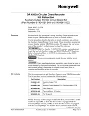
Honeywell DR4500A Kit Instruction (8 pages)
Circular Chart Recorder
Brand:
Honeywell
| Category:
Voice Recorder
| Size: 0.07 MB
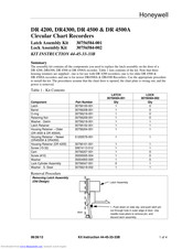
Honeywell DR4500A Kit Instructions (5 pages)
Circular Chart Recorders
Brand:
Honeywell
| Category:
Voice Recorder
| Size: 0.03 MB
Advertisement
Honeywell DR4500A Quick Start Manual (2 pages)
Circular Chart Recorder Kit, Chart Plate Lockout Kit
Brand:
Honeywell
| Category:
Voice Recorder
| Size: 0.1 MB
Advertisement
Related Products
Honeywell DR4300 Series
Honeywell DR4500
Honeywell DR4301
Honeywell DR4302
Honeywell DR4322
Honeywell DR4321
Honeywell DR4311
Honeywell DR4312
Honeywell DR4332
Honeywell DR4331
Honeywell Categories
Thermostat
Controller
Control Unit
Security Camera
Accessories
More Honeywell Manuals
Login
Sign In
OR
Sign in with Facebook
Sign in with Google
Upload manual
Upload from disk
Upload from URL