Table of Contents
Advertisement
Quick Links
Safety Precautions
FOR USA AND CANADA
RISK OF ELECTRIC SHOCK
DO NOT OPEN
CAUTION: TO REDUCE THE RISK OF ELECTRIC SHOCK, DO
NOT REMOVE COVER (OR BACK).
NO USER-SERVICEABLE PARTS INSIDE. REFER
SERVICING TO QUALIFIED SERVICE PERSONNEL.
Symbol Meanings:
This symbol on the equipment refers you to
important operating and maintenance (servicing)
instructions within the Product Manual
Documentation. Failure to heed this information may
present a major risk of damage or injury to persons
or equipment.
Warning -The symbol with the word "Warning"
within the equipment manual indicates a potentially
hazardous situation, which if not avoided, could
result in death or serious injury.
Caution - The symbol with the word "Caution" within
the equipment manual indicates a potentially
hazardous situation, which if not avoided, may result
in minor or moderate injury. It may also be used to
alert against unsafe practices.
Notice - The symbol with the word "Notice" within
the equipment manual indicates a situation, which if
not avoided, may result in major or minor equipment
damage or a situation, which could place the
equipment in a non-compliant operating state.
Warning Hazardous Voltages - This symbol is
intended to alert the user to the presence of
uninsulated "dangerous voltage" within the product
enclosure that may be of sufficient magnitude to
constitute a risk of shock to persons.
ESD Susceptibility - This symbol is used to alert the
user that an electrical or electronic device or
assembly is susceptible to damage from an ESD
event.
US
FCC Part 15 Subpart B
This equipment has been tested and found to comply with the
limits for a class A Digital device, pursuant to part 15 of the FCC
Rules. These limits are designed to provide reasonable
protection against harmful interference when the equipment is
operated in a commercial environment. This equipment
generates, uses, and can radiate radio frequency energy and, if
not installed and used in accordance with the instruction manual,
may cause harmful interference to radio communications.
Operation of this equipment in a residential area is likely to cause
harmful interference in which case the user will be required to
correct the interference at his own expense.
Notice - Changes or modifications to this equipment
not expressly approved by JVC could void the user's
authority to operate this equipment.
Notice - The rating plate (serial number plate) is on
this unit.
WARNING - TO REDUCE THE RISK OF FIRE OR
ELECTRIC SHOCK, DO NOT EXPOSE THIS
APPLIANCE TO RAIN OR MOISTURE.
THIS DEVICE COMPLIES WITH PART 15 OF THE FCC
RULES. OPERATION IS SUBJECT TO THE FOLLOWING TWO
CONDITIONS: (1) THIS DEVICE MAY NOT CAUSE HARMFUL
INTERFERENCE, AND (2) THIS DEVICE MUST ACCEPT ANY
INTERFERENCE RECEIVED, INCLUDING INTERFERENCE
THAT MAY CAUSE UNDESIRED OPERATION.
This unit should be used with 12 V DC only.
CAUTION
CANADA
This Class "A" digital apparatus complies with Canadian
ICES-003.
Cet appareil numerique de la classe "A" est conforme a la norme
NMB-003 du Canada.
WARNING - TO REDUCE THE RISK OF FIRE OR
ELECTRIC SHOCK, DO NOT EXPOSE THIS
APPLIANCE TO RAIN OR MOISTURE.
This unit should be used with 12V DC only.
CAUTION - To prevent electric shocks and fire
hazards, do NOT use any other power source.
AVERTISSEMENT - POUR EVITER LES RISQUES
D'INCENDIE OU D'ELECTROCUTION, NE PAS
EXPOSER L'APPAREIL A L'HUMIDITE OU A LA
PLUIE.
Ce magnétoscope ne doit être utilizé que sur du courant direct en
12V.
ATTENTION - Afin d'eviter tout resque d'incendie ou
d'electrocution, ne pas utiliser d'autres sources
d'alimentation électrique.
Notice - The rating plate (serial number plate) is on
this unit.
REMARQUE - Le plaque signalétique (plaque du
numéro desérie) es située sur le cadre intérieur de
l'unité.
CAUTION - To prevent electric shock, do not open
the cabinet. No user serviceable parts inside. Refer
servicing to qualified service personnel.
EUROPE
This equipment is in compliance with the essential requirements
and other relevant provisions of CE Directive 93/68/EEC.
INTERNATIONAL
This equipment has been tested to CISPR 22:1997 along with
amendments A1:2000 and A2:2002 and found to comply with the
limits for a Class A Digital device.
Notice - This is a Class A product. In domestic
environments this product may cause radio
interference in which case the user may have to take
adequate measures.
CAUTION - Where there are strong electromagnetic
waves or magnetism, for example near a radio or TV
transmitter, transformer, motor, etc., the picture and
the sound may be disturbed. In such cases, please
keep the apparatus away from the sources of the
disturbance.
Due to design modifications, data given in this instruction book
are subject to possible change without prior notice.
Dear Customer,
This apparatus is in conformance with the valid European
directives and standards regarding electromagnetic compatibility
and electrical safety.
European representative of Victor Company of Japan, Limited is:
JVC Technical Services Europe GmbH
Postfach 10 05 04
61145 Friedberg
Germany
Advertisement
Table of Contents

Related Manuals for JVC KM-H3000


Summary of Contents for JVC KM-H3000
-
Page 1: Safety Precautions
Notice - Changes or modifications to this equipment the sound may be disturbed. In such cases, please not expressly approved by JVC could void the user's keep the apparatus away from the sources of the authority to operate this equipment. -
Page 2: Environmental Information
Safety Precautions (continued) FOR EUROPE This equipment is in conformity with the provisions and protection requirements of the corresponding European Directives. This equipment is designed for professional video appliances and can be used in the following environments: - Controlled EMC environment (for example, purpose-built broadcasting or recording studio), and rural outdoors environments. -
Page 3: Table Of Contents
Contents Introduction Advanced Operation About This Manual ..........1 Transition Limit........... 29 Documentation Terms..........1 Modifying Wipes..........29 Control Panel Overview.........1 Modifying DVE Transitions........ 30 Control Panel Rear Connections Overview ...2 Using the Memory System ........31 Menu System ............2 Memory AI and Recall to Preview ...... 32 Knobs ..............3 Reset Options............ -
Page 5: Introduction
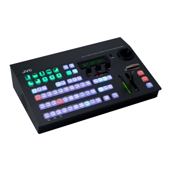
The KM-H2500 and KM-H3000 combine professional Control Panel Overview switcher quality with an easy to use and mobile design. They can be used with other JVC professional products to create professional style The KM-H3000 and KM-H2500 control panels offer broadcasts. -
Page 6: Control Panel Rear Connections Overview
UPGRADE Aux Bus Buttons • Assigns the Key/Aux bus to selected Aux bus Figure 4 KM-H2500 when button is pressed (KM-H3000 only). • Aux bus assignment is done through the menu Power Switch interface on KM-H2500 switchers. • Turns the switcher on and off. -
Page 7: Knobs
To access a menu using the MENU button: To use the knobs: • Rotate the knob to adjust the corresponding value. To default a value using the knobs: Press MENU. The Wipe Pattern buttons • Double-press a knob to default the value currently illuminate. -
Page 8: Shift
Fader handle moves from one limit to the other, the Progress Bar indicates the progress of the transition. Positioner The KM-H3000 has a joystick positioner for positioning wipes, patterns, washes, and DVE effects. The KM-H2500 does not have a positioner. - Page 9 Saturation Saturation affects the vividness of a color. Increasing saturation produces a more vivid color while decreasing saturation produces a less vivid color. Fully decreasing the saturation produces gray.
-
Page 11: Configuration
Configuration This chapter describes how to configure your European Video Formats switcher to meet your requirements. Setup and European switchers support the following video switcher personality options are discussed. formats: • 576i (4:3 and 16:9) at 50Hz Reference Type • 720p at 50 or 59.94Hz •... - Page 12 Understanding Aspect Ratio Conversion • PllrBx — Black bars are added to the right and left of a 4:3 image to display correctly in a 16:9 video Converting between video formats often requires format. converting between aspect ratios. Your switcher supports the following aspect ratio conversion 16:9 methods:...
- Page 13 Use the Fcfs1-4 knob to assign the FCFS video format. No aspect distortion is channel. You can choose from the following: introduced. • LttrBx — Black bars are added to the top and • Off — The FCFS channel is not assigned. bottom of a 16:9 image to display correctly in a •...
-
Page 14: Output Reference Sync
Use the Frming knob to set the aspect ratio To set the output reference sync: conversion mode. You can choose from the following: • Full — The video signal is scaled disproportionately to fill the display of the new aspect ratio. Aspect distortion occurs as the image is stretched/compressed to fit in the new aspect ratio. -
Page 15: Aspect Ratio
10. Press the Confrm knob to commit the change To change the aspect ratio: and exit the Output Sync menu. Press the Cancel knob to return to the Output Sync menu for further editing. Resetting the Output Reference Sync You can quickly reset the output reference sync values to the default settings. -
Page 16: Input Bnc Configuration
KM-H2500 modification. • L Strip — Remove ancillary data and the first few lines of picture from the video signal. KM-H3000 • L Pass — Pass ancillary data and the first few lines of picture. Input BNC Configuration If you are using standard definition sources, use... -
Page 17: Output Configuration
• Aux 1 - 3 — Aux bus 1-3 outputs. refer to the section “Selecting a Special Source for • In 1 - 12 — Inputs 1-12 (KM-H3000 only). the Aux Buses” on page 42. • In 1 - 6 — Inputs 1-6 (KM-H2500 only). -
Page 18: Switcher Personality
To configure a DHCP IP address for your 10 11 12 switcher: Press NEXT until IPAddr is displayed. 10. Use the left knob to select the data to configure. You can choose from the following: • IPAddr — Configure the IP address (configure Ensure your switcher is connected to your this first). - Page 19 Press the AuxMem knob to set the Aux Bus To save a custom Panel Glow color scheme: Recall Mode. You can choose from the following: • NoRcll — Aux buses ignore the input saved with the recalled memory and retain the current input.
- Page 20 Press the Confrm knob to commit the load. Press MENU. Press the Cancel knob to cancel the load. Press the PERS Wipe Pattern button. Power-Save Mode Use the Rate knob to select the units used to specify switcher transition rates. You can choose The switcher goes into a Power-Save mode after a from the following: certain amount of time (20 minutes by default) without...
- Page 21 • KEY1 — DVE channel 2 is locked to Key 1. • KEY2 — DVE channel 2 is locked to Key 2. • KEY3 (KM-H3000 only) — DVE channel 2 is Press MENU. locked to Key 3. • TRANS — DVE channel 2 is locked to Press the SYSTEM Wipe Pattern button.
- Page 22 DVE Resource Capturing Press the FldSwt (FrmSwt if you are using a progressive scan video format) knob to commit Capturing a DVE resource for a new key or transition the selection. takes the DVE resources from the following sources in order of availability: Editor Control •...
- Page 23 Use the Trans knob to set the behavior of the Use the ARKey knob to set whether a Key Next Transition area after a transition is remains or is removed from the Next transition performed. You can choose from the following: area after a dedicated key transition is performed.
-
Page 25: Basic Operation
• KEY 1 • KEY 2 To cut on the Program bus: • KEY 3 (KM-H3000 only) Select the source on the Preset bus (when BKGD is selected as part of the next transition), that you want to take on-air. The selected source appears on your preview monitor. -
Page 26: Configuring The Auto Trans Rate
To perform a wipe transition: Select the source you want to take on-air by pressing a source button on the Program bus. Note: • You can not preview the next source on your preview monitor when cutting on the Program Bus. Configuring the Auto Trans Rate You can control the amount of time a dissolve or wipe transition takes to complete when you press the... -
Page 27: Pausing A Transition
• DVE Key — The video image can be scaled, cropped and freely positioned on the screen. Borders and other effects may be used to enhance the key appearance. The KM-H2500 supports 2 keys. The KM-H3000 supports 3 keys. -
Page 28: Key Transitions
• KEY 2 to include Key 2. Selecting Keys • KEY 3 to include Key 3 (KM-H3000 only). Selecting a key allows you to configure the key type Select a source on the Key/Aux bus that you and select a source for that key. -
Page 29: Dedicated Key Transitions
• Press KEY 1 TRANS to transition Key 1. • Press KEY 2 TRANS to transition Key 2. • Press KEY 3 TRANS to transition Key 3 (KM-H3000 only). Note: • When a key is on-air, the appropriate dedicated Select the key you wish to use. -
Page 30: Dve Key
• Magenta For More Information on... • selecting Keys, refer to the section “Selecting Press Init. Keys” on page 24. For More Information on... • DVE Resource sharing, refer to the section • selecting Keys, refer to the section “Selecting “Resource Sharing”... - Page 31 For More Information on... Note: • accessing an Aux bus, refer to the section “Aux • If the wash is turned off, the pattern does not Buses” on page 41. display. To select a matte color by loading a preset: •...
-
Page 32: Fade To Black
Fade to Black Fade to Black is achieved by selecting the black source and performing a transition. To fade to black: Press BKGD and all on-air key buttons simultaneously to include them in the transition. Select a transition type. Press BLACK/MATTE on the Preset bus. Fade to black by sliding the Fader, pressing CUT, or pressing AUTO TRANS. -
Page 33: Advanced Operation
Advanced Operation This chapter describes advanced operating concepts To continue the transition, press the Limit knob for your switcher. Advanced topics and information on to turn off the transition limit. modifying basic concepts to fit your requirements are Press AUTO TRANS to complete the transition. discussed. -
Page 34: Modifying Dve Transitions
• The X Pos and Y Pos can be adjusted using the • Disabled — DVE transitions always run in the positioner (KM-H3000 only). direction specified in step 4 above. • Aspect adjustments are not available for all To select a DVE effect for a transition: patterns. -
Page 35: Using The Memory System
Note: Press STORE. • You can also select an effect by pressing the Press NEXT. Pattern buttons as follows: Press the right knob to toggle between memory access modes. You can choose from the Table 1 DVE Effect Selection following: Pattern Single Press Pattern Double Press Pattern... -
Page 36: Memory Ai And Recall To Preview
To recall a setting from a memory register: Select the memory register you wish to recall from as follows: • If you are using Bank Mode, select a pattern button to designate the memory register in the selected bank. You may also use the Bank knob to change the selected bank before storing. - Page 37 (on-air image is not affected). Table 2 Recall to Preview Scenarios › KM-H3000: Input 5 is recalled to Key 3 as Key 2 Scenario Memory is now in-use (on-air image is not affected).
-
Page 38: Reset Options
Note: Reset Options • Default transition rates vary depending on the frequency of the selected video format. You can restore the entire switcher or individual settings to default values. Menu items can also be Configuring Default Settings reset. You can customize any of the default parameters and You can also capture the state of the switcher as a save them as a user-defined default. - Page 39 Press the Confrm knob to commit the change. To reset Key 1: Press the Cancel knob to cancel the change and Press and hold down CHR KEY, AUTO SELECT, return to the previous setting. or DVE. Resetting the Switcher Press the RESET Wipe Pattern button. Resetting the switcher restores the user-defined Note: default settings..
-
Page 40: Usb Storage
To restore factory defaults: Press NEXT to cycle through the sets. Press the knob for the set you want to save the memory registers to. Use the left knob to select which memory registers you wish to save. You can choose from the following: •... -
Page 41: Software Upgrades
Insert a USB drive into the USB port. Software Upgrades Press MENU. Press the LOAD Wipe Pattern button. Software upgrades stored on a USB drive can be uploaded to the switcher. Press the Mems knob to display the Load Memory menu. To upgrade the switcher software: Press NEXT to cycle through the sets. -
Page 42: Advanced Keying
Note: To modify the transparency: • Wait 5 seconds after inserting a USB drive into the USB port before using it. • Turn the middle knob when browsing the file system to display the full text of long directory lists and filenames. - Page 43 To modify a mask: To modify the clip or gain: Select the key you wish to modify. Select the key you wish to modify. If necessary, press KEY 1, KEY 2, or KEY 3 to If necessary, press KEY 1, KEY 2, or KEY 3 to include the key in the next transition and have it include the key in the next transition and have it display on the Preview monitor.
- Page 44 The Gain effect controls color saturation. Increasing Select the key you wish to modify (ensure it is set the Gain causes the video signal colors to become as a DVE key). increasingly saturated and vivid. Decreasing the Gain Use the X Pos knob or the positioner to control decreases the saturation until the image is black and the horizontal location of the key image.
-
Page 45: Aux Buses
Note: Accessing the Aux Buses • Split Keys are initially created with clip set to 50% KM-H3000: The Aux buses can be accessed from and gain set to 50%. control panel buttons. • While holding the AUTO SELECT button to select... -
Page 46: Tallies
Select the desired Aux bus by pressing AUX 1 - Figure 1 Tally Port Selecting a Source for the Aux Buses Once an Aux bus has been selected, you can change Input the source. To select a source for an Aux bus: Select the Aux bus you wish to choose a source Press the desired source button on the Key/Aux bus. -
Page 47: General Purpose Interface (Gpi)
For More Information on... General Purpose Interface (GPI) • port locations, refer to the section “Control Panel Rear Connections Overview” on page 2 The switcher has 24 GPI inputs that are used to trigger memory recalls, transitions, and Aux bus input Editor Port changes. -
Page 49: Media-Store
Media-Store This chapter describes the Media-Store operation. For More Information on... Your switcher has 2 Media-Store channels which • Associating alpha channel inputs with video inputs, allow you to display 2 images or animations refer to the section “Input BNC Configuration” on (composed of a sequence of images) on-air page 12. -
Page 50: Understanding Media Numbers
knob to load it into the selected Media-Store Press and hold SHIFT on any bus. If you use the channel. Program bus or on-air Key bus, you may affect on-air images. Note: Press MEDIA 1 or MEDIA 2 to select a •... -
Page 51: Modifying Media-Store Image Attributes
Note: • You can use the positioner to modify the X and Y position (KM-H3000 only). If you are loading an image from a USB drive, To change an image between shaped and insert it into the USB port on the switcher. -
Page 52: Animation Control
To change the Media number for an image: Modifying Animation Playback You can set an animation to playback automatically as well as control playback speed and direction. To modify animation playback: Press and hold SHIFT on any bus. If you use the Program bus or on-air Key bus, you will affect on-air images. - Page 53 To save attributes for an image: Modify the attributes for an image as necessary Use the Func knob to save the attributes for that image. You can choose from the following: • Save — Saves the currently displayed attribute. Other saved attributes are not affected.
-
Page 55: Specifications
Inputs/Outputs Weight: Inputs • KM-H2500: 7.2 lbs • 6 or 12 inputs (depending on version) • KM-H3000: 7.4 lbs • Internal Black and Matte Generators Outputs Power Requirements • 2 Program out HD-SDI • Control Panel: DC 12V, 4 Amps Max •... -
Page 56: Error Messages
There is a problem with the switcher DDR Re-start your switcher. If the problem DDR 1 Not Found memory. The switcher may be used but persists, contact JVC Technical Support many features will be limited or disabled for assistance. DDR 0 & 1 Not Found Your switcher requires a Panel Module Allow the PMC upgrade to proceed. - Page 57 Table 2 GVG100 Supported Commands Name MLE/Keyer Length Byte Code Data/Notes <mode> Last 5 bits used; bit 0: key Write Transition Mode 1, 1: key 2, 3: bkgd, 4: key 3, 5: key 4 Read Mle Autotrans Rate — Read Keyer Mix Rate Keyer —...
- Page 58 Table 3 GVG100 Supported Analog Controls Name MLE/Keyer Byte Code Notes Chroma Key Hue Keyer 0x17 Write not supported Key Matte Border Hue Keyer 0x18 Key mattes not supported Key Matte Border Sat Keyer 0x19 Key mattes not supported Key Matte Border Lum Keyer 0x1A Key mattes not supported...
- Page 59 Table 4 GVG100 Supported Lamps Name MLE/Keyer Byte Code Notes Key Bus On Air Keyer 0x2A Turning OFF results in a protocol error. Keyer 0x2F Always true. Turning OFF results in a Key Video Fill protocol error. Wipe Type 0x30-0x39 Turning OFF results in a protocol error.
- Page 60 Table 5 GVG100 Supported Buttons Name MLE/Keyer Byte code Notes Key Video Fill Keyer 0x2F Always true. Wipe Type 0x30-0x39 Key Invert Keyer 0x40 DSKs Key Mask Keyer 0x41 DSKs Key Autokey Keyer 0x42 DSKs Key Selfkey Keyer 0x43 DSKs Key Invert Keyer 0x44...