Table of Contents
Advertisement
Quick Links
VICTOR COMPANY OF JAPAN, LIMITED
VIDEO DIVISION
SERVICE MANUAL
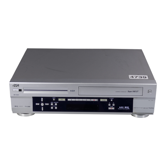
HDD & S-VHS VIDEO RECORDER
SPECIFICATIONS
GENERAL
Power requirement
Power consumption
Power on
Power off
Temperature
Operating
Storage
Operating position
Dimensions (WxHxD) : 435 mm x 124 mm x 385 mm
Weight
Input/Output
HDD DECK VIDEO/AUDIO
Video format
Audio format
Maximum recording time (approx.)
(SP)
(LP)
(EP)
(SEP)
VHS DECK VIDEO/AUDIO
Signal system
Recording system
Format
Signal-to-noise ratio
Horizontal resolution
(SP/LP)
S40894
(EP)
Printed in Japan
HM-HDS1EK/EU
1
2
1
2
3
4
5
6
3
7
8
9
4
<
0
>
ñ
+
(The specifications shown pertain specifically to the model HM-HDS1EU)
Frequency range
: AC 220 V – 240 V ` , 50 Hz/60 Hz
Maximum recording time
(SP)
: 41 W
(LP)
: 16 W
(EP)
: 5°C to 40°C
TUNER/TIMER
: –20°C to 60°C
: Horizontal only
TV channel storage capacity
: 7.3 kg
Tuning system
: 21-pin SCART connectors:
Channel coverage
IN/OUT x 1, IN/DECODER x 1
RCA connectors:
VIDEO IN x 1, AUDIO IN x 1,
AUDIO OUT x 1
Aerial output
S-Video connectors: IN x 1, OUT x 1
Memory backup time
: MPEG2 (VBR)
ACCESSORIES
: MPEG1 Layer2
Provided accessories
: 14 hours
: 20 hours
: 28 hours
: 40 hours
: PAL-type colour signal and CCIR monochrome
Specifications shown are for SP mode unless otherwise specified.
signal, 625 lines 50 fields
E. & O.E. Design and specifications subject to change without notice.
: DA4 (Double Azimuth) head helical scan system
: S-VHS/VHS PAL standard
: 45 dB
: 250 lines (VHS)
400 lines (S-VHS)
: 220 lines (VHS)
350 lines (S-VHS)
This service manual is printed on 100% recycled paper.
COPYRIGHT © 2001 VICTOR COMPANY OF JAPAN, LTD.
F - 1
: 70 Hz to 10,000 Hz (Normal audio)
20 Hz to 20,000 Hz (Hi-Fi audio)
: 240 min. with E-240 video cassette
: 480 min. with E-240 video cassette
: 720 min. with E-240 video cassette
: 99 positions (+AUX position)
: Frequency synthesized tuner
: VHF 47 MHz – 89 MHz/
104 MHz – 300 MHz/
302 MHz – 470 MHz
UHF 470 MHz – 862 MHz
: UHF channels 22 – 69 (Adjustable)
: Approx. 60 min.
: RF cable,
21-pin SCART cable,
Satellite Controller,
Infrared remote control unit,
"R6" battery x 2
No. 82887
July 2001
Advertisement
Table of Contents

Related Manuals for JVC HM-HDS1EK


Summary of Contents for JVC HM-HDS1EK
- Page 1 SERVICE MANUAL HDD & S-VHS VIDEO RECORDER HM-HDS1EK/EU < > ñ F - 1 SPECIFICATIONS (The specifications shown pertain specifically to the model HM-HDS1EU) GENERAL Frequency range : 70 Hz to 10,000 Hz (Normal audio) 20 Hz to 20,000 Hz (Hi-Fi audio) Power requirement : AC 220 V –...
- Page 2 Hard Disk Drive (HDD) 1. Hard Disk Drive (HDD) Handling Precautions The HDD is a precision device for use in reading and writing a large amount of data on or from a disk rotating at a high speed. If it is not handled carefully, either abnormal operation may result or it may not be possible to read data.
- Page 3 2. In Case of an HDD Failure When a HDD/VHS DUAL RECORDER AC cord is plugged into a power outlet, the boot loader is read from the IC8204 (8M FLASH ROM), which activates the HDD and reads the system files in the HDD before getting ready for operation.
-
Page 4: Table Of Contents
DIGITAL BOARD ASSEMBLY <50> ............5-22 3.1.5 EVR Adjustment ................3-1 LOADING MOTOR BOARD ASSEMBLY <55> ........5-27 LED BOARD ASSEMBLY <90> .............. 5-27 The following table lists the differing points between Models ( HM-HDS1EK and HM-HDS1EU) in this series. HM-HDS1EK HM-HDS1EU VIDEO SYSTEM... -
Page 5: Important Safety Precautions
Important Safety Precautions Prior to shipment from the factory, JVC products are strictly inspected to conform with the recognized product safety and electrical codes of the countries in which they are to be sold. However, in order to maintain such compliance, it is equally important to implement the following precautions when a set is being serviced. - Page 6 • Safety Check after Servicing Examine the area surrounding the repaired location for damage or deterioration. Observe that screws, parts and wires have been returned to original positions, Afterwards, perform the following tests and confirm the specified values in order to verify compliance with safety standards.
-
Page 7: Disassembly
SECTION 1 DISASSEMBLY 1.1 HOW TO REMOVE THE MAJOR PARTS 1.3 DISCONNECTION OF CONNECTORS (WIRES) 1.1.1 Introduction This set is a double-deck video recorder integrating a HDD (Hard Disk Drive) and a VHS deck. Its internal structure is di- vided into three sections that include the power supply, VHS CONNECTOR and HDD sections. -
Page 8: How To Remove The Major Parts
1.5 HOW TO REMOVE THE MAJOR PARTS <COM section> 1.5.1 Disassembly flow chart This flowchart shows the disassembly procedure for the ex- terior parts and electrical parts. Top cover ( S2 ) Basically, reverse this procedure when assembling them. ( S2 ) ( S1 ) Top cover, Bracket ( S1 ) - Page 9 CN5325 CN5321 CN5322 Eject SW Foil side CN5326 board assembly <Note 1> Foil side CN5323 Jack <Note 1> board assembly LED/SW board assembly ( S4 ) LED board assembly ( S4 ) Display board assembly ( S4 ) ( S4 ) ( S4 ) ( S4 ) ( S4 )
-
Page 10: How To Remove The Major Parts
1.6 HOW TO REMOVE THE MAJOR PARTS <VHS section> Procedures for Lowering the Cassette holder assembly As the mechanism of this unit is integrated with the Housing 1.6.1 Disassembly flow chart assembly, the holder must be lowered and the two screws un- This flowchart shows the disassembly procedure for the ex- screwed when removing the Mechanism assembly. - Page 11 Note: When installing the Mechanism assembly, secure (S3) the screws (S8) in the order of a , b . Foil side Foil side <Note 2> <Note 2> (S8) WR11 (S3) (S5) (S3) Foil side CN3014 <Note 4> <Note 2> (S3) <Note 4>...
-
Page 12: Hard Disk Drive (Hdd) Handling Precautions
Hard Disk Drive (HDD) Handling Precautions (S5) The HDD is a precision device for use in reading and writing (S5) a large amount of data on or from a disk rotating at a high (S5) speed. If it is not handled carefully, either abnormal opera- (S5) tion may result or it may not be possible to read data. -
Page 13: Service Positions
1.8 SERVICE POSITIONS < Installation > The servicing locations for use in troubleshooting or servic- (1) Stand up the bottom chassis assembly so that the Regu- ing of the set are provided separately for the VHS and HDD. lator side is in the lower position. (2) Connect the PATCH CORD to the three FPCs then con- SERVICE POSITIONS <VHS SIDE>... -
Page 14: Service Position
1.8.2 Service position <HDD SIDE> (1) Remove the exterior parts (Top cover and front panel as- sembly). (2) Remove the hard disk drive(HDD) together with the frame. PATCH CORD PTU94017B (3) Remove the digital board assembly together with the wires CN8001 attached to it, and place the assembly upside down on CN8901... -
Page 15: Mechanism Service Mode
1.9 MECHANISM SERVICE MODE This model has a unique function to enter the mechanism (5) With lock levers A B on the left and right of the Cassette into every operation mode without loading of any cassette holder assembly pulled toward the front, slide the holder tape. -
Page 16: Top View
1.10 CONNECTION TOP VIEW Treat wire so as not to come to the FAN motor. CN512 FAN motor CN703 Supporting tape side CN5325 CN7506 CN5322 Foil side Foil side Make a crease. CN2601 CN7508 Make a crease. Foil side Treat the wire according to the Supporting Foil side... -
Page 17: Connection
Type Connection Fig. Pin No. (FPC/ Symbol ←→ Connected point Connected point WIRE) ←→ MAIN CN7507 JACK CN7002 ←→ MAIN CN3011 DISPLAY CN7001 ←→ REGULATOR CN5301 SW REG CN5201 ←→ REGULATOR CN5322 MAIN CN7508 ←→ REGULATOR CN5321 MAIN CN7509 ←→ REGULATOR CN5325 FAN MOTOR... -
Page 18: Emergency Display Function
1.11.1 Displaying the emergency information 1.11 EMERGENCY DISPLAY FUNCTION (1) Transmit the code “59” from the Jig RCU. This unit has a function for storing the history of the past two The FDP shows the emergency content in the form of emergencies (EMG) and displaying them on each FDP. -
Page 19: Emergency Content Description
1.11.3 Emergency content description Note: Emergency contents “E08/E09” are for the model with Dynamic Drum (DD). CONTENT CAUSE E01: Loading EMG When the mechanism mode cannot be changed to an- 1 The mechanism is locked in the middle of mode transition. 2 The mechanism is locked at the loading end due to the encoder position other mode even when the loading motor has rotated for more than 4 seconds in the loading direction, [E:01]... -
Page 20: Emergency Detail Information 1
1.11.4 Emergency detail information 1 : Mechanism Operation Mode [Table of MN] The status (electrical operation mode) of the VCR and the sta- tus (mechanism operation mode/sensor information) of the Display Mechanism Operation Mode Command standby (Status without executing command) mechanism in the latest emergency can be confirmed based on POWER OFF by EMG occurrence the figure in EMG detail information 1 . -
Page 21: Emergency Detail Information 2
1.11.5 Emergency detail information 2 : Mechanism Sensor Information 3 – [Common table of MN and HD] The type of the cassette tape and the cassette tape winding po- sition can be confirmed based on the figure in EMG detail infor- Mechanism Sensor Information Display S-VHS SW... -
Page 22: Mechanism Adjustment (Vhs)
SECTION 2 MECHANISM ADJUSTMENT 2.1 Before starting repair and adjustment 2.1.1 Precautions (1) Unplug the power cord plug of the VCR before using your Loading motor soldering iron. (2) Take care not to cause any damage to the conductor wires when plugging and unplugging the connectors. (3) Do not randomly handle the parts without identifying where the trouble is. -
Page 23: Jigs And Tools Required For Adjustment
2. In case of mechanical failure 2.1.4 Jigs and tools required for adjustment If you cannot remove the cassette tape which is loaded be- Roller driver A/C head positioning tool Torque gauge cause of any mechanical failure, manually remove it by tak- PTU94002 PTU94010 PUJ48075-2... -
Page 24: Maintenance And Inspection
2.1.5 Maintenance and inspection 1. Location of major mechanical parts In this chapter, the two mechanism speeds are described by comparing the speeds of the standard type and the high-speed FF/REW type. It is possible to distinguish between these two types of mechanism by the diameters of their capstan pulleys. The capstan pulley diameter for the standard type is approx. - Page 25 4. Suggested servicing schedule for main components The following table indicates the suggested period for such Guide rail Roller cam assembly service measures as cleaning,lubrication and replacement. In practice, the indicated periods will vary widely according to environmental and usage conditions.However, the indi- cated components should be inspected when a set is brought for service and the maintenance work performed if neces- sary.
- Page 26 Symbols and numbers R4 R1 T9 T12 T11 B15 B12 B14 B13 B17 B21 B7 B8 B5 B4 B11 T14 T15 T13 T22 T24 T18 B19 Removal parts (Reference items) Replacement parts 2.2.3 Guide rail 2.2.3 Roller cam assembly 2.2.3 Cassette housing bracket 2.2.3 Opener guide 2.2.3 Door opener 2.2.3 Relay gear...
-
Page 27: Replacement Of Major Parts
2.2 Replacement of major parts 2.2.3 Cassette holder assembly 1. How to remove 2.2.1 Before starting disassembling (Phase matching (1) Remove the guide rail and roller cam assembly. (See between mechanical parts) Fig.2-2-3a.) The mechanism of this unit is closely linked with the rotary (3 lugs on the guide rail and one lug on the roller cam encoder and system controller circuits. - Page 28 (5) While holding the left side of the cassette holder, lift the 2. How to install (Phase matching) cassette holder assembly so that the three legs on the (1) Insert the section (A) of the drive arm into the section (B) left side are all released.
-
Page 29: Pinch Roller Arm Assembly
2.2.6 A/C head Notches Guide hole Notch 1. How to remove Relay gear (1) Remove the two screws (A) and remove the A/C head together with the head base. (2) When replacing only the A/C head, remove the three screws (B) while controlling the compression spring. Head base Screws(A) Drive gear... -
Page 30: Capstan Motor
2. How to install (Centering the mounting position) Loading motor board assembly When the capstan motor has once been removed and then reinstalled out of the initial correct position in the rotational Loading motor direction, the capstan motor current may be unstable during Lugs operation in high or low temperatures. -
Page 31: Rotary Encoder
2.2.10 Rotary encoder 2.2.12 Change lever assembly, direct gear, clutch gear and coupling gear 1. How to remove (1) Remove the screw (A) and remove the rotary encoder 1. How to remove (1) Release the two lugs of the rotary encoder guide in the by pulling it up. -
Page 32: Link Lever
2.2.13 Link lever 2.2.14 Cassette gear, control cam and worm gear 1. How to remove 1. How to remove (1) Remove the two slit washers. (1) Remove the control cam by lifting it. (2) Remove the link lever by lifting it from the shaft retained (2) Open the two lugs of the cassette gear outward and pull by the slit washers. -
Page 33: Loading Arm Gear (Supply Or Take-Up Side) And Loading Arm Gear Shaft
(3) Install the control plate so that the section A of the load- (3) Turn the loading arm gear (take-up side) clockwise so ing arm gear shaft fits into the hole (A) of the control plate, that the notch of the loading arm gear (take-up side) is the section B of the control plate guide into the hole (B), in alignment with the projection of the loading arm gear and the control plate comes under the section C of the... -
Page 34: Take-Up Lever, Take-Up Head And Control Plate Guide
2.2.17 Take-up lever, take-up head and control plate guide (1) Remove the spring of the take-up lever from the main deck. Spring (2) Remove the lug (A) of the take-up lever from the main Sub brake assembly deck and pull out the take-up lever and the take-up head Lug(A) (take-up side) together. -
Page 35: Tension Brake Assembly, Reel Disk (Supply Side) And Tension Arm Assembly
2.2.21 Tension brake assembly, reel disk (supply side) 2.2.23 Stator assembly and tension arm assembly (1) Remove the flat cable. 1. How to remove (2) Remove the two screws (A), (B) and remove the lug wire. (1) Remove the three lugs of the tension brake assembly (3) Remove the stator assembly by lifting in the arrow-indi- from the main deck and pull them off. -
Page 36: Upper Drum Assembly
2.2.25 Upper drum assembly Notes: • To replace the upper drum assembly only may not be possible with some models. For upper drum assem- bly replacement, refer to the parts list. (When the parts number of the upper drum assembly is not listed on Lower drum assembly the parts list, then this cannot be replaced.) •... -
Page 37: Compatibility Adjustment
2.3 Compatibility adjustment (7) Unload the cassette tape once, play back the alignment tape (A1) again and confirm the V.PB FM waveform. Notes: (8) After adjustment, confirm that the tape wrinkling does not • Although compatibility adjustment is very important, occur at the roller upper or lower limits. -
Page 38: Height And Tilt Of The A/C Head
(4) Adjust the AUDIO OUT waveform and Control pulse waveform by turning the screws (1), (2) and (3) little by little until both waveforms reach maximum. The screw (1) and (3) are for adjustment of tilt and the screw (2) for azi- muth. -
Page 39: Standard Tracking Preset
[Perform adjustment steps (7) to (10) only for 2 Head (4) Set the VCR to the Auto adjust mode by transmitting the models equipped with LP mode.] code (F) twice from the Jig RCU. When the VCR enters the stop mode, the adjustment is completed. (7) Then play back the alignment tape (A2). - Page 40 Mechanism Timing Chart EJECT CASS- Mechanism mode CASS-INS FF/REW STOP SLOW/STILL PLAY Control plate mark HIGH C CH HIGH Rotary encoder B CH HIGH A CH Control cam angle 264. 318. 412. Rotary encoder 114. 150. 167. 178. 207. 218. 240.
-
Page 41: Electrical Adjustment (Vhs)
SECTION 3 ELECTRICAL ADJUSTMENT 3.1 PRECAUTION Jig RCU The following adjustment procedures are not only necessary [Data transmitting method] Depress the “ ” ( 3 ) button after replacement of consumable mechanical parts or board after the data code is set. assemblies, but are also provided as references to be re- CUSTOM CODE ferred to when servicing the electrical circuitry. -
Page 42: Servo Circuit
(1) Record the signal (A2) in the mode (B1), and play back the recorded signal. (2) Press the channel buttons (+, –) simultaneously to enter the manual tracking mode. This also brings tracking to the center (centre). (3) Set the VCR to the FWD slow (+1/6×) mode. (4) Transmit the code (F) from the Jig RCU to adjust so that Fig. -
Page 43: Ee Y Level
3.3.2 EE Y level (7) Release the EVR mode of the VCR by transmitting the code (F1) from the Jig RCU again. (When the EVR mode • Signal (A1) Ext. input is released, the adjusted data is memorized.) • (A2) Color (colour) bar signal [PAL] (8) Repeat steps (2) to (7) in the mode (B2). -
Page 44: Video Eq (Frequency Response)
(9) Adjust with the channel buttons (+, –) on the VCR (or on (7) Release the EVR mode of the VCR by transmitting the code (F1) from the Jig RCU again. (When the EVR mode the remote controller) so that the higher level channel be- is released, the adjusted data is memorized.) comes the specified value (G) of the note "B"... -
Page 45: Hdd Pb Y Level
3.4.2 HDD PB Y level 3.5 AUDIO CIRCUIT • Notes: Signal (A1) Ext. input • (A2) Color(colour) bar signal[PAL] • This adjustment should be done after the “REC color • (colour) level adjustment” for the video circuit has Mode been completed. •... -
Page 46: Syscon Circuit [Hm-Hds1Eu]
3.6 SYSCON CIRCUIT [HM-HDS1EU] Note: • When perform this adjustment, remove the Mechanism assembly. 3.6.1 Timer clock Signal • No signal Mode • EE Equipment • Frequency counter Measuring point (D1) • IC3001 pin 61 Short point (D2) • IC3001 pin 24 (D3) •... -
Page 47: Charts And Diagrams
SECTION 4 CHARTS AND DIAGRAMS 4) Indication on schematic diagram NOTES OF SCHEMATIC DIAGRAM Voltage Indications for REC and PB mode on the sche- matic diagram are as shown below. Safety precautions The Components identified by the symbol critical for safety. For continued safety, replace safety critical components only with manufacturer's recom- REC mode mended parts. -
Page 48: Circuit Board Notes
6. Signal path Symbols CIRCUIT BOARD NOTES The arrows indicate the signal path as follows. 1. Foil and Component sides 1) Foil side (B side) : Playback signal path Parts on the foil side seen from foil face (pattern face) are indicated. -
Page 49: Board Interconnections
OPEN J7107 J7108 J7109 J7104 J7105 J7106 DECODER_IN DET_IN/OUT REAR_IN REAR_1_OUT REAR_2_OUT V_IN A_IN(R) A_IN(L) OUT(M-N) OUT(M) AFC_IN BIT_IN BIT_OUT V_IN A_IN(R) A_IN(L) V_OUT A_OUT(R) A_OUT(L) V_OUT A_OUT(R) A_OUT(L) BOARD INTERCONNECTIONS MS MODEL ONLY TERMINAL J7101 J7102 J7103 S-OUT REAR_S1_OUT REAR_S2_OUT (Page 4-23) S/P CONVERTER... -
Page 50: Switching Regulator And Regulator Schematic Diagrams
SWITCHING REGULATOR AND REGULATOR SCHEMATIC DIAGRAMS Note : The Parts Number , value and rated voltage etc. in the Schematic Diagram are for references only. When replacing the parts , refer to the Parts List. DANGEROUS VOLTAGE CN5321 BS_SW5V CP5324 ICP-N20 REGULATOR AL17V... -
Page 51: Video/Audio Schematic Diagram
The Parts Number , value and rated voltage etc. in the Schematic Diagram are for references only. Note : VIDEO/AUDIO SCHEMATIC DIAGRAM When replacing the parts , refer to the Parts List. MAIN (VIDEO/AUDIO) CONNECTION AUDIO I/O R2003 0Ω FMA_OUT[L] R2206 0Ω... -
Page 52: System Control Schematic Diagram
The Parts Number , value and rated voltage etc. in the Schematic Diagram are for references only. Note : SYSTEM CONTROL SCHEMATIC DIAGRAM When replacing the parts , refer to the Parts List. MAIN (SYSCON) I2C_CLK_A/V I2C_DATA_A/V V.P_CTL P.SAVE CONNECTION SLOW_P/CNR_CTL P.MUTE[L] PAUSE... - Page 53 : Used #DIFFERENCE TABLE X : Not used HR-DVS2 HM-HDS1 The Parts Number , value and rated voltage etc. in the Schematic Diagram are for references only. Note : /SR-VS20 ITEM EU/EK EU/EK When replacing the parts , refer to the Parts List. JOG/S B3003 D3011...
-
Page 54: Video I/O Switch Schematic Diagram
VIDEO I/O SWITCH SCHEMATIC DIAGRAM The Parts Number , value and rated voltage etc. in the Schematic Diagram are for references only. Note : When replacing the parts , refer to the Parts List. 0 3 VIDEO I/O SW B701 C718 C720 IC703... -
Page 55: Audio I/O Schematic Diagram
AUDIO I/O SCHEMATIC DIAGRAM The Parts Number , value and rated voltage etc. in the Schematic Diagram are for references only. Note : When replacing the parts , refer to the Parts List. MAIN (AUDIO I/O) SYSCON DV_A.MUTE[H] IN_SEL_B IN_SEL_A B2607 D_R2/D_R1Y/D_FV C2607... -
Page 56: Connection Schematic Diagram
CONNECTION SCHEMATIC DIAGRAM The Parts Number , value and rated voltage etc. in the Schematic Diagram are for references only. Note : When replacing the parts , refer to the Parts List. TO S_SUB CN511 TO TERMINAL TO TERMINAL TO TERMINAL TO TERMINAL TO 3D DIGITAL/2M CN1401 CN7103... -
Page 57: Tuner Schematic Diagram
The Parts Number , value and rated voltage etc. in the Schematic Diagram are for references only. Note : TUNER SCHEMATIC DIAGRAM When replacing the parts , refer to the Parts List. 3 MAIN (TUNER) Used # DIFFERENCE TABLE TU6001 ANT IN ANT OUT Not Used... -
Page 58: Digital/2M Schematic Diagram
Note : The Parts Number , value and rated voltage etc. in the Schematic Diagram are for references only. 3D DIGITAL/2M SCHEMATIC DIAGRAM When replacing the parts , refer to the Parts List. 0 5 3D DIGITAL/2M R1447 C1459 R1448 C1460 R1449 C1461... -
Page 59: Terminal Schematic Diagram
4.10 TERMINAL SCHEMATIC DIAGRAM The Parts Number , value and rated voltage etc. in the Schematic Diagram are for references only. Note : When replacing the parts , refer to the Parts List. TERMINAL C7104 C7108 C7115 0.01 0.01 C7109 OPEN OPEN L7101... -
Page 60: Demodulator Schematic Diagram
4.11 DEMODULATOR SCHEMATIC DIAGRAM The Parts Number , value and rated voltage etc. in the Schematic Diagram are for references only. Note : When replacing the parts , refer to the Parts List. 1 4 DEMOD # DIFFERENCE TABLE Used Not used FRANCE MS BASIC... -
Page 61: S-Sub Schematic Diagram
The Parts Number , value and rated voltage etc. in the Schematic Diagram are for references only. Note : 4.12 S-SUB SCHEMATIC DIAGRAM When replacing the parts , refer to the Parts List. TO MAIN (CONNECTION) 1 5 S-SUB CN502 CN511 TO MAIN (P/S CONV) EE[L]... -
Page 62: On Screen Schematic Diagram
4.13 ON SCREEN SCHEMATIC DIAGRAM The Parts Number , value and rated voltage etc. in the Schematic Diagram are for references only. Note : When replacing the parts , refer to the Parts List. 1 7 ON SCREEN B859 OPEN B856 OPEN R858... -
Page 63: Eject Sw, Display, Jack, Led/Sw And Led Schematic Diagrams
4.14 EJECT SW, DISPLAY, JACK, LED/SW AND LED SCHEMATIC DIAGRAMS The Parts Number , value and rated voltage etc. in the Schematic Diagram are for references only. Note : OPEN When replacing the parts , refer to the Parts List. 8 5 JOG DISPLAY D7006... -
Page 64: Digital P.sup Schematic Diagram
4.15 DIGITAL P.SUP SCHEMATIC DIAGRAM The Parts Number , value and rated voltage etc. in the Schematic Diagram are for references only. Note : When replacing the parts , refer to the Parts List. DIGITAL(P.SUP) TO AUDIO AD/DA AUDIO[-] TO REGULATOR CN5323 D3.3V CN8901... -
Page 65: Digital Video Schematic Diagram
4.16 DIGITAL VIDEO SCHEMATIC DIAGRAM The Parts Number , value and rated voltage etc. in the Schematic Diagram are for references only. Note : When replacing the parts , refer to the Parts List. 5 0 DIGITAL(VIDEO AD/DA) 2SA1774/RS/-X 2SC4617/RS/-X R8603 R8606 R8679... -
Page 66: Digital Audio Schematic Diagram
4.17 DIGITAL AUDIO SCHEMATIC DIAGRAM The Parts Number , value and rated voltage etc. in the Schematic Diagram are for references only. Note : When replacing the parts , refer to the Parts List. DIGITAL(AUDIO AD/DA) L8801 TO P.SUP NQR0339-001X AUDIO[-] D3.3V L8802... -
Page 67: Digital Mpeg Dec Schematic Diagram
4.18 DIGITAL MPEG DEC SCHEMATIC DIAGRAM OPEM The Parts Number , value and rated voltage etc. in the Schematic Diagram are for references only. Note : When replacing the parts , refer to the Parts List. DIGITAL(MPEG DEC.) TL8209 TL8208 TL8207 SDRAM FRASH... -
Page 68: Digital Mpeg Enc Schematic Diagram
4.19 DIGITAL MPEG ENC SCHEMATIC DIAGRAM The Parts Number , value and rated voltage etc. in the Schematic Diagram are for references only. Note : When replacing the parts , refer to the Parts List. DIGITAL(MPEG ENC.) VIDEO AD/DA IC8402 C8440 KM416S1120DT-G8 ASIC IF... -
Page 69: Digital Asic If Schematic Diagram
The Parts Number , value and rated voltage etc. in the Schematic Diagram are for references only. Note : 4.20 DIGITAL ASIC IF SCHEMATIC DIAGRAM When replacing the parts , refer to the Parts List. DIGITAL(ASIC IF) R8031 R8032 OPEN R8029 OPEN D8001... -
Page 70: Digital Sub Schematic Diagram
4.29 DIGITAL SUB SCHEMATIC DIAGRAM There are currently two types of Digital board assemblies in used, these are the LPA10121-04B and the LPA10121-04C. These two boards have different Schematic Diagrams and Parts Lists. Be sure to check the board number. The Parts Number , value and rated voltage etc. -
Page 71: Remote Control Schematic Diagram
4.31 REMOTE CONTROL SCHEMATIC DIAGRAM ( LP20873-009# ) KEY No. KEY NAME TV/CABLE/SAT SVHS ( POWER ) VCC ( 3V ) LCD PROG AUDIO/ - - : - - TV/VCR 80 79 78 77 76 75 74 73 72 71 70 69 68 67 66 65 64 63 62 61 NAVIGATION P60/KR0 ( TRANS ) -
Page 72: Waveforms
4.32 WAVEFORMS < VIDEO > TP106 TP111 IC1-27 PB FM D.FF IC1-105 WF12 CN512-6 WF13 CN512-12 WF14 IC1-30 IC1-1 CN512-14 PB 2.3 Vp-p PB 0.88 Vp-p REC/PB 4.3 Vp-p REC 2.0 Vp-p REC/PB 2.2 Vp-p REC 0.7 Vp-p PB 0.52 Vp-p PB 0.3 Vp-p REC 1.0 Vp-p 0.1 V/10 msec/DIV... -
Page 73: Voltage Charts
4.33 VOLTAGE CHARTS <SW REGULATOR> <VIDEO AD/DA> MODE MODE MODE MODE MODE MODE MODE MODE MODE MODE MODE MODE MODE MODE MODE MODE PLAY PLAY PLAY PLAY PLAY PLAY PLAY PLAY PLAY PLAY PLAY PLAY PLAY PLAY PLAY PLAY PIN NO. PIN NO. -
Page 74: Cpu Pin Function
4.34 CPU PIN FUNCTION MODE MODE MODE MODE MODE MODE MODE MODE PLAY PLAY PLAY PLAY PLAY PLAY PLAY PLAY PIN NO. PIN NO. PIN NO. PIN NO. PIN NO. PIN NO. PIN NO. PIN NO. <SYSCON IC3001> PIN NO. LABEL IN/OUT FUNCTION... -
Page 75: System Control Block Diagram (Vhs)
4.35 SYSTEM CONTROL BLOCK DIAGRAM (VHS) MAIN ( SYSCON ) IC3001 ( SYSTEM CONTROL MICRO PROCESSOR ) C3025 CN3003 Timer clock VIDEO I/O SW CAP_REV ( L ) CAP REV ( L ) X3001 CN704 TIMER CLOCK S.DATA_FRSYS (32KHz) S.CLK CAP_CTL_V CAPPWM ONLY USED... -
Page 76: Audio Block Diagram
4.36 AUDIO BLOCK DIAGRAM (VHS) MAIN ( VIDEO/AUDIO, AUDIO I/O, CONNECTION ) TUNER DEMOD(R) DEMOD(L) TU_AUDIO IC2605 IC2606 A.MUTE(H) ( VIDEO & AUDIO SIGNAL PROCESSOR ) USED A.FF FRONT IN CN7002 CN7507 I2C_DATA_A/V FRONT_A(R) J7003 I2C_CLK_A/V FRONT_A(L) R_IN A.ENV/ND(L) H.REC_ST(H) A.MUTE (H) PAL_PB(H) J7004... -
Page 77: Video Block Diagram(Vhs)
4.37 VIDEO BLOCK DIAGRAM (VHS) ( Y/C SEP & MIX ) IC1401 DIGITAL/2M DFFI SDATA SCLK COUT com/CNR Q1402 COMB YOUT CN1401 D.FF Y COMB Q1406 V.REF I2C DATA A/V I2C CLK A/V C FROM DIGI Q1404 Y FROM DIGI Q1408 Q1414 EE(L) - Page 78 TP106 MAIN (VIDEO, VIDEO I/O SW, CONNECTION) PB FM 2Fsc TUNER TUNER_VIDEO & EQ ( VIDEO & AUDIO V.PULSE SIGNAL PROCESSOR ) I2C_DATA_A/V SYSCON I2C_CLK_A/V D_VHS(H)/D_SEPA(H) C.SYNC/V.REF TP111 D.FF X-tal CR Det TP701 SYNC VCO/OSC 2fsc VCO 2fsc CLAMP Clamp D AGC fH LOCK CTL D.FF...
-
Page 79: Video/Audio Block Diagram (Hdd)
4.38 VIDEO/AUDIO BLOCK DIAGRAM (HDD) DIGITAL (VIDEO AD/DA, AUDIO AD/DA, MPEG DEC, MPEG ENC, ASIC IF ) IC8001 ASIC_IF HARD DISK DRIVER IC8206 IC8207 IC8204 IC8201 MPEG DEC D0 - D7 136 - 139, 141 - 144, 146 136, 137 VHS MAIN Q0 - Q7 148 - 153, 155, 157, 158... -
Page 80: Parts List
SECTION 5 PARTS LIST SAFETY PRECAUTION Parts identified by the symbol are critical for safety. Replace only with specified part numbers. PACKING AND ACCESSORY ASSEMBLY <M1> The instruction manual to be provided with this product will differ according to the destination. SPEC OF BARCODE 316 (HDS1EU) 317 (HDS1EK) -
Page 81: Final Assembly
FINAL ASSEMBLY <M2> BEWARE OF BOGUS PARTS Parts that do not meet specifications may cause trouble in regard to safety and performance. We recommend that genuine JVC parts be used. 505F 505E RATING LABEL (SERIAL) LEBEL (PATENT) 3D DIGITAL/2M BOARD ASSY <05>... - Page 82 REF No. PART No. PART NAME, DESCRIPTION REF No. PART No. PART NAME, DESCRIPTION - - - - - - - - - - - - - - - - - - - - - - - - - - - - - - - - - - - - - - - - - - - - - - - - - - - - - - - - - - - - - - - - - - - - - - - - - - - - - - - - - - - - - - - - - - - - - - - - - - - - - - - - - - - - - - - - - - - - - - - - - - - - - - - - - -...
-
Page 83: Mechanism Assembly
MECHANISM ASSEMBLY <M4> A/C HEAD BOARD ASSY <12> LOADING MOTOR BOARD ASSY <55> Classifi- Symbol in Part No. NOTE:This section indicates that the grease and oil are to be cation drawing applied on locations marked with AA and BB. Grease KYODO-SH-P During checking and servicing, check if grease has been COSMO-HV56... - Page 84 REF No. PART No. PART NAME, DESCRIPTION REF No. PART No. PART NAME, DESCRIPTION - - - - - - - - - - - - - - - - - - - - - - - - - - - - - - - - - - - - - - - - - - - - - - - - - - - - - - - - - - - - - - - - - - - - - - - - - - - - - - - - - - - - - - - - - - - - - - - - - - - - - - - - - - - - - - - - - - - - - - - - - - - - - - - - - -...
-
Page 85: Electrical Parts List
ELECTRICAL PARTS LIST REF No. PART No. PART NAME, DESCRIPTION REF No. PART No. PART NAME, DESCRIPTION - - - - - - - - - - - - - - - - - - - - - - - - - - - - - - - - - - - - - - - - - - - - - - - - - - - - - - - - - - - - - - - - - - - - - - - - - - - - - - - - - - - - - - - - - - - - - - - - - - - - - - - - - - - - - - - - - - - - - - - - - - - - - - - - - -... -
Page 86: Reg Board Assembly <02
REF No. PART No. PART NAME, DESCRIPTION REF No. PART No. PART NAME, DESCRIPTION - - - - - - - - - - - - - - - - - - - - - - - - - - - - - - - - - - - - - - - - - - - - - - - - - - - - - - - - - - - - - - - - - - - - - - - - - - - - - - - - - - - - - - - - - - - - - - - - - - - - - - - - - - - - - - - - - - - - - - - - - - - - - - - - - -... -
Page 87: Main Board Assembly <03
REF No. PART No. PART NAME, DESCRIPTION REF No. PART No. PART NAME, DESCRIPTION - - - - - - - - - - - - - - - - - - - - - - - - - - - - - - - - - - - - - - - - - - - - - - - - - - - - - - - - - - - - - - - - - - - - - - - - - - - - - - - - - - - - - - - - - - - - - - - - - - - - - - - - - - - - - - - - - - - - - - - - - - - - - - - - - -... - Page 88 REF No. PART No. PART NAME, DESCRIPTION REF No. PART No. PART NAME, DESCRIPTION - - - - - - - - - - - - - - - - - - - - - - - - - - - - - - - - - - - - - - - - - - - - - - - - - - - - - - - - - - - - - - - - - - - - - - - - - - - - - - - - - - - - - - - - - - - - - - - - - - - - - - - - - - - - - - - - - - - - - - - - - - - - - - - - - -...
- Page 89 REF No. PART No. PART NAME, DESCRIPTION REF No. PART No. PART NAME, DESCRIPTION - - - - - - - - - - - - - - - - - - - - - - - - - - - - - - - - - - - - - - - - - - - - - - - - - - - - - - - - - - - - - - - - - - - - - - - - - - - - - - - - - - - - - - - - - - - - - - - - - - - - - - - - - - - - - - - - - - - - - - - - - - - - - - - - - -...
- Page 90 REF No. PART No. PART NAME, DESCRIPTION REF No. PART No. PART NAME, DESCRIPTION - - - - - - - - - - - - - - - - - - - - - - - - - - - - - - - - - - - - - - - - - - - - - - - - - - - - - - - - - - - - - - - - - - - - - - - - - - - - - - - - - - - - - - - - - - - - - - - - - - - - - - - - - - - - - - - - - - - - - - - - - - - - - - - - - -...
- Page 91 REF No. PART No. PART NAME, DESCRIPTION REF No. PART No. PART NAME, DESCRIPTION - - - - - - - - - - - - - - - - - - - - - - - - - - - - - - - - - - - - - - - - - - - - - - - - - - - - - - - - - - - - - - - - - - - - - - - - - - - - - - - - - - - - - - - - - - - - - - - - - - - - - - - - - - - - - - - - - - - - - - - - - - - - - - - - - -...
- Page 92 REF No. PART No. PART NAME, DESCRIPTION REF No. PART No. PART NAME, DESCRIPTION - - - - - - - - - - - - - - - - - - - - - - - - - - - - - - - - - - - - - - - - - - - - - - - - - - - - - - - - - - - - - - - - - - - - - - - - - - - - - - - - - - - - - - - - - - - - - - - - - - - - - - - - - - - - - - - - - - - - - - - - - - - - - - - - - -...
- Page 93 REF No. PART No. PART NAME, DESCRIPTION REF No. PART No. PART NAME, DESCRIPTION - - - - - - - - - - - - - - - - - - - - - - - - - - - - - - - - - - - - - - - - - - - - - - - - - - - - - - - - - - - - - - - - - - - - - - - - - - - - - - - - - - - - - - - - - - - - - - - - - - - - - - - - - - - - - - - - - - - - - - - - - - - - - - - - - -...
-
Page 94: Digital/2M Board Assembly <05
REF No. PART No. PART NAME, DESCRIPTION REF No. PART No. PART NAME, DESCRIPTION - - - - - - - - - - - - - - - - - - - - - - - - - - - - - - - - - - - - - - - - - - - - - - - - - - - - - - - - - - - - - - - - - - - - - - - - - - - - - - - - - - - - - - - - - - - - - - - - - - - - - - - - - - - - - - - - - - - - - - - - - - - - - - - - - -... - Page 95 REF No. PART No. PART NAME, DESCRIPTION REF No. PART No. PART NAME, DESCRIPTION - - - - - - - - - - - - - - - - - - - - - - - - - - - - - - - - - - - - - - - - - - - - - - - - - - - - - - - - - - - - - - - - - - - - - - - - - - - - - - - - - - - - - - - - - - - - - - - - - - - - - - - - - - - - - - - - - - - - - - - - - - - - - - - - - -...
-
Page 96: Terminal Board Assembly <06
REF No. PART No. PART NAME, DESCRIPTION REF No. PART No. PART NAME, DESCRIPTION - - - - - - - - - - - - - - - - - - - - - - - - - - - - - - - - - - - - - - - - - - - - - - - - - - - - - - - - - - - - - - - - - - - - - - - - - - - - - - - - - - - - - - - - - - - - - - - - - - - - - - - - - - - - - - - - - - - - - - - - - - - - - - - - - -... -
Page 97: A/C Head Board Assembly <12
REF No. PART No. PART NAME, DESCRIPTION REF No. PART No. PART NAME, DESCRIPTION - - - - - - - - - - - - - - - - - - - - - - - - - - - - - - - - - - - - - - - - - - - - - - - - - - - - - - - - - - - - - - - - - - - - - - - - - - - - - - - - - - - - - - - - - - - - - - - - - - - - - - - - - - - - - - - - - - - - - - - - - - - - - - - - - -... -
Page 98: S-Sub Board Assembly <15
REF No. PART No. PART NAME, DESCRIPTION REF No. PART No. PART NAME, DESCRIPTION - - - - - - - - - - - - - - - - - - - - - - - - - - - - - - - - - - - - - - - - - - - - - - - - - - - - - - - - - - - - - - - - - - - - - - - - - - - - - - - - - - - - - - - - - - - - - - - - - - - - - - - - - - - - - - - - - - - - - - - - - - - - - - - - - -... -
Page 99: On Screen Board Assembly <17
REF No. PART No. PART NAME, DESCRIPTION REF No. PART No. PART NAME, DESCRIPTION - - - - - - - - - - - - - - - - - - - - - - - - - - - - - - - - - - - - - - - - - - - - - - - - - - - - - - - - - - - - - - - - - - - - - - - - - - - - - - - - - - - - - - - - - - - - - - - - - - - - - - - - - - - - - - - - - - - - - - - - - - - - - - - - - -... -
Page 100: Jack Board Assembly <36
REF No. PART No. PART NAME, DESCRIPTION REF No. PART No. PART NAME, DESCRIPTION - - - - - - - - - - - - - - - - - - - - - - - - - - - - - - - - - - - - - - - - - - - - - - - - - - - - - - - - - - - - - - - - - - - - - - - - - - - - - - - - - - - - - - - - - - - - - - - - - - - - - - - - - - - - - - - - - - - - - - - - - - - - - - - - - -... -
Page 101: Led/Sw Board Assembly <47
REF No. PART No. PART NAME, DESCRIPTION REF No. PART No. PART NAME, DESCRIPTION - - - - - - - - - - - - - - - - - - - - - - - - - - - - - - - - - - - - - - - - - - - - - - - - - - - - - - - - - - - - - - - - - - - - - - - - - - - - - - - - - - - - - - - - - - - - - - - - - - - - - - - - - - - - - - - - - - - - - - - - - - - - - - - - - -... - Page 102 REF No. PART No. PART NAME, DESCRIPTION REF No. PART No. PART NAME, DESCRIPTION - - - - - - - - - - - - - - - - - - - - - - - - - - - - - - - - - - - - - - - - - - - - - - - - - - - - - - - - - - - - - - - - - - - - - - - - - - - - - - - - - - - - - - - - - - - - - - - - - - - - - - - - - - - - - - - - - - - - - - - - - - - - - - - - - -...
- Page 103 REF No. PART No. PART NAME, DESCRIPTION REF No. PART No. PART NAME, DESCRIPTION - - - - - - - - - - - - - - - - - - - - - - - - - - - - - - - - - - - - - - - - - - - - - - - - - - - - - - - - - - - - - - - - - - - - - - - - - - - - - - - - - - - - - - - - - - - - - - - - - - - - - - - - - - - - - - - - - - - - - - - - - - - - - - - - - -...
- Page 104 REF No. PART No. PART NAME, DESCRIPTION REF No. PART No. PART NAME, DESCRIPTION - - - - - - - - - - - - - - - - - - - - - - - - - - - - - - - - - - - - - - - - - - - - - - - - - - - - - - - - - - - - - - - - - - - - - - - - - - - - - - - - - - - - - - - - - - - - - - - - - - - - - - - - - - - - - - - - - - - - - - - - - - - - - - - - - -...
- Page 105 REF No. PART No. PART NAME, DESCRIPTION REF No. PART No. PART NAME, DESCRIPTION - - - - - - - - - - - - - - - - - - - - - - - - - - - - - - - - - - - - - - - - - - - - - - - - - - - - - - - - - - - - - - - - - - - - - - - - - - - - - - - - - - - - - - - - - - - - - - - - - - - - - - - - - - - - - - - - - - - - - - - - - - - - - - - - - -...
-
Page 106: Loading Motor Board Assembly <55
REF No. PART No. PART NAME, DESCRIPTION REF No. PART No. PART NAME, DESCRIPTION - - - - - - - - - - - - - - - - - - - - - - - - - - - - - - - - - - - - - - - - - - - - - - - - - - - - - - - - - - - - - - - - - - - - - - - - - - - - - - - - - - - - - - - - - - - - - - - - - - - - - - - - - - - - - - - - - - - - - - - - - - - - - - - - - -...