Table of Contents
Advertisement
Advertisement
Table of Contents

Related Manuals for Bosch AVENAR FAP-425


Summary of Contents for Bosch AVENAR FAP-425
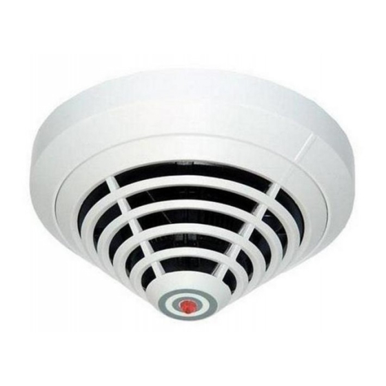
- Page 1 AVENAR detector 4000 FAP-425 / FAH-425 Operation Guide...
-
Page 3: Table Of Contents
Test Instructions for LSN improved version Fire Detectors 7.2.1 Test Instructions for All Fire Detectors With Optical Sensor 7.2.2 Test Instructions for FAP‑425‑DOTC‑R / FAP‑425‑DOT‑R / FAP‑425‑OT‑R / FAP‑425‑OT Diagnostic Data Warranty Repair Disposal Technical Data Bosch Sicherheitssysteme GmbH Operation Guide 2014.11 | 1.1 | F.01U.283.550... -
Page 4: Product Description
FAP-425-DOT-R Combined dual-optical and F.01U.279.989 Multi-sensor thermal smoke detector, automatic and manual address setting FAP-425-DOTC-R Combined dual-optical, thermal F.01U.280.451 Multi-sensor and chemical smoke detector, automatic and manual address setting 2014.11 | 1.1 | F.01U.283.550 Operation Guide Bosch Sicherheitssysteme GmbH... -
Page 5: System Overview
Depending on the specified detector class, the thermal sensor triggers the alarm status when the maximum temperature of 54 °C or 69 °C is exceeded (thermal maximum), or if the temperature rises by a defined amount within a specified time (thermal differential). Bosch Sicherheitssysteme GmbH Operation Guide 2014.11 | 1.1 | F.01U.283.550... -
Page 6: Chemical Sensor (Gas Sensor)
Individual detector identification on the fire panel in the event of an alarm. Alarm indication on the detector with a flashing red LED. – Programmable, i.e. can be adjusted to the area of operation. 2014.11 | 1.1 | F.01U.283.550 Operation Guide Bosch Sicherheitssysteme GmbH... -
Page 7: Accessories
The module detects faults according to EN 54-13 and reports errors to the fire panel. Support Plates The support plates are made from 1.8 mm thick ABS plastic and are clamped between the detector base and the ceiling. Bosch Sicherheitssysteme GmbH Operation Guide 2014.11 | 1.1 | F.01U.283.550... - Page 8 DIBt. The console is supplied with a pre-mounted MS 400 Detector Base (the detector shown is not included in the scope of delivery). 2014.11 | 1.1 | F.01U.283.550 Operation Guide Bosch Sicherheitssysteme GmbH...
-
Page 9: Remote Indicators
Unlock the snap‑fit hook by pressing on it with a flat object and lift the cap carefully Remove the connection board for easy access. Mount the base plate directly on a dry, level surface with two or four screws. Bosch Sicherheitssysteme GmbH Operation Guide 2014.11 | 1.1 | F.01U.283.550... - Page 10 For flush-mounted cables, insert the cable through the opening under the connection board. Secure the cable with a zip tie on the base plate. Wiring FAA‑420‑RI‑ROW Wire the remote indicator as shown. 2014.11 | 1.1 | F.01U.283.550 Operation Guide Bosch Sicherheitssysteme GmbH...
- Page 11 Press the cap lightly onto the base plate until the snap‑fit‑hook engages. Wiring FAA‑420‑RI‑DIN Warning! Malfunction and Damage Note the maximum permitted current supply respectively the input voltage range of the functional modes. Wire the remote indicator as shown. Bosch Sicherheitssysteme GmbH Operation Guide 2014.11 | 1.1 | F.01U.283.550...
- Page 12 0,6 – 2 mm 0,6 ‑ 0,8 mm Display medium 1 LED 2 LED Dimensions 85 x 85 x 28 mm 85 x 85 x 35 mm Weight 45 g 65 g 2014.11 | 1.1 | F.01U.283.550 Operation Guide Bosch Sicherheitssysteme GmbH...
-
Page 13: Planning
FAP-425-DO-R FAP-425-DOT-R FAP-425-DOTC-R Notice! Planning should take the anticipated total current and line resistance into account to ensure each detector has an operating voltage of at least 15 V DC. Bosch Sicherheitssysteme GmbH Operation Guide 2014.11 | 1.1 | F.01U.283.550... -
Page 14: Programming
O, T High (A2) Low* diff restaurant/meeting room = default setting Office (day mode) O, T Low (B) Medium High diff EDP room O, T High (A2) High High diff 2014.11 | 1.1 | F.01U.283.550 Operation Guide Bosch Sicherheitssysteme GmbH... -
Page 15: Fap-425-Dot-R / Fap-425-Ot-R / Fap-425-Ot
FAP‑425‑DOT‑R / FAP‑425‑OT‑R / FAP‑425‑OT Notice! The default setting of the FAP-425-DOT-R, FAP-425-OT-R and FAP-425-OT detector types in RPS is "Office (day mode)". For a description of this setting, see the below table. Bosch Sicherheitssysteme GmbH Operation Guide 2014.11 | 1.1 | F.01U.283.550... -
Page 16: Fap-425-Do-R / Fap-425-O-R / Fap-425-O
The default setting of the FAP-425-DO-R, FAP-425-O-R and FAP-425-O detector types in RPS is "Medium". For a list of possible installation locations and corresponding sensitivity settings, see the below table. 2014.11 | 1.1 | F.01U.283.550 Operation Guide Bosch Sicherheitssysteme GmbH... -
Page 17: Fah-425-T-R
To maintain the greatest possible security against false alarms, classes A1 and A1R should not be selected for room heights below 6 m, although these classes are in theory permitted. Furthermore, the expected application temperature must be taken into consideration. Bosch Sicherheitssysteme GmbH Operation Guide 2014.11 | 1.1 | F.01U.283.550... - Page 18 2 min 5 min 30 s 30 s 2 min 20 s 1 min 3 min 13 s 20 s 1 min 40 s 40 s 2 min 25 s 2014.11 | 1.1 | F.01U.283.550 Operation Guide Bosch Sicherheitssysteme GmbH...
-
Page 19: Connection
The MS 400 is the standard detector base. It has seven screw terminals. MS 400 B MS 400 standard detector base with Bosch-branding. FAA-420-SEAL For using the FAP/FAH detectors in damp environments you can supplement the MS 400 and MS 400 B detector bases with the FAA-420-SEAL damp room seal. -
Page 20: Installing The Base
Cables can be fed in and out on the same side. On the MSF 400 and MSC 420, punch out the integrated seal with a sharp tool. Do not cut with a knife. 2014.11 | 1.1 | F.01U.283.550 Operation Guide Bosch Sicherheitssysteme GmbH... -
Page 21: Connection
AVENAR detector 4000 Connection | en Ø 120 Ø 100 Connection Notice! Keep shield wire as short as possible and insulate. Bosch Sicherheitssysteme GmbH Operation Guide 2014.11 | 1.1 | F.01U.283.550... -
Page 22: Connecting The Ms 400/Ms 400 B
Connecting the FAA‑MSR 420 Maximum contact load (resistive load) of the change-over contact relay: – 62.5 VA: 0.5 A at 125 V AC – 30 W: 1 A at 30 V DC 2014.11 | 1.1 | F.01U.283.550 Operation Guide Bosch Sicherheitssysteme GmbH... -
Page 23: Detector Base Sounders
FAA-420-RI Remote indicator Detector Base Sounders Detector base sounders are used if acoustic alarm signaling is required directly at the fire source. Detector base sounders are available in four variants. Bosch Sicherheitssysteme GmbH Operation Guide 2014.11 | 1.1 | F.01U.283.550... -
Page 24: Installation Of The Detector Module
The detector module can be locked in the base (removal protection). The locking feature is activated by breaking the bolt (X) out of the base and pushing it into the corresponding guide, as shown in , page 24. 2014.11 | 1.1 | F.01U.283.550 Operation Guide Bosch Sicherheitssysteme GmbH... -
Page 25: Detector Removal
The versions without rotaries are automatically addressable only. The following settings are possible: Bosch Sicherheitssysteme GmbH Operation Guide 2014.11 | 1.1 | F.01U.283.550... - Page 26 If an LSN classic element is present, only 127 elements can be used in the loop. Please note that only loop or stub structures can be used for configurations with mixed LSN classic and LSN improved elements. 2014.11 | 1.1 | F.01U.283.550 Operation Guide Bosch Sicherheitssysteme GmbH...
-
Page 27: Order Information
Standard detector base, for surface-mount and flush- 4.998.021.535 mount cable insertion MS 400 B Standard detector base, for surface-mount and flush- F.01U.215.139 mount cable insertion, Bosch-branded FAA-420-SEAL Damp room seal for MS 400 and MS 400 B detector F.01U.215.142 bases FAA-MSR 420 Detector Base with Relay F.01U.508.658... -
Page 28: Installation Accessories
Detector Removal Tool 4.998.112.113 RTL-cap Plastic caps for the SOLO200 Detector Removal Tool 4.998.082.502 (scope of delivery = 2 pieces) FME-420-ADAP Tool Adapter for MS 420 F.01U.510.318 SOLO330 Smoke Detector Tester 4.998.112.071 2014.11 | 1.1 | F.01U.283.550 Operation Guide Bosch Sicherheitssysteme GmbH... - Page 29 Battery for SOLO461 Heat Detector Tester 4.998.147.576 FME-TESTIFIRE Multi-Stimulus Testing Tool F.01U.143.407 FME-TS3 Smoke Capsule F.01U.143.404 FME-TC3 CO-Capsule F.01U.143.405 SOLO100 Telescopic Access Pole 4.998.112.069 SOLO101 Fixed Extension Pole 4.998.112.070 SOLO610 Test Equipment Bag 4.998.112.073 Bosch Sicherheitssysteme GmbH Operation Guide 2014.11 | 1.1 | F.01U.283.550...
-
Page 30: Maintenance And Service
DIN VDE 0833; these regulations stipulate reference to the manufacturer’s instructions for maintenance intervals. – Maintenance and inspection work should be carried out regularly and by trained personnel. – BOSCH ST recommends carrying out a functional and visual inspection at least once a year. Testing Detector Type FAP-425-DO-R, FAH-425-T-R... -
Page 31: Test Instructions For Lsn Improved Version Fire Detectors
It is recommended to apply the aerosol in spurts (for example one short spurt of 1 second, 30 seconds of waiting, another short spurt). – All other detector variants: Trigger the T-piece. Bosch Sicherheitssysteme GmbH Operation Guide 2014.11 | 1.1 | F.01U.283.550... -
Page 32: Test Instructions For Fap-425-Dotc-R / Fap-425-Dot-R / Fap-425-Ot-R / Fap-425-Ot
Detector installation address, e.g. 10-03: The detector is in zone 10 and is the detector number 3. – Brief Info Additional information entered during programming. You can also enter the position of the detector here. – Type Detector type – Serial number 2014.11 | 1.1 | F.01U.283.550 Operation Guide Bosch Sicherheitssysteme GmbH... - Page 33 Medium EMC level. Consider location. >20 80…100 High EMC level. No suitable location. – Operating hours counter Operating hours starting from the initial start-up of the detector. – Error code C malfunction Bosch Sicherheitssysteme GmbH Operation Guide 2014.11 | 1.1 | F.01U.283.550...
-
Page 34: Warranty
The packaging bag used for multisensor detectors with C sensor consists of tear-resistant PE- ALU laminated film and may be disposed of with the household refuse. Defective detectors are exchanged and should be disposed of in accordance with legal regulations. 2014.11 | 1.1 | F.01U.283.550 Operation Guide Bosch Sicherheitssysteme GmbH... -
Page 35: Technical Data
> 54 °C / > 54 °C / unit > 69 °C > 69 °C > 69 °C > 69 °C Chemical Sensor range Max. monitoring area 120 m² 40m² (observe VdS guidelines) Bosch Sicherheitssysteme GmbH Operation Guide 2014.11 | 1.1 | F.01U.283.550... - Page 36 F.01U. F.01U. 280.451 279.989 279.988 280.245 280.244 280.243 The FAP-425-O and the FAP-425-OT have the same technical data as the FAP-425-O-R and FAP-425-OT-R, but are not fitted with rotary switches. 2014.11 | 1.1 | F.01U.283.550 Operation Guide Bosch Sicherheitssysteme GmbH...
- Page 38 Bosch Sicherheitssysteme GmbH Robert-Bosch-Ring 5 85630 Grasbrunn Germany www.boschsecurity.com © Bosch Sicherheitssysteme GmbH, 2014...