Bosch FPC-500-2 Operation Manual
Conventional fire panel
Hide thumbs
Also See for FPC-500-2:
- Installation manual (82 pages) ,
- Quick installation manual (172 pages)
Table of Contents
Advertisement
Quick Links
Download this manual
See also:
Installation Manual
Advertisement
Table of Contents

Related Manuals for Bosch FPC-500-2


Summary of Contents for Bosch FPC-500-2
- Page 1 Conventional Fire Panel FPC-500-2 | FPC-500-4 | FPC-500-8 Operation Guide...
-
Page 3: Table Of Contents
Shortcuts in Test Menu of Operating Level 2 Operation Operating Level 1 4.1.1 Actions 4.1.2 Menu Operating Level 2 4.2.1 Actions 4.2.2 Test/Disablements Menu 4.2.3 Menu Troubleshooting Maintenance Appendix Event Memory Test Memory Messages Index Bosch Sicherheitssysteme GmbH Operation Guide F.01U.172.982 | 5.0 | 2012.04... -
Page 4: Safety Instructions
NOTICE! If you encounter any irregularities during the operation of your fire detection system (fault messages etc.), contact your specialist immediately. F.01U.172.982 | 5.0 | 2012.04 Operation Guide Bosch Sicherheitssysteme GmbH... -
Page 5: Brief Overview
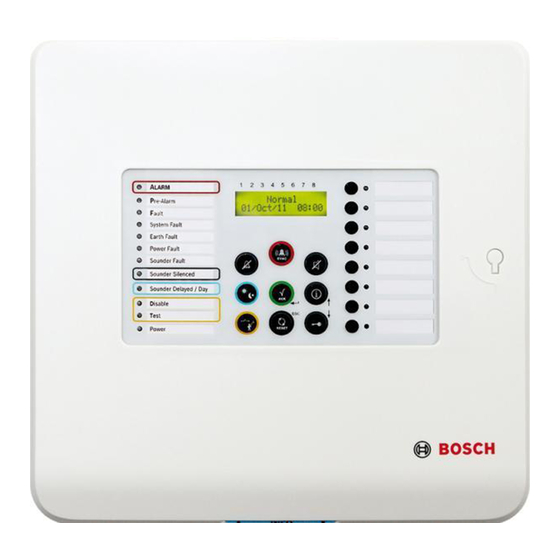
NAC Fault / Disabled Notification Appliance Silent Day Mode A CK D isable T est RESET Power LED display LCD display with zone numbers Zone keys and zone status LEDs Operating panel Bosch Sicherheitssysteme GmbH Operation Guide F.01U.172.982 | 5.0 | 2012.04... -
Page 6: System Overview
The zone is in test mode. Notification appliance Meaning fault/disabled – LED Yellow Constant Notification appliances are disabled. Yellow Flashing, 2 Hz There is a fault in the notification appliance. F.01U.172.982 | 5.0 | 2012.04 Operation Guide Bosch Sicherheitssysteme GmbH... -
Page 7: The Lcd Display
At least one zone is in test mode. The relevant zone LEDs flash at 2 Hz. Power Lit continuously in green when the system is supplied with power. The LCD Display Bosch Sicherheitssysteme GmbH Operation Guide F.01U.172.982 | 5.0 | 2012.04... - Page 8 Display of pre-alarms. Zones that have triggered a pre-alarm are flagged In addition, the total number of pre-alarms is displayed in the bottom line. The pre-alarms are then displayed one after another in order of their appearance. F.01U.172.982 | 5.0 | 2012.04 Operation Guide Bosch Sicherheitssysteme GmbH...
-
Page 9: Operating Levels
All settings for installing and programming the system. Code inputs are necessary for accessing operating levels 2 and Operating level 2 can be accessed using the optional key or an input with the appropriate configuration. Bosch Sicherheitssysteme GmbH Operation Guide F.01U.172.982 | 5.0 | 2012.04... -
Page 10: Menu Structure
System Config Date/Time Keypad Tone Language 1-A - L 2-M - Z Test menu Test MMI Test Zones Dis/Enable Zones ACK #=YES ESC=No Relays ACK #=YES ESC=No ACK #=YES ESC=No F.01U.172.982 | 5.0 | 2012.04 Operation Guide Bosch Sicherheitssysteme GmbH... -
Page 11: Shortcuts In Operating Level 1
+ C O D E Silence alarm devices (Page 20) + C O D E Display configuration (Page 25) Set date/time (Page 25) Switch key tones on/off (Page 25) Select language (Page 26) Bosch Sicherheitssysteme GmbH Operation Guide F.01U.172.982 | 5.0 | 2012.04... -
Page 12: Shortcuts In Test Menu Of Operating Level 2
Call up test menu (Page 21) + C O D E Test MMI Zones in test mode (Page 21) Disable/enable zones (Page 22) Disable/enable notification appliance Disable/enable relay (Page 23) Disable/enable all (Page 24) F.01U.172.982 | 5.0 | 2012.04 Operation Guide Bosch Sicherheitssysteme GmbH... -
Page 13: Operation
RESET Hold the RESET (ESC) key down for 2 seconds to jump to the uppermost level. Operating Level 1 4.1.1 Actions The following actions can be performed in level 1: Bosch Sicherheitssysteme GmbH Operation Guide F.01U.172.982 | 5.0 | 2012.04... - Page 14 All LEDs light up for three seconds and the buzzer sounds. Checking the zone status To check the status of a zone, press the relevant zone key (1 to 8). The LCD display shows the status of the selected zone. F.01U.172.982 | 5.0 | 2012.04 Operation Guide Bosch Sicherheitssysteme GmbH...
-
Page 15: Menu
This takes you to the Current Events submenu. Press zone key 1. The LCD shows the current fault messages. Displaying disablements Displays a list of all current disablements with the corresponding time stamps. Bosch Sicherheitssysteme GmbH Operation Guide F.01U.172.982 | 5.0 | 2012.04... - Page 16 10 steps in the corresponding direction. A description of the displayed events can be found on Page 29 ff. Displaying the test log Call up the menu; see Section Opening the menu, page 15 F.01U.172.982 | 5.0 | 2012.04 Operation Guide Bosch Sicherheitssysteme GmbH...
- Page 17 Call up the menu; see Section Opening the menu, page 15 Press the "Menu" key and then zone key 4. This takes you to the System Info submenu. Press zone key 2. The number of operation days is displayed Bosch Sicherheitssysteme GmbH Operation Guide F.01U.172.982 | 5.0 | 2012.04...
-
Page 18: Operating Level
You remain in operating level 2. If you accessed operating level 2 using the optional key, turn the key back and remove it from the lock to exit operating level F.01U.172.982 | 5.0 | 2012.04 Operation Guide Bosch Sicherheitssysteme GmbH... -
Page 19: Actions
NOTICE! As standard, the EVAC button only activates the notification appliances. CAUTION! If you have discovered a real fire, use a manual call point to trigger the alarm. Bosch Sicherheitssysteme GmbH Operation Guide F.01U.172.982 | 5.0 | 2012.04... -
Page 20: Test/Disablements Menu
A new alarm reactivates the notification appliances and relays, if programmed. 4.2.2 Test/Disablements Menu The following options are available in the test menu: – 1-Test MMI – 2-Test Zones F.01U.172.982 | 5.0 | 2012.04 Operation Guide Bosch Sicherheitssysteme GmbH... - Page 21 The "Test" LED and the LEDs for the selected zones are illuminated yellow. NOTICE! Only zones that are in a normal state can be set to test mode. Selecting a zone again removes it from test mode. Bosch Sicherheitssysteme GmbH Operation Guide F.01U.172.982 | 5.0 | 2012.04...
- Page 22 Press the "Test" key and then zone key 3. This takes you to the Dis/Enable submenu Press zone key 1. This takes you to the Zones submenu F.01U.172.982 | 5.0 | 2012.04 Operation Guide Bosch Sicherheitssysteme GmbH...
- Page 23 Press the ACK key. The notification appliances are re-enabled. Disabling relays Press the "Test" key and then zone key 3. This takes you to the Dis/Enable submenu Bosch Sicherheitssysteme GmbH Operation Guide F.01U.172.982 | 5.0 | 2012.04...
-
Page 24: Menu
In addition to the functions in level 1, the menu provides the following options: – 5-View Config – 6-System Config – 1-Date/Time – 2-Keypad Tone – 3-Language - 1- A–L - 2- M–Z F.01U.172.982 | 5.0 | 2012.04 Operation Guide Bosch Sicherheitssysteme GmbH... - Page 25 This takes you to the System Config submenu. Press zone key 2. You can now set the buzzer beep. Press the zone keys to set the buzzer beeps: – 1=On (default setting) – 2 Off Bosch Sicherheitssysteme GmbH Operation Guide F.01U.172.982 | 5.0 | 2012.04...
- Page 26 5 Român – 6 Turkçe NOTICE! If you have selected the incorrect language, you can select the language again when restarting by using a cold start (disconnect power from system). F.01U.172.982 | 5.0 | 2012.04 Operation Guide Bosch Sicherheitssysteme GmbH...
-
Page 27: Troubleshooting
"Notification appliance fault/disabled" LED flashing There is a fault with the notification appliances. Perform a system reset. If you cannot resolve the fault, please contact your specialist immediately. Bosch Sicherheitssysteme GmbH Operation Guide F.01U.172.982 | 5.0 | 2012.04... -
Page 28: Maintenance
– Please observe the appropriate requirements stipulated by the local authorities (e.g. fire service) NOTICE! Replace the batteries regularly. Please observe the appropriate requirements stipulated by the local authorities etc. F.01U.172.982 | 5.0 | 2012.04 Operation Guide Bosch Sicherheitssysteme GmbH... -
Page 29: A Appendix
3.5 A. Sys Load Normal Current consumption is back in permitted range. System Fault System fault Panel boot-up Panel has been restarted. Reset Panel Panel has been reset. Bosch Sicherheitssysteme GmbH Operation Guide F.01U.172.982 | 5.0 | 2012.04... -
Page 30: Test Memory Messages
A silenced alarm has been reactivated. Test Memory Messages Message Meaning Zone # Start Zone # set to test mode. Zone # Test Zone # successfully tested. Zone # End Zone # test mode exited. F.01U.172.982 | 5.0 | 2012.04 Operation Guide Bosch Sicherheitssysteme GmbH... -
Page 31: Index
Display test 14 Navigation Displaying Zone keys 13 Alarm counter 17 Notification appliances Event memory 16 Disable 23 Operation days 17 Pre-alarms 16 Opening Software version 17 Menu 15 Evacuation 20 Bosch Sicherheitssysteme GmbH Operation Guide F.01U.172.982 | 5.0 | 2012.04... - Page 32 Day/night mode 19 Switching off Buzzer 14 Test log Display 16 Test menu 20 Calling up 21 Test mode Zones 21 Tests Displaying 16 Zones Checking 14 Disable 22 Test mode 21 F.01U.172.982 | 5.0 | 2012.04 Operation Guide Bosch Sicherheitssysteme GmbH...
- Page 34 Bosch Sicherheitssysteme GmbH Robert-Bosch-Ring 5 85630 Grasbrunn Germany www.boschsecurity.com © Bosch Sicherheitssysteme GmbH, 2012...