Bosch FPC-500-2 Installation Manual
Conventional fire panel
Hide thumbs
Also See for FPC-500-2:
- Operation manual (34 pages) ,
- Quick installation manual (172 pages)
Table of Contents
Advertisement
Quick Links
Advertisement
Table of Contents

Related Manuals for Bosch FPC-500-2


Summary of Contents for Bosch FPC-500-2
- Page 1 Conventional Fire Panel FPC-500-2 / FPC-500-4 / FPC-500-8 Installation Guide...
-
Page 3: Table Of Contents
Setting the Time and Date System Configuration System Configuration 4.1.1 Setting the Date/Time 4.1.2 Buzzer Beep 4.1.3 EOL Elements 4.1.4 Resetting Zones 4.1.5 Aux Power 4.1.6 Faults 4.1.7 Level Code 4.1.8 Test Log Bosch Sicherheitssysteme GmbH 2014.06 | 7.0 | F.01U.172.980... - Page 4 Environmental Conditions Information as per EN 54‑4, chapter 7.1 Options with requirements as per EN 54‑2:1997/A1:2006 Appendix Brief Overview, Operating Level 1 and 2 Test menu Brief Overview, Operating Level 3 Default Settings 2014.06 | 7.0 | F.01U.172.980 Bosch Sicherheitssysteme GmbH...
- Page 5 Conventional Fire Panel Table of Contents | en Event Memory Test Memory Messages Index Bosch Sicherheitssysteme GmbH 2014.06 | 7.0 | F.01U.172.980...
-
Page 6: Safety Instructions
In line with EN 54-13 (BOSEC certificate TCC 2 - 977), each conventional line must be terminated with EOL modules for the operation of fire detection systems. The AUX power supply must also be terminated with EOL modules when using four-wire detectors. 2014.06 | 7.0 | F.01U.172.980 Bosch Sicherheitssysteme GmbH... - Page 7 Conventional Fire Panel Safety Instructions | en Notice! The fire panel has been designed for operation in closed rooms. Please note the permissible environmental conditions in the technical specifications. Bosch Sicherheitssysteme GmbH 2014.06 | 7.0 | F.01U.172.980...
-
Page 8: System Overview
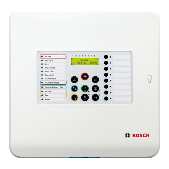
NAC Fault / Disabled Notification Appliance Silent Day Mode A CK D isable T est RESET Power LED display LCD display with zone numbers Zone keys and zone status LEDs Operating panel 2014.06 | 7.0 | F.01U.172.980 Bosch Sicherheitssysteme GmbH... - Page 9 Extensions 1 x 4 2 x 4 – Open collector (20 mA) – Relay (via OC) LCD, 2 x 16 characters ALARM RLY FAULT RLY OC (0, 4, 8) 24 V DC Bosch Sicherheitssysteme GmbH 2014.06 | 7.0 | F.01U.172.980...
- Page 10 Conventional manual call point Visual or audible notification appliances Conventional zones 1 to 8 Z1 ... Z8 (max. 2 on FPC-500-2, max. 4 on FPC-500-4) Inputs (max. 1 on FPC‑500‑2 and FPC‑500‑4, max. 2 on FPC‑500‑8) Alarm relay ALARM RLY...
- Page 11 Power supply via power supply unit with thermal fuse. – Emergency power supply using batteries, up to 7.2 Ah, reverse polarity protected. – Removable quick guide for the user on the panel. Bosch Sicherheitssysteme GmbH 2014.06 | 7.0 | F.01U.172.980...
-
Page 12: Operating Levels
– Switch between day/night mode – All actions of level 1 Level 3 – All settings for installing and programming the system. Code inputs are necessary for accessing level 2 and 3. 2014.06 | 7.0 | F.01U.172.980 Bosch Sicherheitssysteme GmbH... -
Page 13: Installation
Warning! Electrostatic discharge (ESD)! Electronic components could become damaged. Ground yourself using a wrist strap or take other suitable measures. Bosch Sicherheitssysteme GmbH 2014.06 | 7.0 | F.01U.172.980... -
Page 14: Opening The Housing
3.2.2 Opening the Housing Remove the cover of the fire panel. Loosen both screws on the underside of the housing, lift up the cover approx. 20° and remove it. 2014.06 | 7.0 | F.01U.172.980 Bosch Sicherheitssysteme GmbH... -
Page 15: Installing The Housing
6 x 50 mm 6 x 50 mm 8 x 40 mm) 8 x 40 mm) 6 x 50 mm 6 x 50 mm Bosch Sicherheitssysteme GmbH 2014.06 | 7.0 | F.01U.172.980... -
Page 16: Mains Supply
Danger! Only perform installation work when the panel has no voltage. There is a danger of an electric shock. 230 VAC 50 - 60 Hz 2014.06 | 7.0 | F.01U.172.980 Bosch Sicherheitssysteme GmbH... -
Page 17: Batteries, 24 V Emergency Power Supply
The batteries are charged again automatically. Notice! Note the polarity of the batteries. If the batteries are connected with the polarity reversed, the thermal fuse on the main board of the fire panel reacts. Bosch Sicherheitssysteme GmbH 2014.06 | 7.0 | F.01U.172.980... -
Page 18: Extensions
Note that the maximum line resistance for transistor outputs is 22.5 Ohm. The extensions are connected to the left side of the main board. Simply connect the board to the plugs. Make sure that the plug engages correctly. 2014.06 | 7.0 | F.01U.172.980 Bosch Sicherheitssysteme GmbH... -
Page 19: Wiring
External components such as zones, notification appliances, inputs, etc. are wired to screw terminals attached to the upper side of the board. Meaning FPC‑500 FPC‑500 FPC‑500 Inputs Zones Aux power supply Notification appliance Alarm and fault relay Bosch Sicherheitssysteme GmbH 2014.06 | 7.0 | F.01U.172.980... -
Page 20: Inputs
The connection terminals IN1 and IN2 are available. Notice! Note that the maximum line resistance for inputs is 22.5 ohm. Use 820 Ohm ±5% resistors for the alarm resistance (not included in scope of delivery). 2014.06 | 7.0 | F.01U.172.980 Bosch Sicherheitssysteme GmbH... -
Page 21: Zones
You can either use a 3.9 kΩ ± 1% resistor or EOL modules for an EN 54-13 (BOSEC certificate TCC 2 - 977) compliant termination. Unused zones must also be terminated with a terminal element. Mixing different terminal elements is not allowed. Bosch Sicherheitssysteme GmbH 2014.06 | 7.0 | F.01U.172.980... - Page 22 Notice! Activating a manual call point in a zone programmed as "No Delay" triggers an immediate alarm. Notice! Only use manual call points in zones which are programmed as No Delay. 2014.06 | 7.0 | F.01U.172.980 Bosch Sicherheitssysteme GmbH...
-
Page 23: Aux Power
EN 54-13 (BOSEC certificate TCC 2 - 977) compliant termination. Program the reset behavior of the auxiliary power as described in Aux Power, page 37. Notice! Note that the maximum line resistance for the auxiliary power is 22.5 Ohm. Bosch Sicherheitssysteme GmbH 2014.06 | 7.0 | F.01U.172.980... -
Page 24: Notification Appliances
The fire panel offers you two notification appliance circuit lines that can be used to activate the audible notification appliances and visual notification appliances. When there is a fire alarm, the notification appliance circuit lines are activated depending on programming. 2014.06 | 7.0 | F.01U.172.980 Bosch Sicherheitssysteme GmbH... -
Page 25: Relay Outputs
The connecting line between the fire panel and the transmission device must not be exposed, as it is not monitored. Notice! Both relay outputs "ALARM" and "FAULT" can switch a maximum of 1 A @ 30 VDC each. Bosch Sicherheitssysteme GmbH 2014.06 | 7.0 | F.01U.172.980... -
Page 26: Extensions
Wire the FPP-5000 as shown in FPC‑500‑2 and FPC‑500‑4, page Program input 1 to Ext PS Fault (see Input 1, page 48). The relay is not included in the scope of delivery. 2014.06 | 7.0 | F.01U.172.980 Bosch Sicherheitssysteme GmbH... - Page 27 MAIN POWER MAIN POWER TROUBLE BATTERY 1 TROUBLE BATTERY 2 TROUBLE MAIN BAT1 BAT2 FAULT Σ FPP- - 5000 12 V 12 V FPC‑500‑8 Wire the FPP-5000 as shown in FPC‑500‑8, page 27. Bosch Sicherheitssysteme GmbH 2014.06 | 7.0 | F.01U.172.980...
- Page 28 (see Input 1, page 48). The relays are not included in the scope of delivery. MAIN POWER MAIN POWER TROUBLE BATTERY 1 TROUBLE BATTERY 2 TROUBLE MAIN BAT1 BAT2 FAULT Σ FPP- - 5000 12 V 12 V 2014.06 | 7.0 | F.01U.172.980 Bosch Sicherheitssysteme GmbH...
-
Page 29: Initial Start-Up
Use the arrow keys to set the current day. Confirm your selection in the menu with the ACK key. Repeat this procedure to set the correct values for the month, year and time. Bosch Sicherheitssysteme GmbH 2014.06 | 7.0 | F.01U.172.980... - Page 30 Notice! Summer and winter time settings are not made automatically. Make these settings manually. If there is a total power failure, you must make the settings for the date and time again. 2014.06 | 7.0 | F.01U.172.980 Bosch Sicherheitssysteme GmbH...
-
Page 31: System Configuration
One minute before exiting level 3, a pulse tone of the internal buzzer indicates the time. The time up to the automatic exit of level 3 is displayed in the LCD display. Bosch Sicherheitssysteme GmbH 2014.06 | 7.0 | F.01U.172.980... - Page 32 – 5-Output Config – 6-View Config – 7-Output Control – 8-Config Reset Notice! The structure and description of menus of operating levels 1 and 2 can be found in the operating instructions. 2014.06 | 7.0 | F.01U.172.980 Bosch Sicherheitssysteme GmbH...
- Page 33 Navigating with the arrow keys Use the arrow keys to navigate in the menu. Using the arrow keys stops autoscrolling in the menus. Confirm your selection in the menu with the ACK key. Bosch Sicherheitssysteme GmbH 2014.06 | 7.0 | F.01U.172.980...
-
Page 34: System Configuration
Press zone key 1. This takes you to the System Config menu. Press zone key 2. This takes you to the Keypad Tone submenu. Press zone keys 1 or 2: – 1=On (default setting) – 2 Off 2014.06 | 7.0 | F.01U.172.980 Bosch Sicherheitssysteme GmbH... -
Page 35: Eol Elements
You can specify how long the zones can be disconnected from the power and how long the stabilization time of the detector should last. This setting is used for the zone test, restarting the fire panel and intermediate alarm storage. Bosch Sicherheitssysteme GmbH 2014.06 | 7.0 | F.01U.172.980... - Page 36 Press zone key 2. This takes you to the Stabilize For submenu. Press zone keys 1 to 5. – 1 1s – 2=5s (default setting) – 3 10s – 4 15s – 5 20s 2014.06 | 7.0 | F.01U.172.980 Bosch Sicherheitssysteme GmbH...
-
Page 37: Aux Power
The Faults setting specifies whether faults on the fire panel are to be displayed until the fire panel is manually reset. Notice! This setting does not apply to system faults. System faults can only be reset manually. Bosch Sicherheitssysteme GmbH 2014.06 | 7.0 | F.01U.172.980... -
Page 38: Level Code
– 1- Level 2 Code – 2- Level 3 Code 1 2 3 4 5 6 7 8 Level 2 Code Set to: ____ You are prompted to enter the new code. 2014.06 | 7.0 | F.01U.172.980 Bosch Sicherheitssysteme GmbH... -
Page 39: Test Log
The procedure for changing the code for operating level 3 is exactly the same. Notice! If you have forgotten your code, contact your Bosch partner. 4.1.8 Test Log You can decide whether or not the fire panel creates a Test History. -
Page 40: Deactivating Day Mode
Notice! This setting only applies to zones that are programmed as alarm verification. Note that the delay settings are only effective in day mode. In night mode, the alarm is triggered immediately. 2014.06 | 7.0 | F.01U.172.980 Bosch Sicherheitssysteme GmbH... - Page 41 – 4 120s Time setting for verification time Press zone key 2. This takes you to the Delay Config menu. Press zone key 2. This takes you to the Alarm Verific submenu. Bosch Sicherheitssysteme GmbH 2014.06 | 7.0 | F.01U.172.980...
-
Page 42: Intermediate Alarm Storage
60 seconds: – Ten seconds after a fire is detected, the zone is reset (setting Reset After). – The zone is reset for x seconds (setting Cut For, Cut For , page 36). 2014.06 | 7.0 | F.01U.172.980 Bosch Sicherheitssysteme GmbH... - Page 43 This takes you to the Reset After submenu. Use the zone keys to set the respective delay. – 1 1 s – 2 5 s – 3= 10 s (default setting) – 4 15s – 5 20 s Bosch Sicherheitssysteme GmbH 2014.06 | 7.0 | F.01U.172.980...
-
Page 44: Delay For Mains Fault
In the Zone Config menu, you can program the individual zones of the fire panel. Depending on the panel, you can set 2, 4 or 8 zones. The following zone types are available: 2014.06 | 7.0 | F.01U.172.980 Bosch Sicherheitssysteme GmbH... - Page 45 If during the verification time in one zone an alarm is triggered in another zone, which is programmed as alarm verification, an alarm is triggered immediately. If a zone programmed as alarm verification detects an alarm, it triggers an alarm, which is delayed. Bosch Sicherheitssysteme GmbH 2014.06 | 7.0 | F.01U.172.980...
- Page 46 Applies to adjacent zones, for example zones 1 and 2. If a zone detects an alarm, this is evaluated as a pre-alarm. An alarm is only triggered when the second zone detects an alarm. 2014.06 | 7.0 | F.01U.172.980 Bosch Sicherheitssysteme GmbH...
-
Page 47: Configuring Inputs
Zones 3 and 4 are only available on the FPC‑500‑4 and FPC‑500‑8 panels. Zones 5–8 are only available on the FPC‑500‑8. Configuring Inputs In the Input Config menu, you can program the behavior of the inputs. Bosch Sicherheitssysteme GmbH 2014.06 | 7.0 | F.01U.172.980... -
Page 48: Input 1
6 Ext PS Fault – 7 Ext Batt Fault Notice! You do not have to confirm the input functions on the panel. Thus use a key switch if possible to activate inputs. 2014.06 | 7.0 | F.01U.172.980 Bosch Sicherheitssysteme GmbH... -
Page 49: Input 2 (Fpc-500-8 Only)
Zones not assigned do not trigger any alarm signaling via the notification appliance if there is a fire. Bosch Sicherheitssysteme GmbH 2014.06 | 7.0 | F.01U.172.980... - Page 50 This takes you to the NAC submenu. Press zone key 3. This takes you to the Reactive NAC submenu. Press zone keys 1 or 2. 1=By Other Zone (default setting) 2 No Reactivate 2014.06 | 7.0 | F.01U.172.980 Bosch Sicherheitssysteme GmbH...
-
Page 51: Alarm Relay
Press zone key 2. This takes you to the Alarm Relay submenu. Press zone key 1. This takes you to the Silencable submenu. Press zone keys 1 or 2. 1 Silencable 2=Not Silencable (default setting) Bosch Sicherheitssysteme GmbH 2014.06 | 7.0 | F.01U.172.980... -
Page 52: Oc/Relay Extensions
(zones, notification appliances, relays). – Sum Test: This output is activated if a zone in the fire panel is in test mode. – Not Used: The output is not used. 2014.06 | 7.0 | F.01U.172.980 Bosch Sicherheitssysteme GmbH... -
Page 53: Displaying The Configuration
Use arrow keys to scroll more quickly through the displayed programming. Hold the arrow key down to scroll through the menu in increments of 10 steps. To exit the display, press the ESC key. RESET Bosch Sicherheitssysteme GmbH 2014.06 | 7.0 | F.01U.172.980... -
Page 54: Controlling Outputs
Press zone key 2. This takes you to the NAC 2 submenu. – Press the ACK key. RESET Notification appliance 2 is activated. – Press the RESET key. Notification appliance 2 is deactivated. 2014.06 | 7.0 | F.01U.172.980 Bosch Sicherheitssysteme GmbH... -
Page 55: Alarm Relay
The fault relay is deactivated. 4.7.5 OC/Relay Extension Press zone key 7. This takes you to the Output Control menu. Press zone key 5. This takes you to the OC/Relay Ext submenu. Bosch Sicherheitssysteme GmbH 2014.06 | 7.0 | F.01U.172.980... -
Page 56: Control All Outputs
Notice! Resetting the fire panel deletes all of your changes to the programming. The panel is reset to the default programming, see Default Settings, page 74. 2014.06 | 7.0 | F.01U.172.980 Bosch Sicherheitssysteme GmbH... - Page 57 This takes you to the Config Reset menu. – Press the ACK key. RESET The fire panel is reset to the delivery state. – Press the RESET key. You exit the menu without making changes. Bosch Sicherheitssysteme GmbH 2014.06 | 7.0 | F.01U.172.980...
-
Page 58: Fault Diagnosis
You can update the panel software using the USB port on the lower left side of the main board. To do this, connect the USB port to your computer and install the programming software supplied on the CD. Follow the on-screen instructions. 2014.06 | 7.0 | F.01U.172.980 Bosch Sicherheitssysteme GmbH... -
Page 59: Technical Data
60 Hz Current consumption 275 mA 312 mA 375 mA AC power consumption 80 W Operating voltage 21.4 VDC to 29 VDC 70 mA 0.7 A max, a 2.3 A max, b Bosch Sicherheitssysteme GmbH 2014.06 | 7.0 | F.01U.172.980... - Page 60 1.5 mm Batteries – Max. inner resistance 800 mOhm – Max. current consumption 2.3 A – Fuse 5 A @ 60 V End-point voltage 21.4 V 2014.06 | 7.0 | F.01U.172.980 Bosch Sicherheitssysteme GmbH...
-
Page 61: Communication Parameters
910 ohm ±5% No 2-Det Depend: 680 ohm ±5% – EOL Resistor 3900 ohm ±1% Zones (with EOL modules) – Alarm resistor 820 ohm ±5% 910 ohm ±5% No 2-Det Depend: 680 ohm ±5% Bosch Sicherheitssysteme GmbH 2014.06 | 7.0 | F.01U.172.980... -
Page 62: Mechanical
EMC interference immunity EN 50130-4 Vibrations EN 60068-2-6 Permitted operating 0 °C to +40 °C temperature Permitted storage temperature -10 °C to +55 °C (14 °F to 131 °F) Relative humidity Max. 95% non-condensing 2014.06 | 7.0 | F.01U.172.980 Bosch Sicherheitssysteme GmbH... -
Page 63: Information As Per En 54-4, Chapter
800 mOhm resistance 8) I 70 mA 0.7 A max, a 2.3 A max, b 9) Cable parameters Battery Cable enclosed Board power supply Wired ex works 230-V power supply 1.5-mm standard cable Bosch Sicherheitssysteme GmbH 2014.06 | 7.0 | F.01U.172.980... -
Page 64: Options With Requirements As Per En 54-2:1997/A1:2006
FPC‑500 Fire Panel – no operation is required.f) Have maintenance and installation work carried out regularly by trained, qualified personnel. Bosch Sicherheitssysteme GmbH recommends carrying out a functional and visual check at least once a year. Replace the batteries on a regular basis. -
Page 65: Appendix
4 System Info SW Release Operation Days - Menu operating level 2 – code required 5 View Config 6 System Config 1 Date/Time Keypad Tone Language 1-A - L 2-M - Z Bosch Sicherheitssysteme GmbH 2014.06 | 7.0 | F.01U.172.980... -
Page 66: Test Menu
3 Zone 3 4 Zone 4 5 Zone 5 6 Zone 6 7 Zone 7 8 Zone 8 2 NAC ACK =YES ESC=No 3 Relays ACK =YES ESC=No 4 All ACK =YES ESC=No 2014.06 | 7.0 | F.01U.172.980 Bosch Sicherheitssysteme GmbH... -
Page 67: Brief Overview, Operating Level
2 Stabilize For 1 1 s 2 5 s 3 10 s 4 15 s 5 20 s 5 Aux Power 1 With Zone 2 With Panel 3 Never 6 Faults 1 Latching Bosch Sicherheitssysteme GmbH 2014.06 | 7.0 | F.01U.172.980... - Page 68 1 1 min Delay 2 2 min Delay 3 3 min Delay 4 4 min Delay 5 5 min Delay 6 6 min Delay 7 7 min Delay 8 8 min Delay 2014.06 | 7.0 | F.01U.172.980 Bosch Sicherheitssysteme GmbH...
- Page 69 5 15 min Delay Submenu 3 - Zone Config 1 Zone 1 1 No Delay 2 Int Alarm Stor 3 Alarm Verific 4 2-Det Depend 5 2-Zone Depend 2 Zone 2 1 No Delay Bosch Sicherheitssysteme GmbH 2014.06 | 7.0 | F.01U.172.980...
- Page 70 2 Input 2 See Input 1 (FPC‑500‑8) Submenu 5 - Output Config 1 NAC 1 NAC Zones 1 2 NAC Zones 2 3 Reactive NAC 1 By Other Zone 2 No Reactivate 2014.06 | 7.0 | F.01U.172.980 Bosch Sicherheitssysteme GmbH...
- Page 71 See OC/Relay 1 4 OC/Relay See OC/Relay 1 5 OC/Relay See OC/Relay 1 6 OC/Relay See OC/Relay 1 7 OC/Relay See OC/Relay 1 8 OC/Relay See OC/Relay 1 6 - View Config Bosch Sicherheitssysteme GmbH 2014.06 | 7.0 | F.01U.172.980...
- Page 72 Navigation in the menu Press the arrow key to scroll up in the menu. Press the arrow key to scroll down in the menu. Press the ACK key to confirm your selection. 2014.06 | 7.0 | F.01U.172.980 Bosch Sicherheitssysteme GmbH...
- Page 73 RESET In the menu, each menu item has a number from 1 to 8 preceding it. Use the zone keys to select the desired menu item in the menu. Bosch Sicherheitssysteme GmbH 2014.06 | 7.0 | F.01U.172.980...
-
Page 74: Default Settings
2 Invest Time 1 min 3 NAC 1 Evacuate 3 Int Alarm Stor 1 Reset After 10 s 4 Power Fault No Delay 3 Zone Config 1 Zone 1 No Delay 4 Input Config 2014.06 | 7.0 | F.01U.172.980 Bosch Sicherheitssysteme GmbH... - Page 75 3 Reactive NAC By Other Zone 4 NAC in test No Activation 2 Alarm Relay 1 Silencable Not Silencable 2 Drillable Not Drillable 3 OC/Relay Ext 1 OC/Relay 1 Zone = Alarm Bosch Sicherheitssysteme GmbH 2014.06 | 7.0 | F.01U.172.980...
- Page 76 Notification appliance #, line interrupted NAC Short Notification appliance #, short-circuit on line. NAC Normal Notification appliance # normal. (Fault was eliminated) NAC Enabled Notification appliances re-enabled. NAC Disabled Notification appliances disabled. 2014.06 | 7.0 | F.01U.172.980 Bosch Sicherheitssysteme GmbH...
- Page 77 Panel has switched to night mode. Day Mode Panel has switched to day mode. Earth Fault Grounding fault. Earth Normal Fault in grounding resolved. Level Enter Operating level # entered. Level Exit Operating level # exited. Bosch Sicherheitssysteme GmbH 2014.06 | 7.0 | F.01U.172.980...
- Page 78 A silenced alarm has been reactivated. Test Memory Messages Message Meaning Zone Start Zone # set to test mode. Zone Test Zone # successfully tested. Zone End Zone # test mode exited. 2014.06 | 7.0 | F.01U.172.980 Bosch Sicherheitssysteme GmbH...
- Page 79 Notification appliance, 24 Power supply fault;Power Assignment to zones, 50 supply:Fault delay, 44 Behavior in zone test, 51 Delay settings, 39 Specifying reactivation, 50 Emergency power supply;Batteries, 17 Extensions, 18 Fault handling;Store faults, 37 Bosch Sicherheitssysteme GmbH 2014.06 | 7.0 | F.01U.172.980...
- Page 80 25 verification, 45 No delay;No delay, 45 Screw terminals, 19 Zones Submenus Specify zone type, 47 Exiting, 34 Terminal resistance;Terminal element;EOL module;End-Of- Line module, 20, 21 Test log Setting, 39 2014.06 | 7.0 | F.01U.172.980 Bosch Sicherheitssysteme GmbH...
- Page 82 Bosch Sicherheitssysteme GmbH Robert-Bosch-Ring 5 85630 Grasbrunn Germany www.boschsecurity.com © Bosch Sicherheitssysteme GmbH, 2014...