GE ZVC30LSS Installation Instructions Manual
Hide thumbs
Also See for ZVC30LSS:
- Installation instructions manual (24 pages) ,
- Owner's manual (16 pages) ,
- Installation instructions manual (24 pages)

Related Manuals for GE ZVC30LSS


Summary of Contents for GE ZVC30LSS
- Page 1 Installation Instructions 30″, 36″ and 48″ Custom Hood Insert ZVC30LSS ZVC36LSS ZVC48LSS 49-80415 12-06 JR...
-
Page 2: Before You Begin
Installation Instructions BEFORE YOU BEGIN WARNING: TO REDUCE THE RISK Read these instructions completely and OF FIRE, ELECTRIC SHOCK OR INJURY TO carefully. PERSONS, OBSERVE THE FOLLOWING: A. Use this unit only in the manner intended by the •IMPORTANT manufacturer. If you have questions, contact the Save these instructions for local –... - Page 3 Installation Instructions AVERTISSEMENT : AVERTISSEMENT : AFIN DE AFIN DE RÉDUIRE LE RISQUE D’INCENDIE, DE CHOCS RÉDUIRE LE RISQUE D’UN FEU DE FRITURE SUR ÉLECTRIQUES OU DE BLESSURES CORPORELLES, LA CUISINIÈRE : VEUILLEZ VOUS CONFORMER AUX RECOMMANDATIONS A. Ne laissez jamais sans surveillance les éléments de cuisson de SUIVANTES : votre cuisinière lorsqu’ils sont réglés à...
-
Page 4: Table Of Contents
Design Information CONTENTS Design Information Installation Instructions Product Clearances ................4 Step 1, Install Hood Liner ............16 Product Dimensions ..............5–7 Step 2, Connect Electrical............17 Advance Planning Step 3, Install Insert Sleeve ............18 Advance Planning ................8 Step 4, Install Damper Plate ............19 Remote Mounting of the Control (Wired)......8 Step 5, Install Blower Motor............20 Power Supply ..................8... -
Page 5: Product Dimensions
Design Information PRODUCT DIMENSIONS ZVC30 Dimensions and Specifications (in inches) Outside Dimensions 27-1/2″ 14″ *Opening The Insert Sleeve The custom canopy must be sized to fit the insert 16-3/4″ sleeve. Construct the canopy with an opening 13″ that is: 26″W x 13-3/16″D The opening must be constructed of 3/4″... -
Page 6: Product Dimensions
Design Information PRODUCT DIMENSIONS ZVC36 Dimensions and Specifications (in inches) Outside Dimensions 27-1/2″ 14″ *Opening The Insert Sleeve The custom canopy must be sized to fit the insert 16-3/4″ sleeve. Construct the canopy with an opening 13″ that is: 26″W x 13-3/16″D The opening must be constructed of 3/4″... -
Page 7: Product Dimensions
Design Information PRODUCT DIMENSIONS ZVC48 Dimensions and Specifications (in inches) Outside Dimensions 39-1/2″ 14″ *Opening The Insert Sleeve The custom canopy must be sized to fit the insert 29-1/2″ sleeve. Construct the canopy with an opening 13″ that is: 38-3/4″W x 13-3/16″D The opening must be constructed of 3/4″... -
Page 8: Advance Planning
Advance Planning ADVANCE PLANNING POWER SUPPLY IMPORTANT - (Please read carefully) Ductwork Planning •This hood is equipped for 8″ round ductwork. WARNING: •Determine the exact location of the vent hood. •Plan the route for venting exhaust to the outdoors. FOR PERSONAL SAFETY, THIS APPLIANCE This hood is not designed for a recirculating MUST BE PROPERLY GROUNDED. -
Page 9: Duct Fittings
3-1/4″ x 10″ wall cap duct fitting equivalent. Equivalent w/ damper 24 ft. length of duct pieces are based round roof vent on actual tests conducted by GE Evaluation Engineering and reflect Total Duct Run requirements for good venting performance with any ventilation hood. -
Page 10: Installation Preparation
Installation Preparation TOOLS AND MATERIALS REQUIRED 1/4″ pivoting (NOT SUPPLIED) hex socket 1″ conduit (for remote mounting only) Needle-nose pliers Aluminized Electric drill and 3/8″ socket/ duct tape appropriate bits Silicone nut driver Pencil and tape measure Wire nuts 8″ ducting and Safety glasses caps as needed Spirit level... -
Page 11: Parts Provided
2 rubber washers for grommets, 4 insert sleeve blower motor washers REMOTE MOUNTING OF THE CONTROL (WIRED) Blower motor (Models ZVC30LSS and ZVC36LSS) Blanking plate for Control wall bracket remote control opening* *NOTE: To be used on custom hood... -
Page 12: Ductwork, Wiring Locations
Wall Installation Preparation 5-1/2″ from DUCTWORK, WIRING LOCATIONS rear wall to Determine the exact location of the insert centerline sleeve. Mark the exact centerline location. The ceiling structure must be capable of supporting the weight of the insert sleeve (approximately 100 pounds) and any inadvertent user contact loads. -
Page 13: Construct Ceiling Support
Island Installation Preparation CONSTRUCT CEILING SUPPORT (for Island Installation) Plan the Location of the Hood and Ductwork • The insert sleeve in the ceiling must be centered left The ceiling structure must be capable of supporting the to right over the cooktop. weight of the insert sleeve (approximately 100 pounds) and any inadvertent user contact loads. -
Page 14: Remote Mounting Of The Control (Wired)
Installation Preparation REMOTE MOUNTING OF THE CONTROL REMOTE LOCATION FOR CONTROL (WIRED) The control can be removed from the hood and installed in a backsplash or countertop. WARNING: Disconnect electrical • A cover plate is provided to cover the opening in power from unit before beginning remote control the hood when the control is removed. - Page 15 Installation Preparation REMOTE MOUNTING OF THE CONTROL (WIRED) (CONT.) WALL MOUNT COUNTERTOP Control Mounting Wall Control bracket bracket Jack Connector 4-wire cord Mounting plate Screws Screws 4-wire cord Mounting Apply silicone around Mounting bracket plate cutout opening 1. Cut out opening into the wall surface. Cutout dimensions are 1-11/16″...
-
Page 16: Installation Instructions
Installation Instructions STEP 1 INSTALL HOOD LINER 1. Frame the cutout opening to fit the liner. NOTE: The opening support must be 3/4″ thick 3. Secure the liner to the cabinet with 6 screws wood to accept the liner installation screws. provided. -
Page 17: Step 2 Connect Electrical
Installation Instructions STEP 2 CONNECT ELECTRICAL Verify that power is turned off at the source. WARNING: If house wiring is not 2-wire with a ground wire, an electrician will need to convert existing wiring to meet these specs. When house wiring is aluminum, be sure to use U.L. -
Page 18: Step 3 Install Insert Sleeve
Installation Instructions STEP 3 INSTALL INSERT SLEEVE Aluminum tape 1. Tuck the house wiring out of the way. 2. Install the insert sleeve into the cutout opening of custom cabinet frame. 4. Align 8″ duct to exhaust opening of insert sleeve and seal with aluminum tape. -
Page 19: Step 4 Install Damper Plate
Installation Instructions STEP 4 INSTALL DAMPER PLATE Bolts 1. Pick up damper plate assembly and rotate so that 3. Secure damper plate assembly by placing nuts vent side is up and bracket is located on left as you on bolts and tightening with socket or wrench. stand facing hood. -
Page 20: Step 5 Install Blower Motor
Installation Instructions STEP 5 INSTALL BLOWER MOTOR 3. Place blower motor on damper plate assembly 1. Pick up blower motor and rotate so tabs align by sliding blower motor tabs into slots of damper with damper plate bracket. plate assembly. 2. -
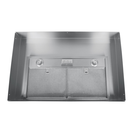
Page 21: Step 7 Install Filters
Installation Instructions STEP 7 INSTALL FILTERS STEP 8 FINALIZE INSTALLATION 1. Remove protective film from the filters. 1. Check to be sure all tape and packaging materials have been removed. 2. Refer to Owner’s Manual for operating instructions. Clip 2. Tip the filter into the back tab slots and lift up. While maintaining slight backward pressure on filter, open clip and press into place with two hands.