
Related Manuals for WaterLogic WL800 – MAX II


Summary of Contents for WaterLogic WL800 – MAX II
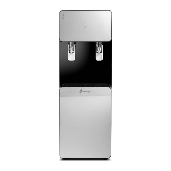
- Page 1 WL800 – MAX II OPERATING, INSTALLATION, AND SERVICE MANUAL Waterlogic Commercial Products, LLC 11710 Stonegate Circle Omaha, NE 68164 (800) 288-1891 www.waterlogic.us...
-
Page 2: Table Of Contents
WL800 OPERATING, INSTALLATION, AND SERVICE MANUAL Congratulations on your choice of the Waterlogic WL800 water treatment system. The WL800 is a fully programmable self-contained model that dispenses cold, hot, extra-hot, and premium sparkling water. Every WL800 includes: High Performance Multi-Stage Filtration Recirculating Ultraviolet (UV) Purification The Waterlogic WL800 provides exceptional quality and great tasting water with every use. -
Page 3: Features And Benefits
WL800 FEATURES AND BENEFITS Cold and Hot Water Cold and Hot Water Selections to meet your customers demands. High Volume Storage and Water Capacity 16 liters of Cold Water Tank Capacity and 3.5 liters of Hot Tank Capacity Large Dispense Area 11.7 inch dispense height, ideal for filling large jogs and carafes Child Safeguard Hot Water safety feature to protect against accidental usage. -
Page 4: Certifications
Intertek Labs (ETL) Certified the WL800 to ANSI/UL 399 Standard for Drinking Water Coolers. BPA Free - Waterlogic tests for BPA and declares that all of its products are Bisphenol-A FREE and contain no harmful BPA plastics. Energy Star Certified... -
Page 5: Introduction
Waterlogic and Authorized Waterlogic Dealers employ trained service personnel who are experienced in the installation, function and repair of Waterlogic equipment. This publication is written for use by these qualified individuals. Waterlogic encourages users to learn about products, however, we believe that product knowledge and service is best obtained by consulting Waterlogic or an Authorized Waterlogic Dealer. -
Page 6: Safety Precautions
SAFETY PRECAUTIONS Basic safety precautions should be followed, including the following: DANGER! If incorrectly installed, operated or maintained, this product can cause death or severe injury. Those who install, operate, or maintain this product should be trained in its proper use, warned of its dangers, and should read the entire manual before attempting to install, operate, or maintain this product. -
Page 7: Model And Part Designations
MODEL/PART DESIGNATIONS BRAND NAME DESCRIPTION MODEL – PART NUMBER WL800 Waterlogic WL800 – Cold and Hot 16-MAZH2 SPECIFICATIONS ITEM WL800 Water Connection ¼” Quick Connect Cold Water Temperature – Factory Set Point 41° - 5°C Cold Water Temperature (Adjustable) 34° - 54° F. (1.1° - 12.2°C) Hot Water Temperature 158°... -
Page 8: Operating Instructions
OPERATING INSTRUCTIONS Dispensing Water Cold Water Selection Push the cup-touch Hot Water Selection Press the Hot Water Safety Button and push the cup touch lever. WL800 Operating, Installation, and Service Manual Page 8 - Revision: 5-14-2015... -
Page 9: Control Panel Instructions
Control Panel Instructions Sleep Mode Button The above picture shows front LCD display and control panel for the Waterlogic WL800 . Button Operational Use Heating LED is on when heater is working Chilling LED is on when cooling system is working LED is on when UV sterilization light is on. -
Page 10: Hot Tank Principles Of Operation
HOT TANK PRINCIPLES OF OPERATION All Waterlogic Hot Tanks have a built in Vent or Expansion Chamber in the top of the tank except for WL270 (GF) units. The Vent Chamber allows for expansion of the water when it is heated. -
Page 11: Flow Diagram
WL800 FLOW DIAGRAM The WL800 is a 4-step Water Filtration system Step 1: PLUS SENDIMENT FILTER (Part Number 16-1000). This plus sediment filter has the functions to reduce sediment (rust, dirt, sand) from feed water and to protect membrane and pre-carbon filter from being plugged. -
Page 12: Disassembling And Refitting Instructions
DISASSEMBLING AND REFITTING INSTRUCTIONS Exercise Caution not to damage or deform any parts when disassembling the system. Refit the system in the reverse order of disassembling. Before disassembling the WL800 1. Block the main water by closing the main water supply valve. 2. - Page 13 REMOVING TOP COVER ASSEMBLY Remove Top cover Assembly in direction shown Remove Silicone Overheating Hose Remove the nine clips on the Cap-Main Tank Assembly Remove Cap-Main Tank Assembly in direction shown WL800 Operating, Installation, and Service Manual Page 13 - Revision: 5-14-2015...
- Page 14 Remove the ceramic filter in the direction shown Remove separator board in direction shown Remove Connector-Cold Water Extraction in direction shown WL800 Operating, Installation, and Service Manual Page 14 - Revision: 5-14-2015...
- Page 15 REMOVING FRONT COVER LOWER ASSEMBLY Remove Grill in direction shown Detach the Grill Tray Assembly as shown Remove the screw (THT 4X10) located on the Front Cover Lower Assembly as shown. Press down on the Front Cover Lower Assembly and remove in the direction shown WL800 Operating, Installation, and Service Manual Page 15 - Revision: 5-14-2015...
- Page 16 REMOVING UPPER COVER LOWER ASSEMBLY Remove the two screws (THT 4X10) from the Front Cover Upper Assembly Remove the two screws (THT 4X10) from the Front Cover Upper Assembly Lift up the Dispensing Handles Lift the Front Cover Upper Assembly and remove in direction shown WL800 Operating, Installation, and Service Manual Page 16 - Revision: 5-14-2015...
- Page 17 Remove the connector from PBA Cover Front Assembly Remove the two screws (THT 4X12) from PBA Cover Front Assembly Remove the two screws (THT 4X8) from PBA Front Assembly WL800 Operating, Installation, and Service Manual Page 17 - Revision: 5-14-2015...
- Page 18 DISASSEMBLING FAUCET ASSEMBLY HOT WATER FAUCET SAFETY ASSEMBLY Remove the two THT 4x10 screws from the Hot Water Faucet Safety Assembly With a flathead screwdriver, remove the hose connected to the Hot Water Faucet Safety Assembly COLD WATER FAUCET ASSEMBLY Remove the two THT 4x10 screws from the Cold Water Faucet Assembly With a flathead screwdriver, remove the hose connected to...
- Page 19 FAUCET BRACKET Remove the four THT 4x10 screws from the Faucet Bracket WL800 Operating, Installation, and Service Manual Page 19 - Revision: 5-14-2015...
- Page 20 DISASSEMBLING PBA ASSEMBLY PBA MAIN ASSEMBLY Press down on hooks to remove the PBA Cover Remove all connectors from the PBA Assembly Remove the two screws THT 4x8 on the PBA Main Assembly PBA SMPS Remove the three screws THT 4x8 on the PBA SMPS WL800 Operating, Installation, and Service Manual Page 20 - Revision: 5-14-2015...
- Page 21 PBA Bracket Remove the two screws THT 4x10 on the PBA Bracket Ballast Detach the connector from the Ballast Remove the two screws THT 4x8 from Ballast WL800 Operating, Installation, and Service Manual Page 21 - Revision: 5-14-2015...
- Page 22 DISASSEMBLING FILTERS FILTER Remove fittings attached to the filters with a flathead screwdriver. Remove all Filters in direction shown. VALVE AUTOMATION DRAIN CONTROL Remove Valve-Automation Drain Control connected to the filter with a flathead screwdriver. WL800 Operating, Installation, and Service Manual Page 22 - Revision: 5-14-2015...
- Page 23 DISASSEMBLING FILTER BRACKETS COLD WATER CONNECTOR DRAIN ASSEMBLY Remove the Cold Water Connector Drain Cap Rotate the Cold Water Connector Drain Assembly in the direction shown with needle nose pliers. Line up the Cold Water Connector Drain Assembly to the groove on the Filter Bracket.
- Page 24 Rotate the Hot Water Connector Drain Assembly in the direction shown with needle nose pliers. Line up the Hot Water Connector Drain Assembly to the groove on the Filter Bracket. Push it in the direction as shown with needle nose pliers. VALVE FEED NOS Remove the connector from Valve Feed Nos Remove the fitting attached to Valve Feed Nos with a...
- Page 25 Remove the single screw THT 4x8 on Valve Feed Nos. SENSOR-E LPS ASSEMBLY Remove the fitting attached to Sensor E LPS Assembly with a flat head screwdriver. Remove the single screw THT 4x8 on the SENSOR-E LPS Assembly. FILTER BRACKET Remove the four screws THT 4x10 on the Bracket Filter.
- Page 26 Completely remove the Bracket Filter in the direction shown. CLIP FILTER C2 Remove the eight screws THT 4x12 on Clip Filter C2. CAPACITOR RUNNING Remove the connector from Capacitor Running. Remove the single screw THT 4x16 on Capacitor Running. WL800 Operating, Installation, and Service Manual Page 26 - Revision: 5-14-2015...
- Page 27 DISASSEMBLING MODULE ASSEMBLY BRACKETS ULTRAVIOLET STERILIZER MODULE ASSEMBLY Remove the hose connected to the Ultraviolet Sterilizer Module Assembly with a flathead screwdriver. Remove the Ultraviolet sterilizer in direction shown. ULTRAVIOLET STERILIZER CLIP SUS Remove the two screws THT 4x12 on the ULTRAVIOLET STERILIZER CLIP SUS OVERFLOW SENSOR Remove the two rubber tubes connected to the Overflow...
- Page 28 Remove the two screws on the Sensor Overflow with a Phillips screwdriver. CTS WATER LEVEL N SENSOR Remove the clip on the CTS Water Level N Sensor with a Flathead Screwdriver. Remove the CTS Water level N in direction shown. CTS WATER LEVEL P SENSOR Remove the CTS Water Level P Sensor Clip with a Flathead Screwdriver.
- Page 29 Remove the CTS Water Level P Sensor in direction as shown. COLD TEMPERATURE SENSOR ASSEMBLY Remove the two screws THT 4x10 on the Cold Temperature Sensor Assembly Remove the Cold Temperature Assembly Sensor in direction as shown. STRAIGHT CONNECTOR DISASSEMBLY Remove the two screws THT 4x10 on the Straight Connector Assembly WL800 Operating, Installation, and Service Manual...
- Page 30 FITTING Remove the fitting attached to the Main Tank Assembly with a flathead screwdriver in direction shown. WL800 Operating, Installation, and Service Manual Page 30 - Revision: 5-14-2015...
- Page 31 REAR COVER DISASSEMBLY Rear Cover A Remove the four screws THT 4x12 on the Rear A Cover Remove Rear A Cover in direction shown Remove the four screws THT 4x12 on the Rear A Cover Remove the Rear A Cover in direction shown AIR FILTER WL800 Operating, Installation, and Service Manual Page 31 - Revision: 5-14-2015...
- Page 32 Remove the two screws THT 4x10 on Air Filter Pull the Air Filter towards you and remove in the direction shown. REAR B COVER ASSEMBLY Remove the four screws THT 4x12 on the Rear B Cover Assembly. Remove the Rear B Cover in the direction shown. POWER CORD ASSEMBLY WL800 Operating, Installation, and Service Manual Page 32 - Revision: 5-14-2015...
- Page 33 Remove the single screw PHT 3x8 (washer) on the Power Cord Assembly. Remove the Power Cord Assembly in direction shown. WL800 Operating, Installation, and Service Manual Page 33 - Revision: 5-14-2015...
-
Page 34: Pre-Installation Instructions
• ¼” Plastic Tubing, at least 4 feet in length, and assorted ¼” quick connect fittings • TDS Meter and Test Strips for measuring chlorine - Optional 1. Unpack the Waterlogic WL800 and check exterior for damage. WARNING! WL800 IS HEAVY. - Page 35 Flush Filters CAUTION! FILTER FLUSH REQUIRED. In order for our filters to perform as represented and to provide the best quality water possible, it is essential that filters be replaced periodically. The frequency of filter changes depends upon your water quality and your water usage. For example, if there is a lot of sediment and/or particles in your water, then you will have to change your filters more frequently than a location with little to no sediment.
- Page 36 USE SANITIZER COMPATIBLE WITH STAINLESS STEEL AND ACETAL PLASTIC. CAUTION! Do not allow the sanitizer solution to remain in the system for more then 10-15 minutes unless otherwise directed by the sanitizer manufacturer. Flushing the Sanitizer from the Machine 10. Place a pitcher, catch basin, or other container under the faucet of the WL800. 11.
-
Page 37: Draining Instructions
WL800 DRAINING INSTRUCTIONS WARNING! WL800 IS A HEAVY OBJECT. 1. Turn off water supply and disconnect from unit. 2. Unplug power supply 3. Remove drip tray and lower front panel. Remove Grill in direction shown Detach the Grill Tray Assembly as shown Remove the screw (THT 4X10) located on the Front Cover Lower Assembly as shown. - Page 38 Press down on the Front Cover Lower Assembly and remove in the direction shown 4. Connect drain tube. 5. Replace lower front panel and drip tray. WL800 Operating, Installation, and Service Manual Page 38 - Revision: 5-14-2015...
-
Page 39: Installation Instructions
80F, require a minimum of 4-inches clearance for proper heat dissipation and efficient operation. USE A WATER PRESSURE REGULATOR. Waterlogic will not be responsible for injury or CAUTION! damage caused by excessive water pressure. Operating pressure must be 40 psi to 60 psi. Be aware any of potential pressure surges caused by building/municipal pumping stations. - Page 40 Waterlogic requires the use of a water pressure regulator. Water feed pressure must be between 40- 60 psi. Turn on the water supply and check for leaks. 1. Connect the power cord to the back of the Waterlogic WL800 and to a 120 Volt supply. 2. Allow unit to fill.
-
Page 41: Service Instructions
1. Visually inspect all electrical and water connections for signs of wear or damage. DANGER! HIGH VOLTAGE ELECTRICAL HAZARD. Unplug before inspection and service. 2. Waterlogic recommends changing the UV Lamp every 12 months. ULTRAVIOLET RADIATION. Protect your skin and eyes against ultraviolet rays. WARNING! Never look directly at an operating UV light. -
Page 42: Replacement Components
3123954 Every 12 months, or as required WLUSA P/N 16-5740 Replacement parts can be obtained from Waterlogic or an Authorized Waterlogic Dealer. See Parts Layouts, Drawings, and Lists for additional repair parts. Hot Tank 3123938 – WLUSA P/N 16-5020 Service Hot Tank (with controls) must be replaced at least every 5 years. -
Page 43: Hot Tank Descaling Instructions
The hot tank is made from stainless steel. Ensure descaling solution is compatible with stainless and always flush the unit completely. Dispose in an environmentally safe manner. See Hot Tank Descaling Video and training procedure located on the Partner Area of the Waterlogic Website for more detailed instructions. - Page 44 6. Remove Drip Tray and Lower Front Panel 7. Drain Unit using Supplied Drain Tube 8. Open Reservoir Cover 9. Pour Descale solution into Hot Tank using a funnel. 10. Turn on Water and Power Supplies 11. Allow unit to refill 12.
-
Page 45: Drawing And Parts List
WL800 EXPLODED VIEW AND PARTS LIST WL800 Operating, Installation, and Service Manual Page 45 - Revision: 5-14-2015... - Page 46 WL800 PARTS LIST Image Description WLUSA P/N 3103311 CASTER-B 16-5000 CASTER-E 16-5005 3306158 3123934 FAN-UNIT ASSY 3122366 PUMP-BOOSTER COVER-SIDE L ASSY 3123936 16-5010 3123937 COVER-SIDE R ASSY 16-5015 3101463 HANDLE 3123938 HEATING TANK ASSY 16-5020 CONNECTOR-HOT WATER DRAIN 3306113 16-5025 ASSY 3306116 BALLAST...
- Page 47 3123940 16-5040 PBA-SMPS 3110507 COVER-REAR A 16-5045 3110508 COVER-REAR B ASSY 16-5050 3210636 FILTER-AIR 16-5055 3123945 COVER-FRONT UPPER ASSY 16-5060 3123947 PBA-COVER FRONT ASSY 16-5065 3123948 COVER-FRONT LOWER ASSY 16-5070 3123949 TRAY ASSY 16-5075 3224223 GRILLE 16-5080 3123950 COVER-TOP ASSY 16-5080 WL800 Operating, Installation, and Service Manual Page 47 - Revision: 5-14-2015...
- Page 48 3123944 CAP-MAIN TANK ASSY 16-5090 3112502 CLIP-MAIN TANK SEALING 16-5095 3306123 SEPARATOR-BOARD 16-5100 3110565 16-5105 SENSOR-COLD TEMPERATURE ASSY 3306120 SENSOR-CTS WATER LEVEL N 16-5110 3306121 SENSOR-CTS WATER LEVEL P 16-5115 3306122 SENSOR-OVER FLOW HARNESS-OVER FLOW SENSOR 3110569 16-5120 ASSY 3306114 FAUCET-HOT WATER SAFETY ASSY 16-5125 3123952...
- Page 49 16-5135 3306115 RUBBER-FAUCET LEVER ULTRA-VIOLET STERILIZER- 3123954 16-5140 MODULE ASSY VALVE-AUTOMATION DRAIN 3306125 CONTROL 3306127 CLIP-FILTER C2 16-5145 CONNECTOR-COLD WATER DRAIN 3103373 16-5150 ASSY 3105086 VALVE-FEED NOS 16-5150 shown 3116166 SENSOR-E LPS ASSY 16-5155 shown 3123935 SENSOR-LEAKAGE shown 3306111 BIMETAL 16-5160 shown WL800 Operating, Installation, and Service Manual...
- Page 50 3306112 16-5170 SENSOR-Hot Water Temperature shown 3224211 POWER CORD ASSY 16-5175 shown 3306117 SNAP RING-E-RING shown 3100029 SPRING shown 3306118 SUPPORT shown 3103235 CLIP-Ultra-Violet Sterilizer SUS shown 3123955 HOSE-UV FILTER shown 3306124 HOSE-TAP shown 16-5185 3300750 FITTING-ELBOW (white) shown WL800 Operating, Installation, and Service Manual Page 50 - Revision: 5-14-2015...
- Page 51 3114063 16-5185 VALVE-ELBOW CHECK shown 3105091 FITTING-ELBOW (gray) 16-5190 shown 3302908 FITTING-STRAIGHT (gray) shown 3306126 CAP-FAUCET 16-5195 shown WL800 Operating, Installation, and Service Manual Page 51 - Revision: 5-14-2015...
-
Page 52: Electrical Diagram
WL800 ELECTRICAL DIAGRAM DANGER! HIGH VOLTAGE ELECTRICAL HAZARD. PCB (Printed Circuit Board) contains High Voltage. Only trained and qualified technicians should attempt live testing. WL800 Operating, Installation, and Service Manual Page 52 - Revision: 5-14-2015... -
Page 53: Cable Specifications
CABLE SPECIFICATIONS WL800 Operating, Installation, and Service Manual Page 53 - Revision: 5-14-2015... - Page 54 WL800 Operating, Installation, and Service Manual Page 54 - Revision: 5-14-2015...
- Page 55 WL800 Operating, Installation, and Service Manual Page 55 - Revision: 5-14-2015...
-
Page 56: Circuit Diagrams
WL800 CIRCUIT DIAGRAMS MAIN PBA WL800 Operating, Installation, and Service Manual Page 56 - Revision: 5-14-2015... - Page 57 WL800 Operating, Installation, and Service Manual Page 57 - Revision: 5-14-2015...
- Page 58 FRONT PBA WL800 Operating, Installation, and Service Manual Page 58 - Revision: 5-14-2015...
-
Page 59: Pba Location Diagrams
PBA LOCATION DIAGRAM MAIN PBA WL800 Operating, Installation, and Service Manual Page 59 - Revision: 5-14-2015... - Page 60 WL800 Operating, Installation, and Service Manual Page 60 - Revision: 5-14-2015...
- Page 61 WL800 Operating, Installation, and Service Manual Page 61 - Revision: 5-14-2015...
- Page 62 SMPS WL800 Operating, Installation, and Service Manual Page 62 - Revision: 5-14-2015...
- Page 63 SMPS WL800 Operating, Installation, and Service Manual Page 63 - Revision: 5-14-2015...
-
Page 64: Fault Codes
FAULT CODES UV LED Blinking – UV Error Possible Reason Solution UV Lamp or Pump is Not Check Connections to UV Lamp / Pump Assembly. Replace Operational UV Lamp / Pump Assembly as needed. Heating and Service LED Blink Simultaneously – Hot Water Sensor Error Possible Reason Solution 1. - Page 65 Chilling and Service LED Alternate Blinking – Full Water Level Error Possible Reason Solution Low Level and Overflow Check connection to low water level sensor. Sensors indicted water but full level sensor is not detected Replace full water level sensor Heating, Chilling and Service LED Sequentially Blink Possible Reason Solution...
-
Page 66: Troubleshooting
TROUBLESHOOTING POWER SUPPLY FAULT WL800 Operating, Installation, and Service Manual Page 66 - Revision: 5-14-2015... - Page 67 TROUBLESHOOTING POWER SUPPLY FAULT - continued WL800 Operating, Installation, and Service Manual Page 67 - Revision: 5-14-2015...
- Page 68 TROUBLESHOOTING HOT WATER MALFUNCTION WL800 Operating, Installation, and Service Manual Page 68 - Revision: 5-14-2015...
- Page 69 TROUBLESHOOTING HOT WATER MALFUNCTION WL800 Operating, Installation, and Service Manual Page 69 - Revision: 5-14-2015...
- Page 70 TROUBLESHOOTING COLD WATER MALFUNCTION WL800 Operating, Installation, and Service Manual Page 70 - Revision: 5-14-2015...
- Page 71 TROUBLESHOOTING COLD WATER MALFUNCTION continued WL800 Operating, Installation, and Service Manual Page 71 - Revision: 5-14-2015...
- Page 72 TROUBLESHOOTING UV MODULE MALFUNCTION WL800 Operating, Installation, and Service Manual Page 72 - Revision: 5-14-2015...
- Page 73 TROUBLESHOOTING DISPENSING MALFUNCTION WL800 Operating, Installation, and Service Manual Page 73 - Revision: 5-14-2015...
- Page 74 TROUBLESHOOTING DISPENSING MALFUNCTION WL800 Operating, Installation, and Service Manual Page 74 - Revision: 5-14-2015...
-
Page 75: Warranty
Waterlogic will approve of return in writing and will issue a Return Authorization which you must obtain prior to shipping the product. You are responsible for the cost of freight in to Waterlogic. Waterlogic and its affiliated companies hereby limit the duration of any and all implied warranties to a maximum period of three (3) years from the date of purchase including, but not limited to, the implied warranties of merchantability and fitness for a particular purpose.