Table of Contents
Advertisement
Quick Links
3
YEARS
Warranty
Please read and understand this instruction manual carefully
before the installation and operation of this equipment.
(Power Source)
TECHNOLOGY
Lift Arc DC/TIG
240 Volt
ADVANTAGE
OPERATING MANUAL
1
MIG-TIG-STICK BUIL T-IN
TECHNOLOGY
MIG-TIG-STICK BUIL T-IN
ADVANTAGE
TECHNOLOGY
Standard
V oltage Reduction Device
MIG / MAG
TECHNOLOGY
MIG-TIG-STICK
Plasma CUT
TECHNOLOGY
MIG-TIG-STICK
KUMJR350K
©
Welding Guns Of Australia PTY LTD 2012
L
Advertisement
Table of Contents

Related Manuals for Unimig KUMJR350K


Summary of Contents for Unimig KUMJR350K
- Page 1 V oltage Reduction Device MIG / MAG TECHNOLOGY TECHNOLOGY MIG-TIG-STICK Plasma CUT TECHNOLOGY ADVANTAGE MIG-TIG-STICK OPERATING MANUAL KUMJR350K Please read and understand this instruction manual carefully before the installation and operation of this equipment. © Welding Guns Of Australia PTY LTD 2012...
-
Page 2: Safety
• Product will only be replaced if repair is not possible • Please view full Warranty term and conditions supplied with machine or at www.unimig.com.au/ warranty.asp or at the back of this manual. -
Page 3: Table Of Contents
CONTENTS PAGE Warranty Safety Caution, Maintenance and Trouble Shooting Technical Data, Product Information Machine Layout Pictogram Installation & Operation for MMA (stick) Welding MMA (Stick) Welding) 12-13 Installation & Operation for MIG Welding 14-15 Wire Feed Drive Rollers Wire Installation and Wire Feeder Set Up Mig Torch Liner Installation Torch and Wire Feeder Setup for Aluminium Wire 19-20... - Page 4 SAFETY Welding and cutting equipment can be dangerous to both the operator and people in or near the surrounding working area, if the equipment is not correctly operated. Equipment must only be used under the strict and comprehensive observance of all relevant safety regulations. Read and understand this instruction manual carefully before the installation and operation of this equipment.
- Page 5 Fire hazard. Welding on closed containers, such as tanks,drums, or pipes, can cause them to explode. Flying sparks from the welding arc, hot work piece, and hot equipment can cause fires and burns. Accidental contact of electrode to metal objects can cause sparks, explosion, overheating, or fire.
-
Page 6: Working Environment
CAUTION 1. Working Environment. 1.1 The environment in which this welding equipment is installed must be free of grinding dust, corrosive chemicals, flammable gas or materials etc, and at no more than maximum of 80% humidity. 1.2 When using the machine outdoors protect the machine from direct sun light, rain water and snow etc; the temperature of working environment should be maintained within -10°C to +40°C. - Page 7 ATTENTION! - CHECK FOR GAS LEAKAGE At initial set up and at regular intervals we recommend to check for gas leakage Recommended procedure is as follows: 1. Connect the regulator and gas hose assembly and tighten all connectors and clamps. 2.
-
Page 8: Technical Data
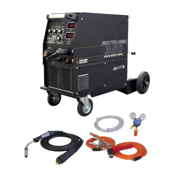
3 years on machine Tig Torch Option SpoolGun Option Overview The KUMJR350K is an inverter-based multi-function Mig welding machine with added MMA and Tig function. The Mig function allows you to weld with both Gas Shielded and Gasless wire applications. Easy step less adjustment of voltage and wire feed make for easy setting of welding parameters giving excellent, professional welding results. Wire inch gives easy feeding of the wire during set up without gas wastage and the Burn Back adjustment leaves the wire stick out ready for the next weld. An additional feature is the Spoolgun ready function that allows the simple con- nection of the SPG200 Spoolgun for the use of thin or softer wires that don’t have the column strength to feed through standard mig torches, such as aluminium wire. Added MMA welding capability delivers easy and high quality welding using electrodes, including cast Iron, stainless and low hydrogen. Connection of the 26V tig torch provides quality DC Tig with Lift Arc start for welding of steel, stainless steel and copper. The machine is industrial rated and of solid construction, large industrial wheels allows easy and smooth manoeuvrability. Ideal for general engineers, maintenance workshop, rural workshop, tafe colleges panel beaters,. Designed and built to our specification. Certified to - AS/NZ60974.1 Product Code: KUMJR350K Standard Package includes: KUMJR350K Machine, Mig Torch x 4m, Earth Lead & Arc Lead 35mm x 4m, Regulator, 2M gas hose... - Page 9 Front Machine Layout Description FRONT PANEL LAYOUT Amperage Meter Voltage Meter Wire Inch Button Mig/MMA/Tig Mode Selector Switch Wire Feed Adjustment Knob (MIG/MAG) Standard Mig / Spoolgun Selector Switch “-” Output terminal SpoolGun Power Supply Connection “+” Output terminal 10. Euro Mig Torch Connector (MIG/MAG) 11.
- Page 10 Installation set up for MMA (Stick) Welding with UNI-MIG-MIG350MTS (1) Turn the power source on and select the MMA function with the Tig/MMA/Mig selector switch. (2) Connection of Output Cables Two sockets are available on this welding machine. For MMA welding the electrode holder is shown be connected to the positive socket, while the earth lead (work piece) is connected to the negative socket, this is known as DC+ polarity.
- Page 11 MMA (Manual Metal Arc) Welding One of the most common types of arc welding is manual metal arc welding (MMA) or stick welding. An electric cur- rent is used to strike an arc between the base material and a consumable electrode rod or ‘stick’. The electrode rod is made of a material that is compatible with the base material being welded and is covered with a flux that gives off gaseous vapours that serve as a shielding gas and providing a layer of slag, both of which protect the weld area from atmospheric contamination.
- Page 12 MMA (Stick) Welding Fundamentals Electrode Selection As a general rule, the selection of an electrode is straight forward,in that it is only a matter of selecting an electrode of similar composition to the parent metal. However, for some metals there is a choice of several electrodes, each of which has particular properties to suit specific classes of work.
- Page 13 Installation set up for MIG Welding with UNI-MIG-MIG350MTS (1) Select the MIG function with the Tig/MMA/Mig selector switch. (2) Select Standard using the Standard/Spool Gun selector switch. (3) Plug the welding torch into the Euro Mig torch connection socket on the front panel, and tighten it. (4) Insert the earth cable plug into the required polarity and tighten - negative for gas shielded wires positive for gas less wires.
- Page 14 Continued set up for MIG Welding with UNI-MIG-MIG350MTS (9) Align the wire into the groove of the drive roller and close down the top roller making sure the wire is in the groove of the bottom drive roller, lock the pressure arm into place. Apply a medium amount of pressure to the drive roller.
- Page 15 Wire Feed Roller Selection The importance of smooth consistent wire feeding during MIG welding cannot be emphasized enough. Simply put the smoother the wire feed then the better the welding will be. Feed rollers or drive rollers are used to feed the wire mechanically along the length of the welding gun. Feed rollers are designed to be used for certain types of welding wire and they have different types of grooves machined in them to accommodate the different types of wire.
- Page 16 Wire Installation and Set Up Guide Again the importance of smooth consistent wire feeding during MIG welding cannot be emphasized enough. The correct installation of the wire spool and the wire into the wire feed unit is critical to achieving an even and consistent wire feed.
-
Page 17: Mig Torch Liner Installation
Mig Torch Liner Installation (1) Lay the torch out straight on the ground and remove the front end parts (2) Remove the liner retaining nut. (3) Carefully pull the liner out of the torch cable assembly (4) Select the correct new liner and carefully unravel avoiding putting any kinks in the liner, if you kink the liner it will make it no good and will require replacement. - Page 18 Torch & Wire Feed Set Up for Aluminium Wire (1) Lay the torch out straight on the ground and remove the front end parts (2) Remove the liner retaining nut. (3) Carefully pull the liner out of the torch cable assembly (4) Select a Polymide or liner, carefully and slowly feed the liner in short forward movements down the cable assembly all the way through and out the torch neck end.
- Page 19 Continued Torch & Wire Feed Set Up for Aluminium Wire (10) Remove the inlet guide tube from the front end machine euro connector using long nose pliers. (11) Carefully feed the extended Polymide liner section into the inlet guide tube hole of the machine euro connector (12) Feed the extended Polymide liner all the way up and over the drive roller (13) Tighten the torch euro connection to the machine euro connector...
- Page 20 MIG (Metal Inert Gas) Welding Definition of MIG Welding MIG (metal inert gas) welding also known as GMAW (gas metal arc welding) or MAG (metal active gas welding), is a semi-automatic or automatic arc welding process in which a continuous and consumable wire electrode and a shielding gas are fed through a weld- ing gun.
- Page 21 MIG (Metal Inert Gas) Welding Short Circuit Transfer - Short circuit transfer is the most common used method whereby the wire electrode is fed continuously down the welding torch through to and exiting the contact tip. The wire touches the work piece and causes a short circuit the wire heats up and begins to form a molten bead, the bead separates from the end of the wire and forms a droplet that is transferred into the weld pool.
- Page 22 Basic MIG Welding Good weld quality and weld profile depends on gun angle, direction of travel, electrode extension (stick out), travel speed, thickness of base metal, wire feed speed (amperage) and arc voltage. To follow are some basic guides to assist with your setup. Gun Position - Travel Direction, Work Angle Gun position or technique usually refers to how the wire is directed at the base metal, the angle and travel direction chosen.
- Page 23 Travel Angle - Travel angle is the right to left angle relative to the direction of welding. A travel angle of 5°- 15° is ideal and produces a good level of control over the weld pool. A travel angle greater that 20° will give an unstable arc condition with poor weld metal transfer, less penetration, high levels of spatter, poor gas shield and poor quality finished weld.
- Page 24 Travel Speed - Travel speed is the rate that the gun is moved along the weld joint and is usually measured in mm per minute. Travel speeds can vary depending on conditions and the welders skill and is limited to the welders ability to control the weld pool. Push technique allows faster travel speeds than Drag technique.
- Page 25 Wire types and sizes - Use the correct wire type for the base metal being welded. Use stainless steel wire for stainless steel, aluminium wires for aluminium and steel wires for steel. Use a smaller diameter wire for thin base metals. For thicker materials use a larger wire diameter and larger machine, check the recommended welding capability of you machine.
- Page 26 Installation set up of the Spool Gun with UNI-MIG-MIG350MTS (1) Switch on the machine, select the MIG function with the Tig/MMA/Mig selector switch. (2) Select Spool Gun using the Standard/Spool Gun selector switch. (3) Connect the Spool Gun to the Euro Mig torch connection socket on the front panel, and tighten it. Connect the Spool Gun control cable to the receptacle and tighten it.
- Page 27 Continued set up of the Spool Gun with UNI-MIG-MIG350MTS Carefully feed the wire over the drive roller into the outlet guide tube, feed through into the torch neck. Check that the drive roller being used complies with the wire diameter, replace the roller if necessary. (10) Align the wire into the groove of the drive roller and release the tension arm making sure the wire is in the groove of the drive roller.
-
Page 28: Dc Tig Welding
Installation and set up for DC TIG welding with UNI-MIG-MIG350MTS (1) Switch on the machine, select the TIG function with the TIG/MMA/Mig selector switch. (2) Insert the power cable plug of the Tig torch into the Negative socket on the front of the machine and tighten it. -
Page 29: Tungsten Electrodes
LIFT ARC DC TIG Operation (5) Make sure the front end parts of the tig torch are correctly assembled, use the correct size and type of tungsten electrode for the job, the tungsten electrode requires a sharpened point for DC welding. (6) Turn on the Gas Valve located on the tig torch handle. -
Page 30: Dc Tig Welding
DC TIG Welding The DC power source uses what is known as DC (direct current) in which the main elec- trical component known as electrons flow in only one direction from the negative pole (terminal) to the positive pole (terminal). In the DC electrical circuit there is an electrical principle at work which should always be taken into account when using any DC circuit. -
Page 31: Tig Welding With Filler Wire Technique
TIG Welding Fusion Technique Manual TIG welding is often considered the most difficult of all the welding processes. Because the welder must maintain a short arc length, great care and skill are required to prevent contact between the electrode and the workpiece. Similar to Oxygen Acety- lene torch welding, Tig welding normally requires two hands and in most instances requires the welder to manually feed a filler wire into the weld pool with one hand while manipulating the welding torch in the other. -
Page 32: Tungsten Electrodes
Tungsten Electrodes Tungsten is a rare metallic element used for manufacturing TIG welding electrodes. The TIG process relies on tung- sten’s hardness and high-temperature resistance to carry the welding current to the arc. Tungsten has the highest melting point of any metal, 3,410 degrees Celsius. Tungsten electrodes are nonconsumable and come in a variety of sizes, they are made from pure tungsten or an al- loy of tungsten and other rare earth elements. -
Page 33: Tungsten Preparation
Tungsten Preparation Always use wheels when grinding and cutting. While tungsten is a very hard material, the surface of a DIAMOND diamond wheel is harder, and this makes for smooth grinding. Grinding without diamond wheels, such as aluminium oxide wheels, can lead to jagged edges, imperfections, or poor surface finishes not visible to the eye that will contrib- ute to weld inconsistency and weld defects. - Page 34 UNI-FLAME AUTOLIFT UNI-FLAME SB36 MIG TORCH Suregrip Series 300A AIR COOLED MIG WELDING TORCH Rating:300A CO² 270A mixed gas EN60974-7 @ 60% duty cycle. 0.8 to 1.2mm wires Front end parts shown on opposite page 17 16 Liners shown on opposite page Torch Model Description Part Number...
- Page 35 UNI-FLAME AUTOLIFT UNI-FLAME SB36 MIG TORCH Suregrip Series Front end consumables SB36 Contact Tips M6 Part Number Description PCT0009-06 Contact Tip Steel (0.6mm) PCT0009-08 Contact Tip Steel (0.8mm) PCT0009-09 Contact Tip Steel (0.9mm) PCT0009-10 Contact Tip Steel (1.0mm) 28.0 PCT0009-12 Contact Tip Steel (1.2mm) PCT0009-16 Contact Tip Steel (1.6mm) PCTZR009-09 Contact Tip Steel Long Life (0.9mm) PCTZR009-12 Contact Tip Steel Long Life (1.2mm) PCTAL0009-09 Contact Tip Aluminium (0.9mm) PCTAL0009-10 Contact Tip Aluminium (1.0mm) PCTAL0009-12 Contact Tip Aluminium (1.2mm) PCT0005-08 Contact Tip Steel M8 (0.8mm)
- Page 36 UNI-FLAME AUTOLIFT UNI-FLAME SPG200 Torch Model Description Part Number XcelArc Spool Gun x 6m SPG200II Spare Parts Part Number Description Part Number Description LMZ2017 Speed Adjusting Knob LMZ2014 Potentiometer LMH2114 Open/Close Button LMZ2015 Push Roll LMH2111 Left-Gun Case LMK2001 Conducting Board LMH2115 Hang Hook EF1101...
- Page 37 UNI-FLAME AUTOLIFT UNI-FLAME SPG20011 Front end consumables SB24 Contact Tips Part Number Description PCT0009-06 Contact Tip Steel (0.6mm) PCT0009-08 Contact Tip Steel (0.8mm) PCT0009-09 Contact Tip Steel (0.9mm) PCT0009-10 Contact Tip Steel (1.0mm) PCT0009-12 Contact Tip Steel (1.2mm) 28.0 PCT0009-16 Contact Tip Steel (1.6mm) PCTZR009-09 Contact Tip Steel Long Life (0.9mm) PCTZR009-12 Contact Tip Steel Long Life (1.2mm) PCTAL0009-09 Contact Tip Aluminium (0.9mm) PCTAL0009-10 Contact Tip Aluminium (1.0mm) PCTAL0009-12 Contact Tip Aluminium (1.2mm) SB24 Tip Holder Part Number Description PCTH24 Contact Tip Holder...
- Page 38 UNI-FLAME AUTOLIFT UNI-FLAME Suregrip Series SR26V ERGO TIG TORCH 200A AIR COOLED TIG WELDING TORCH Rating:200Amp DC, 140Amp AC @35% duty cycle. Front end parts identification on opposite page Switch & remote control wires Torch Model Description Part Number SR26 Suregrip Tig Torch Package c/w QF Gas Connect SR-26-4MCP50 SR-26-8MCP50 SR-26-4MCP25...
- Page 39 UNI-FLAME AUTOLIFT SR26V ERGO TIG TORCH UNI-FLAME Suregrip Series Standard Front End Parts Part # Description Part # Description Part # Description Long Alumina Nozzle Ø 8mm #5L 18CG Cup Gasket 10N30 Collet Body 1.0mm 10N49L Long Alumina Nozzle Ø 10mm #6L 10N31 Collet Body 1.6mm 53N48L...
- Page 40 MIG WELDING TROUBLE SHOOTING The following chart addresses some of the common problems of MIG welding. In all cases of equipment malfunction, the manu- facturer’s recommendations should be strictly adhered to and followed. 1: Excessive Spatter Possible Reason Suggested Remedy Wire feed speed set too high Select lower wire feed speed Voltage too high...
- Page 41 MIG WIRE FEED TROUBLE SHOOTING The following chart addresses some of the common WIRE FEED problems during MIG welding. In all cases of equipment malfunction, the manufacturer’s recommendations should be strictly adhered to and followed. 1: No wire feed Possible Reason Suggested Remedy Wrong mode selected Check that the TIG/MMA/MIG selector switch set to MIG position...
-
Page 42: Tig Welding Trouble Shooting
TIG WELDING TROUBLE SHOOTING The following chart addresses some of the common problems of DC TIG welding. In all cases of equipment malfunction, the manufacturer’s recommendations should be strictly adhered to and followed. 1: Tungsten burning away quickly Possible Reason Suggested Remedy Incorrect Gas or No Gas Use pure Argon. - Page 43 MMA (Stick) WELDING TROUBLE SHOOTING The following chart addresses some of the common problems of MMA welding. In all cases of equipment malfunction, the manufacturer’s recommendations should be strictly adhered to and followed. 1: No arc Possible Reason Suggested Remedy Incomplete welding circuit Check earth lead is connected.
- Page 44 Spare Parts Identification - MIG350MTS Part Number Description Part Number Description J08339 Top Side Panel B06096 EMC PCB D20048 Volt Meter B02466 On/Off Switch D20048 Amp Meter J22011 Shunt B22167 TIG/MMA/Mig Switch D16027-1 Reactor B22212 Standard/ Spool Gun Switch D03211 Transformer C02066 Panel Socket 35-50...
- Page 45 Fax: (02) 9780 4244 Welding Guns Of Australia Pty Ltd Email: sales@unimig.com.au / Web: www.unimig.com.au ABN: 14 001 804 422 Welding Guns Of Australia Pty Ltd (‘Us’, ‘We’) warrants that the following products under UNI-MIG, UNI-TIG, UNI-PLAS, UNI-FLAME, TECNA, T&R, HIT-8SS & ROTA, supplied by Us and purchased by you from an Authorised UNI-MIG, UNI-TIG, UNI-PLAS, UNI-FLAME, TECNA, T&R, HIT-8SS &...
- Page 46 WARRANTY / RETURNS / EXCHANGES We understand that sometimes you may need to return a product you have purchased from Welding Guns Of Australia PTY LTD Authorised Dealer Network, to assist you, we have set out below the Welding Guns Of Australia PTY LTD Returns Policy that you should know.
- Page 47 WARRANTY EXCLUSIONS This Warranty covers Material and Faulty Workmanship defects only. This Warranty does not cover damage caused by: • Normal wear and tear due to usage • Misuse or abusive use of the UNI-MIG, UNI-TIG, UNI-PLAS, UNI-FLAME, TECNA, T&R, HIT-8SS & ROTA, instructions supplied with the product.
- Page 48 UNI-FLAME Welding Guns Of Australia PTY LTD Pty Ltd ABN: 14 001 804 422 PO Box 3033, Lansvale NSW 2166, AUSTRALIA 112 Christina Rd, Villawood, NSW 2163 Phone: (02) 9780 4200 Fax: (02) 9780 4244 Email: sales@unimig.com.au / Web: www.unimig.com.au...