
Related Manuals for Unimig Razor 250


Summary of Contents for Unimig Razor 250
- Page 1 OPERATING MANUAL KUMJRRW250MIG Please read and understand this instruction manual carefully before the installation and operation of this equipment. © Welding Guns Of Australia PTY LTD 2019...
-
Page 2: Warranty
• New product will not be supplied unless Welding Guns Of Australia PTY LTD has inspected product returned for warranty and agrees to replace product. • Product will only be replaced if repair is not possible • Please view full Warranty term and conditions supplied with machine or at www.unimig.com.au/warranty-registration/ or at the back of this manual. REGISTER YOUR MACHINE ONLINE TO RECEIVE AN ADDITIONAL 6 MONTHS ON YOUR WARRANTY Visit unimig.com.au/warranty-registration/ to register your machine. -
Page 3: Table Of Contents
CONTENTS WARRANTY SAFETY RAZOR MIG 250 FEATURES RAZOR MIG 250 FEATURES MACHINE PARTS LAYOUT MIG WITH GAS INSTALLATION GASLESS MIG INSTALLATION WIRE FEED ROLLER SELECTION WIRE INSTALLATION & SET UP GUIDE MIG TORCH LINER INSTALLATION TORCH & WIRE FEED SET UP FOR ALUMINIUM WIRE MIG WELDING GUIDE SPOOL GUN SETUP LIFT ARC DC TIG WELDING SETUP... -
Page 4: Safety
SAFETY Welding and cutting equipment can be dangerous to both the operator and people in or near the surrounding working area, if the equipment is not correctly operated. Equipment must only be used under the strict and comprehensive observance of all relevant safety regulations. Read and understand this instruction manual carefully before the installation and operation of this equipment. - Page 5 SAFETY Fire hazard. Welding/cutting on closed containers, such as tanks,drums, or pipes, can cause them to explode. Flying sparks from the welding/cutting arc, hot work piece, and hot equipment can cause fires and burns. Accidental contact of electrode to metal objects can cause sparks, explosion, overheating, or fire.
- Page 6 SAFETY CAUTION 1. Working Environment. The environment in which this welding/cutting equipment is installed must be free of grinding dust, corrosive chemicals, flammable gas or materials etc, and at no more than maximum of 80% humidity. ii. When using the machine outdoors protect the machine from direct sun light, rain water and snow etc; the temperature of working environment should be maintained within -10°C to +40°C.
- Page 7 SAFETY ATTENTION! - CHECK FOR GAS LEAKAGE At initial set up and at regular intervals we recommend to check for gas leakage Recommended procedure is as follows: 1. Connect the regulator and gas hose assembly and tighten all connectors and clamps. 2.
-
Page 8: Razor Mig 250 Features
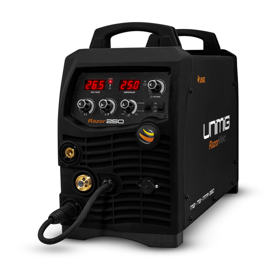
RAZOR MIG 250 FEATURES FEATURES OVERVIEW • 240V Single Phase The RAZOR MIG 250 is a powerful multi-process welder offering MIG, TIG and STICK welding functions, whilst still being a portable machine. This makes the RAZOR MIG • MIG with Gas and Gasless function 250 ideal for welders needing powerful performance both in the workshop and site •... -
Page 9: Razor Mig 250 Features
RAZOR MIG 250 FEATURES TECHNICAL DATA TIG SPECIFICATIONS KUMJRRW250MIG TIG FUNCTION TYPE DC Lift Arc PRIMARY INPUT VOLTAGE 240V Single Phase TIG WELDING CURRENT RANGE 10-250A Single Phase (32 AMP Recommended) or TIG DUTY CYCLE @ 40°C 30% @ 250A SUPPLY PLUG 15 AMP TIG WELDING THICKNESS RANGE... -
Page 10: Machine Parts Layout
MACHINE PARTS LAYOUT 1. Power LED 2. Voltage Display 3. Thermal Overload LED 4. Voltage Control Knob 5. Amperage Control Knob 6. Positive Output Socket 7. Euro MIG Torch Connector 8. Negative Output Socket 9. Amperage Display 10. VRD LED 11. -
Page 11: Mig With Gas Installation
MIG WITH GAS INSTALLATION 4 (+) 4 (-) 1. Select the MIG function with the MIG/MMA selector switch. 2. Select Standard using the Standard/Spool Gun selector switch. 3. Connect the welding torch into the Euro Mig torch connection socket on the front panel, and tighten it. 4. - Page 12 MIG WITH GAS INSTALLATION (9) Close down the top roller bracket and clip the (10) Remove the gas nozzle and contact tip from the (11) Press and hold the inch wire button to feed the pressure arm into place. Apply a medium amount of front end of the MIG torch.
-
Page 13: Gasless Mig Installation
GASLESS MIG INSTALLATION 1. Select the MIG function with the MIG/MMA selector switch. 2. Select Standard using the Standard/Spool Gun selector switch (Inside machine). 3. Connect the weld power cable to the Negative socket and tighten it. 4. Connect the earth cable plug into the Positive socket and tighten it. 5. - Page 14 GASLESS MIG INSTALLATION (9) Close down the top roller bracket and clip the (10) Apply a medium amount of pressure to the drive (11) Remove the gas nozzle and contact tip from the pressure arm into place. Apply a medium amount of roller.
-
Page 15: Wire Feed Roller Selection
WIRE FEED ROLLER SELECTION The importance of smooth consistent wire feeding during MIG welding cannot be emphasized enough. Simply put the smoother the wire feed then the better the welding will be. Feed rollers or drive rollers are used to feed the wire mechanically along the length of the welding gun. Feed rollers are designed to be used for certain types of welding wire and they have different types of grooves machined in them to accommodate the different types of wire. -
Page 16: Wire Installation & Set Up Guide
WIRE INSTALLATION & SET UP GUIDE Again the importance of smooth consistent wire feeding during MIG welding cannot be emphasized enough. The correct installation of the wire spool and the wire into the wire feed unit is critical to achieving an even and consistent wire feed. A high percentage of faults with MIG welders emanate from poor set up of the wire into the wire feeder. -
Page 17: Mig Torch Liner Installation
MIG TORCH LINER INSTALLATION (1) Remove MIG torch front end parts (2) Remove the liner retaining nut (3) Carefully pull out and completely remove the liner (4) Carefully unravel the new liner, avoiding (5) Carefully feed in the new liner down the torch (6) Fit the liner retaining nut and screw only 1/2 creating any kinks in the liner. -
Page 18: Torch & Wire Feed Set Up For Aluminium Wire
TORCH & WIRE FEED SET UP FOR ALUMINIUM WIRE (1) Remove MIG torch front end parts (2) Remove the liner retaining nut (3) Carefully pull out and completely remove the liner (4) Carefully unravel the new liner (5) Carefully feed in the new liner in short (6) Replace the front end parts forward movements down the torch lead all the way to exit the torch neck. - Page 19 TORCH & WIRE FEED SET UP FOR ALUMINIUM WIRE (10) Loosen the inlet guide tube retaining screw. (11) Remove the inlet guide tube using long (12) Carefully feed the Polymide liner into the nose pliers. inlet guide tube hole of the torch Euro receptacle (13) Take the extended Polymide liner all the (14) Tighten and secure the torch Euro (15) Cut the extended Polymide liner with a...
-
Page 20: Mig Welding Guide
MIG WELDING GUIDE MIG (Metal Inert Gas) Welding Definition of MIG Welding - MIG (metal inert gas) welding also known as GMAW (gas metal arc welding) or MAG (metal active gas welding), is a semi-automatic or automatic arc welding process in which a continuous and consumable wire electrode and a shielding gas are fed through a welding gun. - Page 21 MIG WELDING GUIDE MIG (Metal Inert Gas) Welding Short Circuit Transfer - Short circuit transfer is the most common used method whereby the wire electrode is fed continuously down the welding torch through to and exiting the contact tip. The wire touches the work piece and causes a short circuit the wire heats up and begins to form a molten bead, the bead separates from the end of the wire and forms a droplet that is transferred into the weld pool.
- Page 22 MIG WELDING GUIDE Basic MIG Welding Good weld quality and weld profile depends on gun angle, direction of travel, electrode extension (stick out), travel speed, thickness of base metal, wire feed speed (amperage) and arc voltage. To follow are some basic guides to assist with your setup. Gun Position - Travel Direction, Work Angle Gun position or technique usually refers to how the wire is directed at the base metal, the angle and travel direction chosen.
- Page 23 MIG WELDING GUIDE Travel Angle Travel angle is the right to left angle relative to the direction of welding. A travel angle of 5°- 15° is ideal and produces a good level of control over the weld pool. A travel angle greater that 20° will give an unstable arc condition with poor weld metal transfer, less penetration, high levels of spatter, poor gas shield and poor quality finished weld.
- Page 24 MIG WELDING GUIDE Travel Speed Travel speed is the rate that the gun is moved along the weld joint and is usually measured in mm per minute. Travel speeds can vary depending on conditions and the welders skill and is limited to the welders ability to control the weld pool. Push technique allows faster travel speeds than Drag technique.
- Page 25 MIG WELDING GUIDE Wire types and sizes Use the correct wire type for the base metal being welded. Use stainless steel wire for stainless steel, aluminium wires for aluminium and steel wires for steel. Use a smaller diameter wire for thin base metals. For thicker materials use a larger wire diameter and larger machine, check the recommended welding capability of you machine.
-
Page 26: Spool Gun Setup
SPOOL GUN SETUP 1. Switch on the machine, select the MIG function with the MIG/MMA selector switch. 2. Select Spool Gun using the Standard/Spool Gun selector switch. 3. Connect the Spool Gun to the Euro Mig torch connection socket on the front panel, and tighten it. Connect the Spool Gun control cable to the receptacle and tighten it. - Page 27 SPOOL GUN SETUP (9) Carefully feed the wire through the inlet guide tube (10) Check to make sure that the wire passes cleanly (11) Apply a medium amount of pressure using the onto the drive roller through into the outlet guide tube. through the drive roller into the outlet guide tube.
-
Page 28: Lift Arc Dc Tig Welding Setup
LIFT ARC DC TIG WELDING SETUP 1. Switch on the machine, select the TIG function with the TIG/MMA/Mig selector switch. 2. Insert the power cable plug of the TIG torch into the Negative socket on the front of the machine and tighten it. 3. -
Page 29: Lift Arc Dc Tig Operation
LIFT ARC DC TIG OPERATION Lift Arc ignition allows the arc to be started easily in DC TIG by simply touching the tungsten to the work piece and lifting it up to start the arc. This prevents the tungsten tip sticking to the work piece and breaking the tip from the tungsten electrode. -
Page 30: Dc Tig Welding Guide
DC TIG WELDING GUIDE DC TIG WELDING The DC power source uses what is known as DC (direct current) in which the main electrical component known as electrons flow in only one direction from the negative pole (terminal) to the positive pole (terminal). - Page 31 DC TIG WELDING GUIDE TIG WELDING FUSION TECHNIQUE Manual TIG welding is often considered the most difficult of all the welding processes. Because the welder must maintain a short arc length, great care and skill are required to prevent contact between the electrode and the workpiece.
- Page 32 DC TIG WELDING GUIDE TUNGSTEN ELECTRODES Tungsten is a rare metallic element used for manufacturing TIG welding electrodes. The TIG process relies on tungsten’s hardness and high-temperature resistance to carry the welding current to the arc. Tungsten has the highest melting point of any metal, 3,410 degrees Celsius. Tungsten electrodes are non-consumable and come in a variety of sizes, they are made from pure tungsten or an alloy of tungsten and other rare earth elements.
- Page 33 DC TIG WELDING GUIDE TUNGSTEN ELECTRODES RATING FOR WELDING CURRENTS Tungsten Diameter (mm) Diameter at the Tip (mm) Constant Included Angle (°) Current Range (Amps) Current Range (Pulsed Amps) 1.0mm 0.25 11079 22037 1.6mm 18476 05 - 100 1.6mm 25842 10 - 140 2.4mm 33208...
-
Page 34: Mma (Stick) Welding Set Up
MMA (STICK) WELDING SET UP 1. Turn the power source on and select the MMA function with the MIG/ MMA selector switch. 2. Connection of Output Cables Two sockets are available on this welding machine. For MMA welding the electrode holder is shown be connected to the positive socket, while the earth lead (work piece) is connected to the negative socket, this is known as DC+ polarity. -
Page 35: Mma (Stick) Welding Guide
MMA (STICK) WELDING GUIDE MMA (MANUAL METAL ARC) WELDING One of the most common types of arc welding is manual metal arc welding (MMA) or MMA welding. An electric current is used to strike an arc between the base material and a consumable electrode rod or ‘stick’. The electrode rod is made of a material that is compatible with the base material being welded and is covered with a flux that gives off gaseous vapours that serve as a shielding gas and providing a layer of slag, both of which protect the weld area from atmospheric contamination. - Page 36 MMA (STICK) WELDING GUIDE MMA (STICK) WELDING FUNDAMENTALS ELECTRODE SELECTION As a general rule, the selection of an electrode is straight forward,in that it is only a matter of selecting an electrode of similar composition to the parent metal. However, for some metals there is a choice of several electrodes, each of which has particular properties to suit specific classes of work. It is recommend to consult your welding supplier for the correct selection of electrode.
-
Page 37: Sb24 Mig Torch & Spares
SB24 MIG TORCH & SPARES 250A AIR COOLED MIG WELDING TORCH RATING:250A CO² 220A MIXED GAS EN60974-7 @ 60% DUTY CYCLE. 0.8 TO 1.2MM WIRES Part No. Length SB24 SureGrip Ergo Torch Package SB24-3M SB24-4M SB24-5M Part-No Description Part-No Description SNK24 Swan Neck Assembly UB1518... - Page 38 SB24 MIG TORCH & SPARES FRONT END CONSUMABLES SB24 CONTACT TIPS Part-No Description PCT0009-06 Contact Tip Steel (0.6mm) QTY10 PCT0009-08 Contact Tip Steel (0.8mm) QTY10 PCT0009-09 Contact Tip Steel (0.9mm) QTY10 PCT0009-10 Contact Tip Steel (1.0mm) QTY10 28.0 PCT0009-12 Contact Tip Steel (1.2mm) QTY10 PCT0009-16 Contact Tip Steel (1.6mm)
-
Page 39: Mig Welding Trouble Shooting
MIG WELDING TROUBLE SHOOTING The following chart addresses some of the common problems of MIG welding. In all cases of equipment malfunction, the manufacturer’s recommendations should be strictly adhered to and followed. 1: Excessive Spatter Possible Reason Suggested Remedy Wire feed speed set too high Select lower wire feed speed Voltage too high Select a lower voltage setting... -
Page 40: Mig Wire Feed Trouble Shooting
MIG WIRE FEED TROUBLE SHOOTING The following chart addresses some of the common WIRE FEED problems during MIG welding. In all cases of equipment malfunction, the manufacturer’s recommendations should be strictly adhered to and followed. 1: No wire feed Possible Reason Suggested Remedy Wrong mode selected Check that the TIG/MMA/MIG selector switch set to MIG position... -
Page 41: Tig Welding Trouble Shooting
TIG WELDING TROUBLE SHOOTING The following chart addresses some of the common problems of DC TIG welding. In all cases of equipment malfunction, the manufacturer’s recommendations should be strictly adhered to and followed. 1: Tungsten burning away quickly Possible Reason Suggested Remedy Incorrect Gas or No Gas Use pure Argon. -
Page 42: Mma (Stick) Welding Trouble Shooting
MMA (STICK) WELDING TROUBLE SHOOTING The following chart addresses some of the common problems of MMA welding. In all cases of equipment malfunction, the manufacturer’s recommendations should be strictly adhered to and followed. 1: No arc Possible Reason Suggested Remedy Incomplete welding circuit Check earth lead is connected. -
Page 43: Spare Parts Identification
SPARE PARTS IDENTIFICATION Part Number Description Part Number Description 10052910 cover 10052570 potentiometer 10052969 handle 10046712 display meter 10045120 joint gas inlet 10062440 rocker switch 10052556 clap board bracket 30000103 knob 10052689 air switch 10052964 brand cover 10052698 insulation cover 10052585 plug 10052970... -
Page 44: Warranty Terms
Welding Guns Of Australia Pty Ltd (‘Us’, ‘We’) warrants that the following products under UNIMIG, UNI-TIG, UNI-PLAS, UNI-FLAME, TECNA, T&R, HIT- 8SS & ROTA, supplied by Us and purchased by you from an Authorised UNIMIG, UNI-TIG, UNI-PLAS, UNI-FLAME, TECNA, T&R, HIT-8SS & ROTA Dealer throughout Australia are free of Material and Faulty Workmanship defects except for those products listed under ‘Warranty Exclusions’. - Page 45 WARRANTY TERMS WARRANTY / RETURNS / EXCHANGES We understand that sometimes you may need to return a product you have purchased from Welding Guns Of Australia PTY LTD Authorised Dealer Network, to assist you, we have set out below the Welding Guns Of Australia PTY LTD Returns Policy that you should know. Our Returns Policy includes the rights you have under the Australian Consumer Law and other relevant laws.
- Page 46 • Failure or any breakage caused by overload, dropping or abusive treatment or use by the customer • Repair, modifications or other work carried out on the product other than by an Authorised UNIMIG, UNI-TIG, UNI-PLAS, UNI-FLAME, TECNA, T&R, HIT- 8SS &...
-
Page 47: Notes
NOTES RAZOR MIG 250 Manual | 47... - Page 48 Welding Guns Of Australia Pty Ltd ABN: 14 001 804 422 PO Box 3033, Lansvale NSW 2166, AUSTRALIA 112 Christina Rd, Villawood, NSW 2163 Phone: 1300 864 644 Fax: (02) 9780 4244 Email: sales@unimig.com.au www.unimig.com.au © Welding Guns Of Australia PTY LTD 2018...