NEC Univerge SV8100 System Configuration Manual
Full-featured ip based communications system
Hide thumbs
Also See for Univerge SV8100:
- Features and specifications manual (2210 pages) ,
- Features & specifications manual (1174 pages) ,
- Programming manual (986 pages)
Table of Contents
Advertisement
Quick Links
Advertisement
Table of Contents

Related Manuals for NEC Univerge SV8100


Summary of Contents for NEC Univerge SV8100
- Page 1 System Configuration Guide SV8100 (R3) 2009 NECIC-AP-010 Issue 3.02...
- Page 2 Revision Table Issue Date Description Approved by Prepared by 2008/9/22 release H.Yamashita T.Tagawa 2008/10/29 Add Asia version H.Yamashita T.Tagawa 2009/2/5 Add 9.5 inch GW to US/AU H.Yamashita H.Yamashita 2009/10/16 Add 9.5 inch B/E to US H.Yamashita H.Yamashita 3.01 2009/11/10 Update CD-LTA capacity H.Yamashita H.Yamashita Update 19 inch Stand Mount Kit...
-
Page 3: Table Of Contents
Table of Contents 1. General Information ......................4 2. Equipment List ......................8 3. System Block Diagram....................11 4. Maximum System Capacities ..................14 4.1 System Configuration ......................15 4.2 Maximum System Capacities - Boards ................16 5. Power-Based Calculator Chart...................20 6. Power requirement ......................21 6.1 Power supply specification ....................21 6.2 Power Supply Consumption ....................22... -
Page 4: General Information
1. General Information The SV8100 is a full-featured IP based communications system providing a rich feature set of existing system, with pure Voice over IP (VoIP) communications, across corporate Local and Wide Area Networks (LAN and WAN). DT700 series telephones are designed to provide a converged infrastructure at the desktop, with a 10/100BASE-TX connection to the LAN and built-in hub for a PC connection to the telephone itself. - Page 5 (via TCP/IP) SP310 Softphone Fig 1 Simplified View of SV8100 System Connectivity...
- Page 6 Highlights of the SV8100/SV8300 are as follows: Pure IP System capable TDM configuration The SV8100 supports both pure IP switching (peer-to-peer connections) and Time Division Switching. The pure IP switching is provided for communications between DT700 series telephones and for CCIS connections with other SV8100/SV8300/SV7000. On the other hand, the TDM switching is provided for communications between legacy stations/trunks.
- Page 7 Easy Installation (Front Cabling and Enhanced O&M Tool) Cable connectors (RJ-45 or RJ-61) are located on the front panel of each KSU and Board. It increases efficiency of the cabling work. Also, PCPro provides enhanced user interface. Quick Setup tool provides easy setup (system data programming) for a basic system configuration in shorter time.
-
Page 8: Equipment List
2. Equipment List The following table lists all equipment for the SV8100 system. Table 2 Equipment List Category Item Name Item Description Note CHS2U-US 19-inch KSU (6-slot) for US/LASC CHS2U-AU 19-inch KSU (6-slot) for AU 19 inch Chassis EU, OT and HK (KSU) CHS2U-EU 19-inch KSU (6-slot) for EU/OT/HK... - Page 9 Category Item Name Item Description Note Memory Expansion Board for PZ-ME50-OT CD-CP00-OT/China/HK(R1)/LASC. Memory Expansion Board for CD-CP00-HK PZ-ME50-HK (R2) PZ-32IPLA 32 ch VOIP for CD-CP00-xx PZ-64IPLA 64 ch VOIP for CD-CP00-xx PZ-128IPLA 128 ch VOIP for CD-CP00-xx 4 Loop Start Interface for 2 PF circuit CD-4COTA EU/OT/CH/HK/LASC...
- Page 10 Category Item Name Item Description Note PGD(2)-U13 ADP Doorphone/Paging I/F Adapter for AU DP-D-1A Doorphone CHSGW SMALL Internal Battery Box for 9.5-inch KSU. BATT BOX CHSGW SMALL Short term battery set for CHSGW SMALL 2 x 0.8AH-12V BATT SET BATT BOX. Locally provided CHS2U BATT MTG Internal Battery Mounting Kit for 19-inch...
-
Page 11: System Block Diagram
3. System Block Diagram SV8100 System Block Diagram shows the Boards that can be installed in the KSU and the number of channels supported when the Board is installed. List of Abbreviations lists abbreviations used in the diagram. Table 3 List of Abbreviations Abbreviation Description Automatic Call Distribution... - Page 12 Abbreviation Description PB Receiver (on CPU) PBSND PB Sender (on CPU) PCPro PC Programming Power Failure Transfer Phase Locked Oscillator (on CPU) Property Management System Primary Rate Interface Primary Rate Interface Board Personal Station PSTN Adapter (analog) Packet Voice Application In-Skin Router Board SERIAL Serial Port (on CPU)
- Page 13 Fig 3 SV8100 System Block Diagram...
-
Page 14: Maximum System Capacities
4. Maximum System Capacities The CHS2U-xx is a compact 19” KSU that has six universal slots and one power supply unit. When the CD-CP00-xx is installed in the first CHS2U-xx, it is referred to as the Controlling KSU. Additional KSU, referred to as Expansion KSU, can be installed to increase the capacity of the system to meet the customer’s business needs. -
Page 15: System Configuration
4.1 System Configuration The SV8100 19” KSU provides 104 (u-law) /111 (A-law) timeslots (80 digital terminals) and can be expanded, using three additional 19” KSU, for a maximum of 416 (u-law) /444 (A-law) timeslots (368 digital terminals). Through IP connection and four additional 19” KSU, the system can be expanded to a maximum of 512 ports. -
Page 16: Maximum System Capacities - Boards
4.2 Maximum System Capacities - Boards The system’s universal architecture gives you great flexibility when installing Package Boards. You can install a Package Board in any slot, provided you follow the guidelines in the chart below. Table 4-2-1 Common Control Boards 9.5”... - Page 17 Table 4-2-2 Station Boards 9.5” 9.5” B+E 9.5” B+E B+E x 4 Network Hardware 9.5” ed KSUs 19” KSU Comments 19” KSU 19” KSU Number of Slot(s) for 2 Slots 5 Slots 6 Slots 23 Slots 240 slots Interface Package w/ CPU w/ CPU w/o CPU...
- Page 18 Table 4-2-3 Trunk Boards 9.5” 9.5” B+E 9.5” B+E Network B+E x 4 Hardware 9.5” ed KSUs 19” KSU Comments 19” KSU 19” KSU Number of Slot(s) for 2 Slots 5 Slots 6 Slots 23 Slots 240 slots Interface Package w/ CPU w/ CPU w/o CPU...
- Page 19 Table 4-2-4 Optional Boards 9.5” 9.5” B+E 9.5” B+E Network B+E x 4 Hardware 9.5” ed KSUs 19” KSU x Comments 19” KSU 19” KSU Number of Slot(s) for Interface 2 Slots 5 Slots 6 Slots 23 Slots 240 slots Package w/ CPU w/ CPU...
-
Page 20: Power-Based Calculator Chart
5. Power-Based Calculator Chart The SV8100 system uses two types of power factors. For a single KSU chart refer to Table 1 Board Power Factor. For the maximum number of specific boards per package, see Table 2 Maximum Number of Package Installed. Refer to Table 3 Terminal Power Factor below, for the Terminal/ Adapter power chart. -
Page 21: Power Requirement
6. Power requirement 6.1 Power supply specification A dedicated 60 Hz circuit located within seven feet of the chassis is required. 120VAC A separate dedicated outlet for each chassis should be installed. Table 6-1 Power supply specification EU/OT Power Requirements 120 VAC @ 15A 240VAC @ 15A 230 VAC @ 15A... -
Page 22: Power Supply Consumption
6.2 Power Supply Consumption Below Table shows system power consumption of each configuration. Table 6-2 Power Consumption Maximum Watts Used Watts Used Chassis Country RMS Current (Idle) (Maximum) 2.19A Basic Chassis – 1.15A CD-CP00-xx Chassis 130W 1.15A EU/OT 4.38A Basic Chassis + 2.3A Expansion Chassis 192W... -
Page 23: Chs2U-Xx 19-Inch Ksu
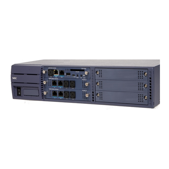
7. CHS2U-xx 19-inch KSU The CHS2U-xx KSU has six universal board slots for legacy line / trunk board (Single Line Telephone Interface, Digital Multi-line Terminal Interface, Central Office Trunk, ISDN PRI Interface, etc.), In-skin Application boards (In-skin UMS, In-Skin Router, etc.). It also houses BUS Interface board, Power Supply Unit (PSU) and Cooling FAN. -
Page 24: Floor Mounting The 19" Ksu
7.1 Floor Mounting the 19” KSU The CHS2U-xx controlling and expansion KSU can be mounted on the floor using the CHS BASE UNIT and the CHS2U JOINT BRACKET KIT. Fig7-1 CHS2U Floor Mounting Table 7-1 Hardware for Floor Mounting Installation Description B CODE Feature... -
Page 25: Stand Mounting The 19" Ksu
7.2 Stand Mounting the 19” KSU A single or multiple KSU can be stand mounted. Controlling KSU can be stand mounted using the CHS2U STAND KIT (K) and Expansion KSU can be stand mounted together using CHS2U STAND KIT (EXT). Upto total 3 KSUs can be stand mounted. -
Page 26: Wall Mounting The 19" Ksu
When wall mounting Controlling KSU, ensure the wall can support the weight of the KSU (25kg per system KSU ---- including boards, cords, power supply, etc.). The KSU is secured to the wall with a wall mount bracket. NEC recommends only one KSU per wall mount. Fig 7-3 Table 7-3 Hardware for Wall Mounting Installation... -
Page 27: Rack Mounting The 19" Ksu
7.4 Rack Mounting the 19” KSU A single or multiple KSU can be mounted in the IEC-standard 19 inch rack. Controlling and Expansion KSU can be racked mounted by stacking them horizontally. The 19” KSU requires two rack mount brackets per KSU for mounting. Fig 7-4-1 CHS2U Rack Mount Brackets (2 pcs/KIT) Fig7-4-2 Fig7-4-3... -
Page 28: Chs2U-Gw-Xx / Chs2U B-Xx / Chs2U E (9.5 Inch Ksu)
8. CHS2U-GW-xx / CHS2U B-xx / CHS2U E (9.5 inch KSU) The CHS2U-GW-xx / CHS2U-B-xx, 9.5 inch Chassis has three (Slot 1 for CPU) universal board slots for legacy line / trunk board (Single Line Telephone Interface, Digital Multi-line Terminal Interface, Central Office Trunk, ISDN PRI Interface, etc.), In-skin Application boards (In-skin UMS, In-Skin Router, etc.). -
Page 29: Wall Mounting The 9.5 Inch Ksu
8.1 Wall mounting the 9.5 inch KSU When wall mounting the KSU, ensure the wall can support the weight of the KSU (25 lbs per system KSU ---- including boards, cords, power supply, etc.). The KSU is secured to the wall with a supplied wall mount bracket. -
Page 30: Stand Mounting The 9.5 Inch Ksu
8.2 Stand mounting the 9.5 inch KSU CHS2U-GW-xx / CHS2U-B-xx, 9.5 inch KSU can be stand mounted using the bracket supplied for wall mount. This bracket is not for use with a combined Base (CHS2U B-xx) and Expansion (CHS2U E) chassis. A combined Base and Expansion chassis should only be rack or wall mounted. -
Page 31: Rack Mounting The 9.5 Inch Base And Expansion Chassis
8.3 Rack mounting the 9.5 inch Base and Expansion Chassis To rack mount the combined Base (CHS2U B-xx) and Expansion (CHS2U E) chassis, the IP3-RACK MOUNT BAR SET is required. Base and Expansion chassis must be installed vertically for proper air circulation. 1) Attach the metal rack mount brackets to each side of the chassis using the screws provided. - Page 32 2) Secure the (CHS2U B-xx) and (CHS2U E) chassis to the horizontal bars using two screws at each point. Fig 8-3-2 Attach (CHS2U B-xx) and (CHS2U E) Chassis to Rack Table 8-3 Hardware for 9.5 inch B+E Rack Mounting Installation Description B CODE Feature...
-
Page 33: Battery Type
9. Battery type Below table shows each Battery BOX, cable, and battery type with Supplier Product Name. Two batteries are used as one set. The same Manufacturer should be used for the set. Table 9 Battery BOX Configuration Battery Supplier Terminal Type of Battery BOX type Battery BOX... -
Page 34: Internal Battery Mounting Kit (19 Inch Ksu)
9.1 Internal Battery Mounting Kit (19 inch KSU) An internal battery source using two batteries can be installed using the CHS2U BATT MTG KIT (mounting kit) and CHS2U BATT CABLE INT (internal cabling). CHS2U BATT MTG KIT (Backup time = 10 Minutes/24 Terminals) Fig 9-1-1 Installing Battery Cable Fig 9-1-2 Installing Battery Tray into CHS2U KSU... -
Page 35: Attaching Chsgw Small Batt Box (9.5 Inch Ksu)
9.2 Attaching CHSGW SMALL BATT BOX (9.5 inch KSU) An optional CHSGW SMALL BATT BOX can be installed to provide external battery power to the 9.5 inch KSU during power failure. This CHSGW SMALL BATT BOX can power the system approximately 10 minutes. -
Page 36: Long Term Battery Box
9.3 Long Term Battery Box When CHS LARGE BATT BOX can be used both for 19 inch KSU and 9.5 inch KSU, there are two types of the external battery cable. Connections are shown below. The battery cables between CHS2U chassis and CHS BATT BOX are attached in the CHS LARGE BATT BOX. - Page 37 Fig 9-3-2 Inside View of External Battery Box...
-
Page 38: Voip Daughter Board (Voipdb)
10. VoIP daughter board (VoIPDB) There are 3 types of VoIPDBs, PZ-32IPLA, PZ-64IPLA and PZ-128IPLA. To select either PZ-32IPLA, PZ-64IPLA or PZ-128IPLA, a detailed traffic calculation is necessary. The following table shows the VoIPDB channels required in each VoIP connection. Table 10 VoIPDB Channels Required in Each VoIP Connection IP terminal IP terminal... -
Page 39: Vm Configuration
11. VM Configuration Following table shows VM/VRS feature configuration using PZ-VM21, CD-VM00 and suitable Application CF. Table 11 VM Configuration CF Product Base Country Type Language(Default) CF Size Function Name Port Config AZ English 2 Port AKS InMail AU Japanese 512MB Mail Chinese(Mandarin) -
Page 40: License
12. License When installing the system and activating operational features beyond default system ports/features available initially, several licenses are required. The following table shows license models available in SV8100. “✓ ” means these license are applied. “ON ” means these functions are always activated. “... - Page 41 Category Functions License Model BSSD VoiceMail VRS Channel LKS-VM-VRSxx-LIC ✓ ✓ (Embedd (*2) VM Channel LKS-VM-INMAILxx-LIC ✓ ✓ (*2) VRS/VM Multi-language LKS-VM-LANGUAGE ✓ ✓ ✓ ✓ -LIC VM Box users LKS-VM-USER1-LIC ✓ InMail Email Notification ON/OFF LK-VM-EMAIL-LIC ✓ InMail Email Client LK-VM-EMAIL Client ✓...
- Page 42 Category Functions License Model BSSD Assistant upgrade LK-DESKTOP SUITE- PC ✓ ✓ ✓ ✓ (SoftPhone to Assistant) ASSISTANTxx-LIC LKS-SP E Client-IP ✓ ✓ ✓ ✓ Softphone Client xx-LIC R2.5 LK-DT Client xx-LIC ✓ ✓ ✓ ✓ Desktop Client R2.5 LK-DT SP E Client-IP ✓...
-
Page 43: Limitation Without Memdb(Pz-Me50)
Category Functions License Model BSSD (*1) EU version of main s/w have 128 ports capability at default, if PZ-ME50-EU is installed full 128 ports will be available, if not installed port size will be limited to 64 ports. LK-SYS-256 PORT-LIC license will increase the system capacity from 128 ports to 256 ports. (*2) When PZ-ME50 is installed max16 ports of PZ-VM21 will be shared by combination of both VRS port and VM port, if PZ-ME50 is not installed max 8 ports will be shared. -
Page 44: Dsp Resources
14. DSP Resources CD-CP00-xx have 128 channel DSP sender both for basic and expand chassis, and 32 channel DSP resources (receivers) only for basic chassis. PZ-BS10 have 64 DSP resources (receivers) only for expand chassis. These DSP sender and resources channels are used for following purpose exclusively. Table 14-1 DSP Resource Mapping Basic Chassis Expand Chassis...