
Related Manuals for Casio 130CR


Summary of Contents for Casio 130CR
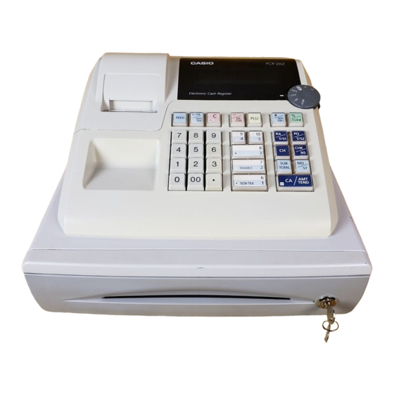
- Page 1 SERVICE MANUAL (without price) ELECTRONIC CASH REGISTER 130CR/PCR-262/CE-160 (EX-264) JAN. 2005 INDEX Ver.2 : Aug. 2009...
-
Page 2: Table Of Contents
CONTENTS 130CR/PCR-262/CE-160 Page 1. SPECIFICATIONS ..................1 2. MACHINE INTIALIZATION ................3 3. BLOCK DIAGRAM ..................4 4. DISASSEMBLY .................... 5 5. CIRCUIT EXPLANATION ................9 6. DIAGNOSTIC OPERATIONS ..............16 7. TROUBLESHOOTING ................20 8. IC DATA ..................... 21 9. -
Page 3: Specifications
1. SPECIFICATIONS 1-1. Electrical specifications 120 V 220 V 230 V 240 V • Power consumption In operation Max. 0.1 A 0.05 A 0.05 A 0.05 A Mangan Battery (UM-3 × 3 pcs) • Memory protection Back-up battery 1 year (25 °C) Back-up period Battery life Replace the battery every 1 years. - Page 4 1-5. Option List DEVICE NAME MODEL NOTE • Wet cover WT-80 • Roll paper P-5860 58 x 12 x 60D CAUTION Danger of explosion if battery is incorrectly replaced. Replace only with the same or equivalent type recommended by the manufacturer. Dispose of used batteries according to the manufacture’s instructions.
-
Page 5: Machine Intialization
5. Replace the printer paper and printer cover. REPLACE MEMORY PROTECTION BATTERIES AT LEAST ONCE EVERY YEAR. 2-2. To select the date format and monetary mode (130CR only) You can select the date format and the monetary mode after initialization depending on the requirements in your area. -
Page 6: Block Diagram
3. BLOCK DIAGRAM TRANSFORMER DRAWER TE-264-*** BATTERY WINDER UM-3(PZ) X3 MOTOR MODE SWITCH PRINTER E-264-1 M-42V KEY BOARD DISPLAY — 4 —... -
Page 7: Disassembly
4. DISASSEMBLY Removing the register 1. Remove the journal cover and then the WINDING PULLY and ROLL PAPER. 2. Remove the battery cover and then the battery. 3. Remove the two screws. Screws 4. Separate the main unit as shown below. 5. - Page 8 Removing the Main PCB and Display PCB 6. Remove the three connectors (CNKEY1, CNBAT1, CNPR1) and the four screws. 7. Remove the two hooks and then Main PCB. Connector (CNKEY1) Hook Connector (CNPR1) Connector (CNBAT1) Hook Screws 8. Remove the two hooks and then Display PCB. Hooks Removing the printer unit 9.
- Page 9 Disassembling the keyboard unit 10. Remove the FPC as well as the four screws, and then the keyboard unit. 11. Remove the two screws and then disassemble the keyboard unit. Hooks Screws Screws Chassis Common sheet Spacer — 7 —...
- Page 10 Disassembling the drawer 1. Pull the lever and remove the coin case and bill case. 2. Remove the three screws and then the top plate. Screws 3. Remove the three screws and the solenoid. Screws — 8 —...
-
Page 11: Circuit Explanation
5. CIRCUIT EXPLANATION 5-1. CPU (IC3: uPD780058BGC124-8BTA) 5-1-1. Pin Assignment 80 79 78 77 76 75 74 73 72 71 70 69 68 67 66 65 64 63 62 61 P15/ANI5 RESET P16/ANI6 P127/RTP7 P17/ANI7 P126/RTP6 P125/RTP5 P130/ANO0 P124/RTP4 P131/ANO1 P123/RTP3 P122/RTP2 REF1... - Page 12 5-1-2. Block Diagram TO0/P30 Port 0 P01 to P05 16-bit timer/ TI00/P00 event counter TI01/P01 Port 1 P10 to P17 TO1/P31 8-bit timer/ event counter 1 TI1/P33 Port 2 P20 to P27 TO2/P32 8-bit timer/ event counter 2 TI2/P34 Port 3 P30 to P37 Watchdog timer Port 4...
- Page 13 5-1-3. Pin Function (1) Port pins (1/2) Pin Name Function After Reset Alternate Function Input Port 0 Input only Input INTP0/TI00 7-bit I/O port Input/output can be specified in 1-bit Input INTP1/TI01 units. INTP2 If used as an input port, an on-chip INTP3 pull-up resistor can be connected by INTP4...
- Page 14 (1) Port pins (2/2) Pin Name Function After Reset Alternate Function P40 to P47 Port 4 Input AD0 to AD7 8-bit I/O port Input/output can be specified in 8-bit units. If used as an input port, an on-chip pull-up resistor can be connected by setting software.
- Page 15 (2) Non-port pins (1/2) Pin Name Function After Reset Alternate Function INTP0 External interrupt request inputs with specifiable Input P00/TI00 INTP1 valid edges (rising edge, falling edge, both rising and P01/TI01 INTP2 falling edges). INTP3 INTP4 INTP5 Serial interface serial data input Input P25/SB0 P70/RxD...
- Page 16 (2) Non-port pins (2/2) Pin Name Function After Reset Alternate Function AD0 to AD7 Lower address/data bus when expanding memory Input P40 to P47 externally A8 to A15 Output Higher address bus when expanding memory Input P50 to P57 externally Output Strobe signal output for read operation from external Input...
-
Page 17: Reset Circuit
5-2. Reset circuit/Printer circuit/Power circuit Reset circuit IC3:uPD780058BGC124-8BTA TRES 100K /RESET Vout ECQ-B1H103-KF 100u/10V S-80828CNY Printer circuit HE40TKYB221K CNWIN1 ERG-1SJ100 OUT1 OUT2 2P-SAN OUT3 CNPR1 LB1268 MAG- 330u/10V DSTC50TKYR103K MAG+ CM05RB03 MOT+ DSTC50TKYR103K ECQ-B1H103-KF MOT- C29 HE60TKYB222K 52011-0810 HE60TKYB222K HE60TKYB222K Power circuit 2SD2396 MTZJ4.7A... -
Page 18: Diagnostic Operations
6. DIAGNOSTIC OPERATION To start the diagnostic program ECR enters the diagnostic mode by the following operation. 1 Turn the mode key to PGM. 2 Input “99990000” and “ST(SUB TOTAL)”. Upon the above operation ECR prints the following and issues a receipt. * Note that the test mode will not boot if once a receipt has been issued in the REG/RF/X/Z mode. - Page 19 6-3. Displaying the Switch Condition Press the clear key, or change the status of switches to display the current conditions. [DISPLAY] Mode SW 1:PGM, 2:RF, 4:REG, 5:CAL, 6:X, 7:Z, 0:no contact FEED key 1:ON, 0:OFF No tax PAD (film) 1: tax (default) 0: no tax (cut) PAD2 1:SHORT...
- Page 20 6-4. Operations Bulk test Operation : ST (SUB TOTAL) All lit in the display, time and date setting, drawer open. • All lit (display) : 8 8 8 8 8 8 8 8 = ↑ (transaction) • Waits for key input •...
- Page 21 Battery test Operation : ST (SUB TOTAL) All the fonts are printed. US (Total of 14 digits) Other than US (Total of 12 digits) Blank line Time display test Operation : ST (SUB TOTAL) Time is displayed until the clear key is pressed or a power down occurs. Ending the test mode To leave the test mode, remove the battery (AUTO MAC).
-
Page 22: Troubleshooting
7. TROUBLESHOOTING 130CR Symptom/Problem Most common causes Solutions E01 appears on the display. Changing modes without Return mode switch to completing transaction. where it stops buzzing and press CA AMT TEND E94 appears on the display. Printer paper is jammed. -
Page 23: Ic Data
8. IC DATA 1. BA05CC0T (IC1) Vref Driver Pin No. Pin name Description Input Power Supply Output Power Supply 2. S-80828CNY (IC2) VEFR Bottom view * Parasitic diode 3. LB1268 (IC4) OUT3 OUT1 OUT2 TOP VIEW OUT1 OUT2 OUT3 6.8K 3.4K 6.8K PIN DESCRIPTIONS... -
Page 24: Pcb Layput
9. PCB LAYPUT — 22 —... -
Page 25: Circuit Diagram
10. CIRCUIT DIAGRAM MODEL : 130CR/PCR-262/CE-160 (EX-264) CONTENTS 1. MAIN BOARD ........................... 24 2. DISPLAY BOARD ........................25 3. MODE KEY ..........................26 — 23 —... - Page 26 S5 5 uPD780053GC / DSTC50TKYR103K S6 6 uPD780058BGC S7 7 RB441Q-40 1SR139-400 1SR139-400 7P-SDN TE12TKYB103K 4700u/25V 330u/25V AC IN 100u/10V 5298T TE-264-E1U/TE-264-E1D Model Board No. Name Drawing No. EX-264 E264-1 A MAIN BOARD RJE501400D203 CASIO COMPUTER CO.,LTD. — 24 —...
- Page 27 HDSP-521G HDSP-521G HDSP-521G HDSP-521G Model Board No. Name Drawing No. CASIO COMPUTER CO.,LTD. EX-264 E264-E2 A DISPLAY BOARD RJE501400D304 — 25 —...
- Page 28 MODE_KEY 52045-0845 Model Board No. Name Drawing No. CASIO COMPUTER CO.,LTD. EX-264 E264-E3 C MODE KEY RJE501400D405 — 26 —...
-
Page 29: Parts List
2. As for spare parts order and supply, refer to the “GUIDEBOOK for Spare Parts Supply”, published separately. 3. The numbers in item column corespond to the same numbers in drawing. 4. CASIO does not supply the spare parts without parts code. 5. Remarks Q'ty : Quantity used per unit... - Page 30 UPPER CASE — 28 —...
- Page 31 KEYBOARD 6 to — 29 —...
-
Page 32: 130Cr
130CR Q'ty Other Countries Price Item Code No. Parts Name Specification Rank Europe Germany Australia Plug Type Code Europe 1. MAIN PCB BLOCK & MAIN DISPLAY BLOCK 1018 5203 PCB ASSY/E264-1 RJE501349*002V01 1018 5245 PCB ASSY/E264-1 RJE501349*003V01 N IC3 1019 1510... -
Page 33: Button Block
130CR Q'ty Other Countries Price Item Code No. Parts Name Specification Rank Europe Germany Australia Plug Type Code Europe N CNKEY1 6221 4761 CONNECTOR 52045-2145 N CNDRW1 1013 6161 CONNECTOR IL-G-2P-S3T2-SA 3540 4871 CONNECTOR 52045-0445 N CNPR1 3500 1077 CONNECTOR... - Page 34 130CR Q'ty Other Countries Price Item Code No. Parts Name Specification Rank Europe Germany Australia Plug Type Code Europe AC/C PLATE/S 2E270 RJE500737-2 -/ERR.CORR PLATE/S 4E270 RJE500737-4 PLATE/S 5E270 RJE500737-5 PLATE/S 10E270 RJE500737-10 X/3/8 PLATE/L 16E270 RJE500738-16 CA/AMT TEND PLATE/L 4E270...
- Page 35 PCR262/CE160 Q'ty Price Item Code No. Parts Name Specification Rank Canada Code 1. MAIN PCB BLOCK & MAIN DISPLAY BLOCK 1018 5149 PCB ASSY/E264-1 RJE501349*001V01 N IC3 1019 1510 D780058BGC124-8BTA 2120 6253 LB1268 N IC1 1019 5663 BA05CC0T N IC5,6 2240 5365 TD62083AP 1009 4206...
- Page 36 PCR262/CE160 Q'ty Price Item Code No. Parts Name Specification Rank Canada Code N CNBAT1 1019 5662 CONNECTOR 5267-02A-X N CNKEY1 6221 4761 CONNECTOR 52045-2145 N CNDRW1 1013 6161 CONNECTOR IL-G-2P-S3T2-SA 3502 2492 CONNECTOR 2P-SAN N CNPR1 3500 1077 CONNECTOR 52011-0810 1007 9249 BUZZER PKM22EPT-2001-B0...
-
Page 37: Power Cord Block
PCR262/CE160 Q'ty Price Item Code No. Parts Name Specification Rank Canada Code FEED PLATE/S 1E270 RJE500737-1 AC/C PLATE/S 2E270 RJE500737-2 X/FOR/DATE TIME PLATE/S 30E270 RJE500737-30 -/ERR.CORR PLATE/S 4E270 RJE500737-4 PLATE/S 5E270 RJE500737-5 #/DEPT SHIFT PLATE/S 6E270 RJE500737-6 %/CLK# PLATE/S 7E270 RJE500737-7 RA/T/S1 PLATE/S 31E270... -
Page 38: Drawer (Dl-1329A)
5. DRAWER (DL-1329A) — 36 —... - Page 39 DL-1329A(S type) U.S.A. Price N Item Code No. Parts Name Specification Qt'y Rank code 10127601 CASE/MAIN RJE500670-001V01 10127602 PLATE/T.C ED21-16 RJE500672-001V01 55000878 ROLLER/DELRIN DR-19B2 10259120 LEVER ASSY/HOOK RJE502182*001V01 10127603 AXIS/HOOK LEVER ED21 RJE500674-001V01 10080393 SPRING/LOCK ED16 RJE500007-001V01 62466522 SPRING/PRESS ED14 E412137-1 62466529 RUBBER/ED14...
-
Page 40: Drawer (Dl-1841A)
6. DRAWER (DL-1841A) — 38 —... - Page 41 DL-1841A(S type) Germany, Europe, Other countries Price N Item Code No. Parts Name Specification Qt'y Rank code 1012 7601 CASE/MAIN RJE500670-001V01 1012 7602 PLATE/T.C ED21-16 RJE500672-001V01 5500 0878 ROLLER/DELRIN DR-19B2 10259120 LEVER ASSY/HOOK RJE502182*001V01 1012 7603 AXIS/HOOK LEVER ED21 RJE500674-001V01 1008 0393 SPRING/LOCK ED16 RJE500007-001V01...
-
Page 42: Drawer (Dl-2794A)
7. DRAWER (DL-2794A) 22 27 — 40 —... - Page 43 DL-2794A(M type) Europe, Other countries Item Code No. Parts Name Specification Qt'y Price Rank code 1. MAIN CASE BLOCK 1 10078897 CASE/MAIN E140494-1 2 55000619 ROLLER/DELRIN DR-19B1 3 10079066 NUT 6 ZMC-3 4 10078764 LEVER/HOOK E341286-1 5 10078754 AXIS/HOOK LEVER E341241-1 SCREW 3X8 ZMC-3...
-
Page 44: Drawer (Dl-2796A)
8. DRAWER (DL-2796A) 22 27 — 42 —... - Page 45 DL-2796A(M type) Canada Item Code No. Parts Name Specification Qt'y Price Rank code 1. MAIN CASE BLOCK 1 10078897 CASE/MAIN E140494-1 2 55000619 ROLLER/DELRIN DR-19B1 3 10079066 NUT 6 ZMC-3 4 10078764 LEVER/HOOK E341286-1 5 10078754 AXIS/HOOK LEVER E341241-1 SCREW 3X8 ZMC-3 6 10080393 SPRING/LOCK RJE500007-001...
- Page 46 Ver.1: Mar. 2005 Correction of pages 37 and 39 Ver.2 : Aug. 2009 • Correction of the PARTS LIST (P28, 30, 31, 32, 33, 34, 35, 37 and 39) CASIO COMPUTER CO.,LTD. Overseas Service Division 6-2, Hon-machi 1-Chome Shibuya-ku, Tokyo 151-8543, Japan...