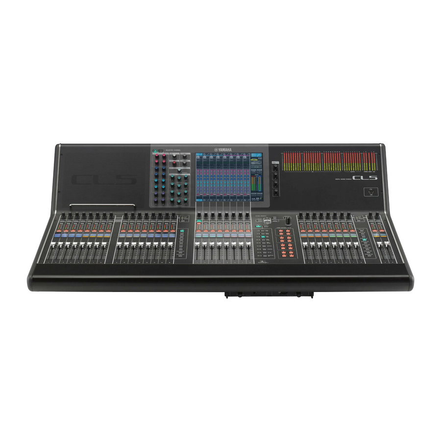
Yamaha CL5 Supplementary Manual
Digital mixing console
Hide thumbs
Also See for CL5:
- Reference manual (306 pages) ,
- Owner's manual (67 pages) ,
- Supplementary manual (26 pages)
Table of Contents
Advertisement
Quick Links
Advertisement
Table of Contents

Summary of Contents for Yamaha CL5
- Page 1 V2.0 Supplementary Manual This supplementary manual explains mainly the functions that have been added or changed in CL5/CL3/CL1 firmware V2.0. Use it in conjunction with the CL5/CL3/CL1 Owner’s Manual, Reference Manual, and V1.7 Supplementary Manual.
-
Page 2: Table Of Contents
Contents Contents SELECTED CHANNEL section ............Added fader function....................Added insert function ....................Input channels ................Added gain function ....................Grouping and linking ............... DCA Roll-out function....................Added DCA output channels ................... Added mute group function ..................Added channel link function ..................Added channel job function.................. -
Page 3: Selected Channel Section
SELECTED CHANNEL section SELECTED CHANNEL section Added insert function You can now insert two devices into a single channel or bus. Added fader function ■ Setting inserts The TOUCH AND TURN function assigned to one of the USER DEFINED knobs enables you to Use a bank select key or [SEL] key to select the channel or bus to which you want control the fader in the FADER field of the SELECTED CHANNEL VIEW screen. -
Page 4: Input Channels
MIX1-24/ If GC (Gain Compensation) is enabled, you can link the digital gain to the analog gain operation. CH1-16 CH17-32 CH33-48 (CL5 and MATRIX1-8 (CL5 only) ST/MONO While you are controlling the analog gain, the Gain Compensation function enables you to modify the CL3 only) level on your own console without affecting the level of other consoles. -
Page 5: Grouping And Linking
Grouping and linking ■ Setting the DCA Roll-out function Grouping and linking In the Function Access Area, press the CH JOB button. DCA Roll-out function DCA GROUP button You can now access all of the channels assigned to a DCA group simultaneously through the fader banks. -
Page 6: Added Dca Output Channels
Grouping and linking Added DCA output channels You can now assign the Stereo/Mono bus master, Mix bus master, and Matrix bus master channels to a DCA group. DCA groups were formerly used exclusively for input channels. However, with this new feature, you can use the DCA groups for output master channels, which enables for more flexible simultaneous controls. -
Page 7: Added Mute Group Function
Grouping and linking Added mute group function The MIX MINUS popup window will open. You can now unmute a muted channel in the mute group temporarily. If the master button is turned on for the mute group to which the target channel belongs, press the [ON] key for that channel to temporarily unmute the channel. -
Page 8: Scene Memory
Scene memory Scene memory • R (READ ONLY) symbol Not only will the scene be protected, it will also not be overwritten by any file loaded from a USB flash drive. You can only apply the protect setting to scenes with consecutive scene numbers starting with scene #001. -
Page 9: Graphic Eq, Effects, And Premium Rack
Graphic EQ, Effects, and Premium Rack Graphic EQ, Effects, and Premium Rack Enhanced Graphic EQ functions Now you can compare the sound before and after gain adjustments during GEQ operations. In the GEQ popup window, use the buttons in the FADER ASSIGN field to specify the frequency band you want to control. -
Page 10: User Settings
You can now view the gain reduction meters for Dynamics 1 and 2, as well as other information, on the The current CL version supports Yamaha Console Extension V2. Due to this support, you can now edit channel name display. -
Page 11: Other Functions
Function PARAMETER 1 PARAMETER 2 DEFINED keys DIRECT OUT LEVEL SELECTED CH, CL5: CH1–CH72, CL3: CH1–CH64, LEVEL CL1: CH1–CH48 New functions have been added that can be assigned to the USER DEFINED keys. OUTPUT LEVEL LEVEL MIX1–MIX24, MTRX1–MTRX8, ST L, ST R, MONO (C) - Page 12 Yamaha Pro Audio Global Web Site http://www.yamahaproaudio.com/ Yamaha Manual Library http://www.yamaha.co.jp/manual/ C.S.G., PA Development Division © 2014 Yamaha Corporation Published 06/2014 IP-A0...


