Napoleon BGD40-P Installation And Operation Instruction Manual
Natural and propane gas
Hide thumbs
Also See for BGD40-P:
- Installation and operating instructions manual (104 pages) ,
- Installation and operation instructions manual (36 pages) ,
- Installation and operating instructions manual (104 pages)
Table of Contents
Advertisement
Quick Links
Advertisement
Table of Contents

Related Manuals for Napoleon BGD40-P


Summary of Contents for Napoleon BGD40-P
- Page 1 W415-0299 / J / 04.14.08 $10.00 W415-0299 / J / 04.14.08...
-
Page 2: Table Of Contents
TABLE of CONTENTS Adjustable Firestop Pg 3-5 INTRODUCTION Vertical Venting Installation Warranty Flexible Vent Components General Instructions Fireplace Vent Connection General Information Rigid Vent Components Care of Glass & Plated Parts Gas Supply Connection Dimensions 22-25 FINISHING 6-13 VENTING Mantel Installation and Enclosures Vent Lengths Heat shield stand-off Minimum Air Terminal Location Clearances... - Page 3 After the fi rst year, NAPOLEON® will not be responsible for installation, labour or any other costs or expenses related to the reinstallation of a warranted part, and such expenses are not covered by this warranty.
-
Page 4: Introduction
INTRODUCTION the rate of 4% for each additional 1,000ft. Maximum output for natural GENERAL INSTRUCTIONS gas is 20,400 BTU/hr at an effi ciency of 68% with the fan on. THIS GAS FIREPLACE SHOULD BE INSTALLED AND SERVICED Minimum inlet gas supply pressure is 4.5" water column for natural BY A QUALIFIED INSTALLER to conform with local codes. -
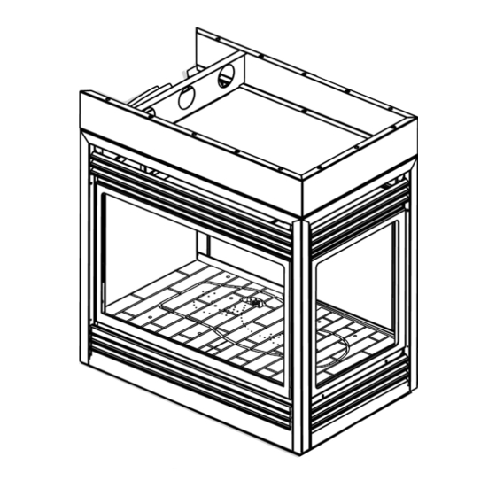
Page 5: Dimensions
DIMENSIONS PENINSULA FIGURE 1a OPEN-END FIGURE 1b SEE-THRU FIGURE 1c W415-0299 / J / 04.14.08... -
Page 6: Venting
VENTING VENTING LENGTHS Use only Wolf Steel or Simpson Dura-Vent Model DV-GS, For optimum fl ame appearance and fi replace performance, Selkirk Direct Temp or American Metal Amerivent venting keep the vent length and number of elbows to a minimum. components. -
Page 7: Minimum Air Terminal Location Clearances
MINIMUM AIR TERMINAL LOCATION CLEARANCES FIGURE 2 W415-0299 / J / 04.14.08... -
Page 8: Venting Application Flowchart
VENTING APPLICATION FLOWCHART VERTICAL HORIZONTAL TERMINATION TERMINATION V e r t i c a l Vertical rise Vertical rise V e r t i c a l rise is equal is less than is less than rise is equal to or great- horizontal horizontal to or great-... -
Page 9: Typical Minimum And Maximum Vent Lengths
TYPICAL MINIMUM AND MAXIMUM VENT LENGTHS FIGURE 3a When terminating vertically, the vertical rise is a minimum 34" and a maximum 40 feet above the fi replace. FIGURE 3b. When venting, the horizontal run must be kept to a maximum of 20 feet. - Page 10 DEFINITIONS ELBOW VENT LENGTH VALUES for the following symbols used in the venting calculations Feet inches and examples are: 1° 0.03 > - greater than 15° 0.45 > - equal to or greater than 30° 11.0 < - less than 45°* 1.35 16.0...
- Page 11 HORIZONTAL TERMINATION Example 2: When (H ) > (V 90° Simple venting confi guration (only one 45º and 90° elbow) FIGURE 8 FIGURE 7 See graph to determine the required 45° vertical rise V for the required hori- zontal run H 90°...
- Page 12 VERTICAL TERMINATION When (H ) < (V Example 3: Simple venting confi gurations FIGURE 9 FIGURE 10 90° 90° 45° 45° 90° See graph to determine the required vertical rise V for the required horizontal run H = 5 ft = 10 ft = 5 + 10 = 15 ft = 3 ft...
- Page 13 VERTICAL TERMINATION When (H ) > (V = 1 ft Simple venting confi gurations = 1.5 ft = 1 + 1.5 = 2.5 ft FIGURE 11 = 6 ft = 2 ft = 6 + 2 = 8 ft = .03(one 45º elbow + three 90º elbows - 135º) = .03(45 + 90 + 90 + 90 - 135) = 5.4 ft = 8 + 5.4 = 13.4 ft = 13.4 + 2.5 = 15.9 ft...
-
Page 14: Peninsula Installation Procedure
PENINSULA INSTALLATION PROCEDURE VENTING COUNTER TOP / BAR INSTALLATION Refer to pages 6-13. All venting must have a minimum clear- When fi nishing the fi replace, combustible material may rest ance of 2" to combustible material on the top and 1" to the directly on of the top extension. -
Page 15: Brick Panel Installation
BRICK PANEL INSTALLATION FACING Combustible materials may be installed fl ush with the front of Install the base panels as illustrated in steps 1-4 . The side the fi replace but must not cover any of the black face-areas panel sits under the bracket tab. Holding the side panel in of the fi... -
Page 16: Open End Installation Procedure
OPEN-END INSTALLATION PROCEDURE FIGURE 22 VENTING Refer to pages 6-13. All venting must have a minimum clear- ance of 2" to combustible material on the top and 1" on the RETAINER sides and bottom. FRAMING See Page 18 for additional framing dimensions. NOTE: In order to avoid the possibility of exposed insula- tion or vapor barrier coming in contact with the fi... -
Page 17: See-Thru Installation Procedure
SEE-THROUGH INSTALLATION PROCEDURE VENTING FACING Refer to pages 6-13. All venting must have a minimum clear- Combustible materials may be installed fl ush with the front of ance of 2" to combustible material on the top and 1" to the the fi... -
Page 18: Vent Framing Dimensions
MINIMUM VENT FRAMING DIMENSIONS There must be a minimum of 2" clearance to combustible ma- terial on the top and 2" to the sides and bottom when framing around all venting options. See pages 10-13. FIGURE 27a FIGURE 27b Horizontal Vent Off Fireplace Vertical Vent Off Fireplace A = 43"... -
Page 19: Wall And Ceiling Protection
INSTALLATION WALL AND CEILING PROTECTION HORIZONTAL VENT SECTIONS: A minimum clearance VERTICAL INSTALLATION of 1" at the bottom and sides and 2" at the top of the vent pipe on all horizontal runs to combustibles is required. Use This application occurs when venting through a roof. Instal- fi... - Page 20 USING FLEXIBLE VENT COMPONENTS For optimum performance, it is recommended that horizon- WARNING tal runs have a minimum ¼" rise per foot . All inner exhaust and outer intake vent pipe joints may be sealed using either ELBOW Do not allow the inside liner Red RTV high temp silicone sealant or Black high temp Mill to bunch up on horizontal or Pac with the exception of the fireplace exhaust flue collar...
-
Page 21: Fireplace Vent Connection
6. Aligning the seams of the FIREPLACE VENT CONNECTION terminal and air terminal connector, 1. Install the 5" diameter fl ex pipe place the terminal over the air to the fi replace. Secure with 3 FIGURE 41 terminal connector making sure screws and fl... -
Page 22: Finishing
OPTIONAL WALL SWITCH INSTALLATION For ease of accessibility, an optional remote wall switch may be installed in a WIRE SIZE LENGTH convenient location. A 20ft length of millivolt wire is connected to the gas valve 14 Gauge 100 Feet and wall switch. However, if a greater length is required route 2-strand (solid core) millivolt wire through the electrical hole located at the bottom left side of 16 Gauge 60 Feet... -
Page 23: Log Placement
LOG PLACEMENT PHAZER logs, glowing and charcoal embers, exclusive to Wolf Steel Ltd. fi replaces, provide a unique and realistic glowing effect that is different in every installation. Take the time to carefully position the embers for a maximum glowing effect. -
Page 24: Logo Placement
DOOR INSTALLATION GLOWING EMBERS Tear the embers into small pieces and place on the ported DOOR OPENING AND CLOSING: The upper louvres must be area of the burner. Care should be taken to shred the embers removed to allow the door to be opened or closed. To access into thin, small irregular pieces as only the exposed edges the lower door latch, open the valve control door. -
Page 25: End Door Installation
END DOOR INSTALLATION Ensure that the door is properly STEEL LIP clipped onto the DOOR steel lip to pre- vent overheating, glass breaka ge and / or discolora- tion of the upper trim. FIGURE 53 To install the door(s), hook it over the steel lip located above the door opening. -
Page 26: Optional Blower Installation
OPTIONAL BLOWER INSTALLATION Remove the "Z" shaped WARNING mounting bracket secured to the burner, by the pilot. INSTALLATION TO BE DONE BY A QUALIFIED IN- Remove the thermodisc from STALLER and must be electrically connected and ground- the bracket supplied in the ed in accordance with local codes. -
Page 27: Operation / Maintenance
OPERATION / MAINTENANCE When lit for the fi rst time, the fi replace will emit a slight odour After extended periods of non-operation such as following a for a few hours. This is a normal temporary condition caused vacation or a warm weather season, the fi replace may emit a by the curing of the logs and the "burn-in"... -
Page 28: Adjustments
ADJUSTMENTS PILOT BURNER ADJUSTMENT RESTRICTING VERTICAL VENTS Adjust the pilot screw to provide properly sized fl ame. Turn Vertical installations may display a very active fl ame. If this in a clockwise direction to reduce the gas fl ow. appearance is not desirable, the vent exit must be restricted using the optional restrictor vent kit, RP40-KT. -
Page 29: Replacements
W562-0009 DOOR GASKET (100") W455-0067 PROPANE GAS PILOT INJECTOR W010-0454 GLASS W/ GASKET W660-0005 BURNER ON/OFF SWITCH W010-1778 FIRESTOP W680-0004 THERMOPILE W385-0245 NAPOLEON® LOGO GL-657 BGD40 LOGSET W680-0005 THERMOCOUPLE W135-0284 LOG#1 W240-0006 ELECTRODE / WIRE W135-0285 LOG#2 W357-0001 PIEZO IGNITER... - Page 30 W415-0299 / J / 04.14.08...
-
Page 31: Accessories
ACCESSORIES 15 DOISS-1 DIAMOND ORNAMENTAL INSET - BRUSHED STAINLESS STEEL # PART No. DESCRIPTION 16 EDOIG-1 END DIAMOND ORNAMENTAL INSET - GOLD PLATED W690-0001 MILLIVOLT THERMOSTAT 16 EDOIKG-1 END DIAMOND ORNAMENTAL INSET - BLACK GOLD PLATED GD501 HEAT GUARD 16 EDOIBC-1 END DIAMOND ORNAMENTAL INSET - BRUSHED COPPER PLATED W573-0007... -
Page 32: Trouble Shooting Guide
TROUBLE SHOOTING GUIDE EFORE ATTEMPTING TO TROUBLESHOOT PURGE YOUR UNIT AND INITIALLY LIGHT THE PILOT AND THE MAIN BURNER WITH THE GLASS DOOR OPEN SYMPTOM PROBLEM TEST SOLUTION Main burner fl ame is a blue, Blockage in vent. - Remove blockage. In really cold conditions, ice buildup may occur lazy, transparent fl... - Page 33 SYMPTOM PROBLEM TEST SOLUTION Pilot will not light. No spark at pilot burner - Check if pilot can be lit by a match - Check that the wire is connected to the push button igniter. - Check if the push button igniter needs tightening. - Replace the wire if the wire insulation is broken or frayed.
- Page 34 W415-0299 / J / 04.14.08...
-
Page 35: Notes
NOTES W415-0299 / J / 04.14.08... - Page 36 NOTES W415-0299 / J / 04.14.08...