Table of Contents
Advertisement
Advertisement
Table of Contents

Related Manuals for Honda Modular Vehicle Communication Interface


Summary of Contents for Honda Modular Vehicle Communication Interface
- Page 1 Modular Vehicle Communication Interface (MVCI) User Guide...
- Page 2 This equipment operates on a secondary basis and, consequently, must accept harmful interference, including from stations of the same kind, and may not cause harmful interference to systems operating on a primary basis. © 2012 Service Solutions US LLC. All rights reserved. Contributions by American Honda Motor Co., Inc. 2013...
-
Page 3: Table Of Contents
Software Version ......36 Honda Diagnostic System (HDS) Setup ..13 Hardware Test . -
Page 4: Safety Precautions
Safety Precautions When an engine is running, keep the service area WELL VENTILATED, or attach a building exhaust removal system to the engine exhaust system. Engines produce carbon monoxide, an odorless, poisonous gas that causes slower reaction time and can lead to serious personal injury or loss of life. •... -
Page 5: General Information
General Information The BOSCH Modular Vehicle Communications Interface (MVCI) is an interface box used to connect to a vehicle’s data link connector (DLC). The MVCI is used to read information from a vehicle’s electronic control units, and send this information to a PC application. The MVCI communicates with the PC through a USB, Ethernet, or an SD wireless card. -
Page 6: Cables And Cable Connections
Cables and Cable Connections To avoid damaging the MVCI, the cards, or the cables, use the following information to help when attaching cables or connectors to the MVCI, or plugging in the SD wireless or the SD memory cards: NOTE: Do not remove the SD card unless a problem has occurred (see SD Card Removal/Installation for more information). -
Page 7: Sd Card Removal/Installation
SD Card Removal/Installation NOTE: Do not remove the SD memory card or the SD wireless card unless a problem has occurred. If you need to remove the SD card or the SD wireless card, do this: 1. Lift the top port cover. 2. -
Page 8: Mvci Component Descriptions
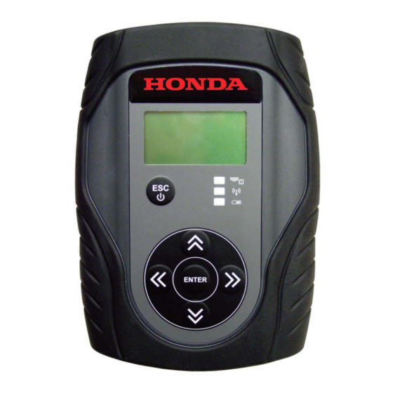
MVCI Component Descriptions... -
Page 10: Mvci Screen Icon Descriptions
MVCI Screen Icon Descriptions NOTE: Screens shown in this manual may vary in appearance due to the product software version at the time of shipment. The LCD screen is divided into two parts: the title bar, and the body. The title bar is divided into three parts: •... -
Page 11: Mvci Led Descriptions
MVCI LED Descriptions MVCI Software Installation MVCI Application Installation Install the Honda Diagnostic System (HDS) software according to the Installation Instructions for Honda Diagnostic System (HDS) PC Software found on ISIS under General Publications > Tool Information. NOTE: • The MVCI does not come with a CD. The software and updates are included in the HDS software image. -
Page 12: Network Connections Overview
Network Connections Overview There are three possible network connections: Ethernet, Wireless, and USB. Additionally, the MVCI can act as a DHCP server for any of these connections. • Ethernet Connection – The Ethernet driver automatically communicates with the MVCI if the MVCI’s external power source is plugged in and the MVCI is connected to the PC with an Ethernet cable. -
Page 13: Honda Diagnostic System (Hds) Setup
2. On the HDS Welcome screen, click the F12 tab. NOTE: Make sure the latest version of HDS software is installed. Check the latest version by logging into in.honda.com and selecting SERVICE>Service Bay>Diagnostic Tools Software Version. 3. On the Set-up Details screen, check for HDS software version. -
Page 14: Hds Mvci Firmware Update
HDS MVCI Firmware Update The MVCI software can be updated automatically or manually. If the MVCI does not have the latest software installed, the HDS automatically takes you to the MVCI reprogramming screen. For more information about automatic updating of the MVCI firmware, see Automatic Firmware Updates. To manually start the MVCI reprogramming, click the Program the MVCI button on the HDS Welcome screen, and see Manual Firmware Updates. - Page 15 3. Wait for the MVCI firmware update to start. 4. The MVCI automatically reboots. Follow the directions on the HDS screen. Do not disconnect the external power source or disconnect the MVCI from the PC. After the MVCI reboots, it displays the following messages to indicate which files are being updated: After the MVCI updates its firmware, the MVCI restarts and goes through its normal boot-up sequence.
- Page 16 5. When the MVCI firmware update is done, the screen below is displayed on the HDS. Press Enter on your keyboard or click the green check mark in the lower right corner to start the CM Update. The following update screen displays. MVCI and CM updates are complete! NOTE: The update sequence varies by the software content.
-
Page 17: Connecting The Mvci To The Vehicle
Connecting the MVCI to the Vehicle 1. Connect the data link connector (DLC) cable to the MVCI and to the DLC on the vehicle. 2. When you plug the MVCI into the vehicle’s DLC and turn the ignition switch to ON (II), the MVCI automatically boots up. -
Page 18: User Config - Explanations, Set-Up, And Customizing Settings
User Config – Explanations, Set-up, and Customizing Settings Anytime the MVCI receives power and boots up, the message on the Host Status screen is Waiting for User Input… Press Enter to Config. Under the User Config menu, you find the following choices. Refer to the applicable page for more detailed information explaining the functions, proper tool setup, and user customization: Switch Wireless (pg. -
Page 19: Switch Wireless
3. Wait for the MVCI to display the vehicle’s battery voltage. If the vehicle battery is below 12.1V, check the vehicle’s battery using a Honda-approved battery diagnostic tool like the ED-18 or the GR8. NOTE: The voltage shown is not accurate if the MVCI is plugged into the external power adapter. -
Page 20: Mvci System Setup
MVCI System Setup From the User Config menu, select MVCI Setup, then press ENTER. These options are available: • Clock • Contrast Control • Font Size • Wireless • SDMEM Format • Factory Defaults Clock If you want to change the time, date and date format of the MVCI, select View and Set, then press ENTER. To change the Calendar Data format, highlight Format, then press ENTER. -
Page 21: Contrast Control
Contrast Control To change the MVCI screen contrast (brightness), select View & Set under Contrast Control, then press ENTER. Use the left/right buttons to change the contrast percentage. Press ENTER to save the changes or press ESC to cancel. Font Size The MVCI can display a large font or a small font. -
Page 22: Wireless
Wireless This option allows you to enable or disable the wireless feature. NOTE: For U.S. users, keep the MVCI factory default setting Enable. To change the wireless option, select Enable under Wireless, then press ENTER. Highlight the desired option, then press ENTER to save the changes, or press ESC to cancel. SDMEM Format This feature allows you to erase and reformat the SD memory card installed to the MVCI. -
Page 23: User Customize
User Customize From the User Config menu, select User Customize, then press ENTER. The following options are available: • Language • Destination • Beep Menu Language The MVCI supports several languages. U.S. users should use only American English (default) because if you have a problem during updating and need to call the tools help line, English is currently the only supported language. -
Page 24: Beep Menu
Beep Menu There are three types of audio notifications (beeps) that you can configure in the Beep Menu. When you are using the MVCI CM Update, keep these beep notifications enabled: • Key Beep – The MVCI beeps when a button is pressed. •... -
Page 25: Cm Update Mode
CM Update Mode The MVCI is designed to update reprogrammable control modules. Before you begin reprogramming, make sure the MVCI is properly set up. After the MVCI is set up, you do not have to change the settings. These options are available: •... - Page 26 To check the CMU firmware version, do this: 1. From the CM Update Mode menu, select Setting 2, then press ENTER. 2. Select Check Version, then press ENTER. 3. Record the MVCI CM firmware version that appears on the display. Press ESC to exit.
-
Page 27: Network Setup
Network Setup Many of these options are used to set up a wireless network for your MVCI. Refer to Wireless Network Setup on page 30 for instructions on setting up your MVCI For most installations, the factory default settings should be used. The following setup information is included if you need a unique setup because of your PC configuration: •... -
Page 28: Usb Device
4. To save your changes, scroll down to the Network Service option, then press ENTER. USB Device 1. To change the USB device network settings, select USB Device under Network Setup, then press ENTER. 2. To change the IP address, highlight the IP address, then press ENTER. Use the up/down buttons to change the number and the left/right buttons to move between the components of the IP address. -
Page 29: Dhcp Server
DHCP Server The DHCP server setting controls whether the MVCI will act as a DHCP server for Ethernet, USB and wireless connections. 1. To change the DHCP server setting, select DHCP Server, then press ENTER. 2. The display shows the current setting of the DHCP server. To enable/disable the DHCP server, highlight the current status, then press ENTER. -
Page 30: Wireless Network Setup
Wireless Network Setup Introduction There are two ways to connect an HDS PC to the MVCI wirelessly: Infrastructure mode and adhoc (peer-to-peer) mode. When using Infrastructure mode, both the HDS PC and MVCI connect to a common wireless network that has access to the Internet. -
Page 31: Connecting Your Hds Pc Wirelessly
Connecting your HDS PC Wirelessly Select your operating system below: Windows XP (1), Windows Vista (2) or Windows 7 (3) 1. Windows XP a. Right-click on the Wireless Network Connection icon or open the WiFi connection utility located in the taskbar and select View Available Wireless Networks. - Page 32 2. Windows Vista a. Right-click the WiFi icon in the taskbar and select Connect to a network. b. Find and select the network that the MVCI was just configured for. Then click Connect. c. Once connected, the Connect to a network window can be closed.
-
Page 33: Connect To The Desired Mvci
3. Windows 7 Click on the WiFi icon located in the taskbar and select the network that was just configured on the MVCI. Then click Connect. Connect to the Desired MVCI • Double-click on the MVCI Wireless Connection Manager icon located on the desktop. •... -
Page 34: Mvci Status
MVCI Status From the User Config menu, select MVCI Status, then press ENTER. These status options are available: • SDIO-1 • SDIO-2 • Battery Charger • Host Status SDIO-1 The SDIO-1 slot has the SD memory card inserted. It holds all the calibration files needed for updating control modules/units. -
Page 35: Sdio-2
SDIO-2 The SDIO-2 slot has the MVCI wireless card inserted. It allows the MVCI to communicate on a wireless network. NOTE: Do not remove the MVCI wireless card unless a problem has occurred. To view the status of the SDIO-2 slot, select View Status, then press ENTER. The status screens appear. -
Page 36: Software Version
Software Version From the User Config menu, select Software Version, then press ENTER. The MVCI displays the software versions. NOTE: These screens are examples only. Actual data will vary. Hardware Test The MVCI includes several hardware tests that can check to make sure your MVCI is operating properly. From the User Config menu, select Hardware Test, then press ENTER. -
Page 37: Led Test
LED Test Select LED Test, then press ENTER. This test turns on the three LEDs for 3 seconds. LCD Test This test checks the LCD function by turning on all the pixels, showing two patterns, then turning off all the pixels. You can exit the LCD Test by pressing ESC. -
Page 38: Keypad Test
Keypad Test This test checks the up, down, left, right, and ENTER buttons. It does not check the ESC button, which is needed to exit the test. Select Keypad Test, then press ENTER. Check the five buttons. When you press each button, the applicable LCD should briefly light on the screen. Serial Number The serial number is printed on the back of the battery cover. -
Page 39: Device Loopback Test
Device Loopback Test This test checks the MVCI’s communication lines and analog circuits. 1. Make sure the MVCI is not connected to a vehicle. Select Device Loopback Test, then press ENTER. 2. A warning screen directing you to remove the DLC cable from the MVCI appears. Remove the cable, then press ENTER to start the test, or press ESC to exit. -
Page 40: Auxiliary Pc Applications
Auxiliary PC Applications These two additional auxiliary PC applications are included in the HDS software image: • MVCI Wireless Connection Manager • MVCI WiFi Setup Wizard MVCI Wireless Connection Manager Use this application to select the MVCI you want to connect to wirelessly. For more information, refer to the Wireless Network Setup section. -
Page 41: Mvci Wifi Setup Wizard
MVCI WiFi Setup Wizard Use this application to setup wireless profiles for the MVCI. Both adhoc and infrastructure profiles can be set up. Profiles are saved within the application for future use. NOTE: Information on wireless setup in general is beyond the scope of this document. Please contact your network administrator. -
Page 42: Updating Control Modules/Units
You will be prompted to update the MVCI when you use it with HDS. Control modules are updated under these conditions: • When directed by an official Honda service communication (service bulletin, product update, etc.) • When replacing a control module/unit. -
Page 43: Setting Up The Mvci For Updating
Setting Up the MVCI for Updating Refer to the User Config – Explanations, Set-up, and Customizing Settings to properly set up your MVCI. Make sure you use the recommended settings under CM Update Mode to avoid problems updating control modules. Instructions for Updating Control Modules/Units 1. - Page 44 7. After the MVCI finishes its search, a list of reprogrammable systems appears on the System Selections screen. Select the system to reprogram. Press ENTER to continue, or press ESC to exit. 8. The MVCI displays the Current Program ID, the System, and the latest Program ID. Press ENTER to continue or press ESC to exit.
- Page 45 NOTE: • Make sure the ignition is ON • Do not turn the MVCI off. • Do not disconnect the MVCI from the vehicle’s DLC. 12. If an error occurs during updating, leave the ignition ON, and go to Troubleshooting (Updating Errors). Press ENTER to display the error code.
-
Page 46: Updating With The Repeated Mode
Updating with the Repeated Mode If you need to update the same model vehicle, you can save time by selecting Repeated mode at the end of the update. This allows you to repeat the same system update on several vehicles without having to redo the setup. To update multiple vehicles, do this: 1. - Page 47 4. After you connect the DLC to the next vehicle, the following screen appears, telling you that the Repeated mode is turned on. Press ENTER to continue or press ESC to exit the repeated mode. NOTE: If the screen below appears when you turn on the MVCI, the previous user turned on the Repeated mode. Make sure you press ESC and start the reprogramming procedure again.
- Page 48 NOTE: • Make sure the ignition is ON • Do not turn the MVCI off. • Do not disconnect the MVCI from the vehicle’s DLC. 12. If an error occurs during updating, leave the ignition ON, and go to Troubleshooting (Updating Errors). Press ENTER to display the error code.
-
Page 49: Cm Update Troubleshooting
CM Update Troubleshooting Updating Errors Whenever the MVCI detects an error with the vehicle’s control module/unit update, a caution message appears on the MVCI. This is often followed by an error code to help you troubleshoot the problem. 1. If you see a caution message on the MVCI, leave the ignition ON. Press ENTER to show the error code. NOTE: •... -
Page 50: Display Error
Display Error The MVCI saves the last error code that it sets. You can view the error and confirm it by using the Display Error menu. 1. From the CM Update Mode menu, select Display Error, then press ENTER. 2. The MVCI usually lists the error code and a brief description of the problem. •... -
Page 51: Error Codes
Error Code Table Below is a list of error codes that can be displayed on the MVCI. Refer to the applicable code, and its description and possible solutions, for help. -
Page 55: Error Messages
Error Messages Below is a list of error messages that can be displayed on the MVCI. Refer to the applicable message, and its description and possible solutions, for help. -
Page 57: Battery Warning Messages
The MVCI has a built-in power management function. When the MVCI is connected to the vehicle’s DLC, the MVCI uses the vehicle’s battery to power itself. It also shows the vehicle battery’s state-of-charge, although, this information is for reference only. To check the vehicle’s battery, use a Honda-approved battery diagnostic tool like the ED-18 or the GR8. -
Page 58: Frequently Asked Questions
Frequently Asked Questions Is it possible to use the MVCI with the PC CM Update application, as with the HIM or GNA600? No. The MVCI is not compatible with the PC CM Update application. The MVCI can be used as a standalone device to reprogram control modules. - Page 59 Why does the battery icon on the Host Status screen have an ‘X’ in it? The batteries in the MVCI are not installed or they are installed incorrectly, or they are defective. Why does the battery icon on the Host Status screen have a ‘ZZ’ in it? Battery charging stops when the MVCI’s internal temperature rises above 140°F (60°C).
-
Page 60: Specifications
Specifications... - Page 61 BOSCH Service Solutions LLC Limited Warranty Honda and Acura Dealerships This Warranty is expressly limited to original retail buyers (“User”) of the BOSCH MVCI Tool (“Units”). Limited Warranty BOSCH Automotive Service Solutions and it’s authorized Repair Center(s) (referred to as "BOSCH") will repair this product with new or rebuilt parts, in the event of a defect in materials or workmanship.
- Page 62 BOSCH shall not be liable for loss of data or other incidental or consequential damages resulting from the use of this product, or arising out of any breach of this warranty. All express and implied warranties, including the warranties of satisfactory quality and fitness for a particular purpose are limited to the applicable warranty period set forth above.
-
Page 63: Warranty
Warranty and Service for Honda MVCI (P/N HON-3828-HR-AFT) Independent Repair Facilities Except as otherwise provided in this warranty; BOSCH Service Solutions Products are warranted against defects in materials and workmanship for three (3) years (36 months) from the date of shipment. BOSCH Service Solutions manufactured cables are warranted against defects in materials and workmanship for twelve (12) months from the date of shipment. - Page 64 • Modification or service by anyone other than BOSCH or its approved Service Providers. • Products whose serial number has been removed making the unit warranty condition impossible to clearly determine. BOSCH shall not be liable for loss of data or other incidental or consequential damages resulting from the use of this product, or arising out of any breach of this warranty.