Bosch ICP-EZM2 System Reference Manual
Easy series control panel
Hide thumbs
Also See for ICP-EZM2:
- Installer's manual (80 pages) ,
- System reference manual (126 pages) ,
- Quick start manual (24 pages)
Table of Contents
Advertisement
Quick Links
Download this manual
See also:
System Reference Manual
Advertisement
Table of Contents

Related Manuals for Bosch ICP-EZM2


Summary of Contents for Bosch ICP-EZM2
- Page 1 Easy Series Control Panel ICP-EZM2 System Reference Guide...
-
Page 3: Table Of Contents
Add a device 3.6.3 Replace a device 3.6.4 Delete a device Configure Wireless Devices from RPS Configure the B426 Programming Access Options System Access by Phone 4.2.1 RPS Connection Methods Bosch Security Systems, Inc. System Reference Guide 2014.09 | 01 | F.01U.306.221... - Page 4 8.7.3 Low battery 8.7.4 Wall Tamper Tab 8.7.5 Maintenance RADION TriTech 8.8.1 Mounting height and range adjustment 8.8.2 Sensitivity settings 8.8.3 Walk testing RADION PIR 8.9.1 Walk testing 2014.09 | 01 | F.01U.306.221 System Reference Guide Bosch Security Systems, Inc.
- Page 5 RADION keyfob 8.17.1 RADION keyfob FB 8.17.2 RADION keyfob TB 8.18 RADION panic Programming Details and Defaults Programming Item Programming Details Country Codes Country Code Specific Default Programming Codes Bosch Security Systems, Inc. System Reference Guide 2014.09 | 01 | F.01U.306.221...
-
Page 6: Agency Approvals And Requirements
FCC registration number and ringer equivalency number (REN). If requested, this information must be provided to the telephone company. The Bosch Security Systems Easy Series control panel is registered for connection to the public telephone network using an RJ38X or RJ31X jack. -
Page 7: Industry Canada
If you experience trouble with the Easy Series control panel, contact Bosch Security Systems customer service for repair and warranty information. If the trouble harms the telephone network, the telephone company might request that you remove the equipment from the network until the problem is resolved. - Page 8 (programmable) Zones 4.2.5.1.2 Abort Required option Annunciate that no Enabled Enabled Annunciation alarm was transmitted 4.2.5.4.1 Cancel Required option Annunciate that a Enabled Enabled Annunciation Cancel was transmitted 2014.09 | 01 | F.01U.306.221 System Reference Guide Bosch Security Systems, Inc.
-
Page 9: Underwriters Laboratories (Ul)
Household Burglar Alarm Unit – Install at least one UL Listed 85 dB audible device rated to operate over the voltage range of 11.2 VDC to 12.3 VDC. Bosch Security Systems, Inc. System Reference Guide 2014.09 | 01 | F.01U.306.221... - Page 10 * Systems are approved for Encrypted Line Security when used in conjunction with the C900V2 Conettix IP Dialer Capture Module and communicating over a packet-switched data network (PSDN). 2014.09 | 01 | F.01U.306.221 System Reference Guide Bosch Security Systems, Inc.
-
Page 11: Pd6662 And Dd243 Requirements
Passcodes: Digits 1 to 5 are allowed. For a six-digit passcode, all combinations are allowed. – Tokens: 32 bits. All combinations are allowed. – Key Fobs: 56 bits (48 serialized during manufacturing, 8 remain static) Bosch Security Systems, Inc. System Reference Guide 2014.09 | 01 | F.01U.306.221... -
Page 12: Incert
Note: RADION devices have not been evaluated by Afnor for NF A2P compliance. Accessories Authorized in a Certified Installation Part Description IUI-EZ1-NEW Control center NP17-12IFR 17AH Yuasa battery ICP-EZPK Flash memory 2014.09 | 01 | F.01U.306.221 System Reference Guide Bosch Security Systems, Inc. - Page 13 110 mA x Qty 165 mA xQty least 1) Current on the option bus: B ..mA ..mA Motion detector(s) x Qty x Qty Siren(s) x Qty x Qty Bosch Security Systems, Inc. System Reference Guide 2014.09 | 01 | F.01U.306.221...
- Page 14 To record the state "alarm", set the corresponding output to "intrusion and fire 2" (reversed level) Programming Items To comply with NF A2P, set these programming items as follows: 2014.09 | 01 | F.01U.306.221 System Reference Guide Bosch Security Systems, Inc.
- Page 15 Pass the sealing wire through this hole, and bring the two wires in the corresponding hole of the enclosure door. Seal the sealing lead as near as possible from the enclosure. Bosch Security Systems, Inc. System Reference Guide 2014.09 | 01 | F.01U.306.221...
- Page 16 | Agency Approvals and Requirements Easy Series Control Panel Enclosure Right side of the door Sealing Location (pre-opened) Sealing lead Right side of the enclosure 2014.09 | 01 | F.01U.306.221 System Reference Guide Bosch Security Systems, Inc.
-
Page 17: Overview
Options, page 38 6. Test the System Perform a full system test. Ensure that the central monitoring Test the System, page station received test reports. Table 2.1: Installation Workflow Bosch Security Systems, Inc. System Reference Guide 2014.09 | 01 | F.01U.306.221... -
Page 18: System Components And Wiring
1 = Normal Operation 5 = Maintenance Mode DX2010 Point Data bus Adr 102: Points 9-16 Expander Data bus Adr 103: Points 17-24 Data Bus Adr 104: Points 25-32 2014.09 | 01 | F.01U.306.221 System Reference Guide Bosch Security Systems, Inc. - Page 19 2-wire Smoke EOL resistor (P/N: 25899) required. Detector Option 4-wire Smoke EOL resistor (P/N: 25899) and Bosch EOL relay module Detector Option required Note: The system uses a 12 VDC battery, connected as shown. Bosch Security Systems, Inc.
- Page 20 Easy Series Control Panel System component placement in enclosure 12 VDC Figure 2.1: Overview of the System Component Location for the ICP-EZM2-EU Enclosure Callouts - Description Port for ICP-EZRU-V3 ROM Update Key and Programming Key Enclosure Cover and Wall Tamper Switch Ground connection Connect ground wire from enclosure to enclosure door.
-
Page 21: Phone Menus
System Programming Items, page 48. Notice! When recording any description (point, output, user, or custom message), do not press any buttons on your phone until prompted by the system. Bosch Security Systems, Inc. System Reference Guide 2014.09 | 01 | F.01U.306.221... - Page 22 00 = 0% 64 = 100% Filtered ambient signal level in percentage 00 = 0% 64 = 100% Realtime ambient signal level in percentage 00 = 0% 64 = 100% 2014.09 | 01 | F.01U.306.221 System Reference Guide Bosch Security Systems, Inc.
-
Page 23: User Phone Menu
End phone session. Only a user passcode (Users 1 to 21) can access the User Menu. If the system is on, the System Maintenance option is not available. Bosch Security Systems, Inc. System Reference Guide 2014.09 | 01 | F.01U.306.221... - Page 24 Availability of the menu items shown above depends on the system's status. Notice! When recording any description (point, output, user, or custom message), do not press any buttons on your phone until prompted by the system. 2014.09 | 01 | F.01U.306.221 System Reference Guide Bosch Security Systems, Inc.
-
Page 25: System Installation And Configuration
If you install more than one control center, mount them at least 1.2 m apart. Do not install the RADION receiver within 15 cm (6 in) of the control centers metal enclosure. Bosch Security Systems, Inc. System Reference Guide 2014.09 | 01 | F.01U.306.221... -
Page 26: Install The Radion Receiver
Mount the enclosure to the desired surface. Use proper anchor and screw sets when you install the enclosure on non-load-bearing surfaces, such as drywall. 3.2.3 Install the Control Center Unlock the control center and separate it from the base. 2014.09 | 01 | F.01U.306.221 System Reference Guide Bosch Security Systems, Inc. - Page 27 Reconnect the control center and base, and then lock the control center. Refer to Control Center, page 70 for an overview of the various control center display states. Bosch Security Systems, Inc. System Reference Guide 2014.09 | 01 | F.01U.306.221...
-
Page 28: Route Power-Limited Wiring
If the installation is a local or police station connection, then the B450 must be mounted inside an attack resistant enclosure. 2014.09 | 01 | F.01U.306.221 System Reference Guide Bosch Security Systems, Inc. - Page 29 Route the antenna cable through a knock-out in the enclosure wall. Connect the antenna cable to the module. Secure the antenna cable to the inside of the enclosure. Secure the extra antenna cable length inside the enclosure. Bosch Security Systems, Inc. System Reference Guide 2014.09 | 01 | F.01U.306.221...
-
Page 30: Install The B426
After you set the address switch for the proper address, install the module. Mount the B426 into the enclosure’s 3-hole mounting pattern using the supplied mounting screws and mounting bracket. 2014.09 | 01 | F.01U.306.221 System Reference Guide Bosch Security Systems, Inc. -
Page 31: Install The Dx2010 Input Expander
For intrusion point configuration, refer to Intrusion Point Wiring. When using an output to supply power to a four-wire smoke detector, program the output function for System Reset. Refer to Outputs, page 46. Bosch Security Systems, Inc. System Reference Guide 2014.09 | 01 | F.01U.306.221... -
Page 32: Apply System Power
Solid green circle Table 3.2: Initial System Startup Sequence (No RADION devices discovered) Configure the System 3.5.1 Upgrade the Control Panel (Optional) Insert the ICP-EZRU-V4 ROM update key. 2014.09 | 01 | F.01U.306.221 System Reference Guide Bosch Security Systems, Inc. -
Page 33: Initiate A Phone Session From The Control Panel
If you tamper the detector, the control panel enrolls the detector, but does not test it. You must create the appropriate alarm and restore the alarm to test the detector. Table 3.3: Wireless Device Test Procedures Bosch Security Systems, Inc. System Reference Guide 2014.09 | 01 | F.01U.306.221... -
Page 34: Add Users, Tokens, And Key Fobs
If the point number is currently assigned to a Wireless ID: To set Point Type press [1]. To replace a device, press [3] To delete this device, press [4]. Press [#] to exit. 2014.09 | 01 | F.01U.306.221 System Reference Guide Bosch Security Systems, Inc. -
Page 35: Set Point Type
After you activate the point, the receiver should see it and notify the control panel. The control panel announces the last 4 digits of the discovered point’s RFID and presents the following choices: Bosch Security Systems, Inc. System Reference Guide 2014.09 | 01 | F.01U.306.221... -
Page 36: Delete A Device
Inertia sensor (RFIN)* Inertia or magnet Glass break sensor Glassbreak detector (RFGB) Glass break Wireless Recessed Point Recessed door/window Magnet contact (RFDW-RM) Wireless Bill Clip Bill trap (RFBT) Magnet 2014.09 | 01 | F.01U.306.221 System Reference Guide Bosch Security Systems, Inc. -
Page 37: Configure The B426
Default B426 port settings (UDP on Port 7700) are permitted by the network administrator. For installations requiring non-default configuration, use the B426 web-based configuration pages. Refer to the B426 Installation and Operation Guide for details. Bosch Security Systems, Inc. System Reference Guide 2014.09 | 01 | F.01U.306.221... -
Page 38: Programming Access Options
The default installer passcode is 543211 – The default master user passcode is 123455 To access the system menus, select one of the options shown in the table Phone System Access Options. 2014.09 | 01 | F.01U.306.221 System Reference Guide Bosch Security Systems, Inc. -
Page 39: Rps
Connect to the Easy Series control panel to make changes interactively. To connect RPS to the control panel: Open the control panel account by double-clicking the account, or select the account and click Open. Bosch Security Systems, Inc. System Reference Guide 2014.09 | 01 | F.01U.306.221... - Page 40 On the Telco side of the phone line, ensure that Tip and Ring are disconnected. Connect the internal modem on the RPS PC, or an external modem, to the control panel. Refer to the figure below. 2014.09 | 01 | F.01U.306.221 System Reference Guide Bosch Security Systems, Inc.
-
Page 41: Programming Keys
If the system is on, turn it off. Place the key's lock switch in the desired position. Refer to the figure below. Bosch Security Systems, Inc. System Reference Guide 2014.09 | 01 | F.01U.306.221... - Page 42 The control center announces when data transfer is completed. When the (√) LED flashes green, data transfer is successful. If the (√) LED flashes red, the data transfer is unsuccessful. Remove and reinstall the key. 2014.09 | 01 | F.01U.306.221 System Reference Guide Bosch Security Systems, Inc.
-
Page 43: Programming
Enter the installer passcode to enter the Installer Phone Menu. Refer to Configure the System, page 32. Press [3] to enter Basic Programming. Refer to the figure below for the Basic Programming Menu options. Bosch Security Systems, Inc. System Reference Guide 2014.09 | 01 | F.01U.306.221... -
Page 44: Points
When recording your description, do not press any buttons on your phone until prompted. Press [1] to continue programming the selected point. Press [2] to re-record your current point description. 2014.09 | 01 | F.01U.306.221 System Reference Guide Bosch Security Systems, Inc. -
Page 45: Report Configuration
Exit Account Number Entries Phone Number/IP Address Entries Entry Key Press Entry Key Press 0 to 9 [0] to [9] 0 to 9 [0] to [9] [*][1] [*][*] Bosch Security Systems, Inc. System Reference Guide 2014.09 | 01 | F.01U.306.221... -
Page 46: Outputs
In a NF A2P compliant installation, use only NF A2P listed components, and check that each parameter is in the authorized range. 2014.09 | 01 | F.01U.306.221 System Reference Guide Bosch Security Systems, Inc. -
Page 47: Expert Programming
Control Center 1 Firmware Version System announces the control center’s firmware version. Control Center 2 Firmware Version Control Center 3 Firmware Version Control Center 4 Firmware Version Bosch Security Systems, Inc. System Reference Guide 2014.09 | 01 | F.01U.306.221... -
Page 48: System Programming Items
1 = Enabled Programming Key Auto Transfer 0 = Enable the programming key from the Installer Menu. 1 = Programming key automatically sends or receives stored programming data. 2014.09 | 01 | F.01U.306.221 System Reference Guide Bosch Security Systems, Inc. - Page 49 Restrict Installer Passcode 0 = Master user not needed 1 = Master user needed Test Report Hour 0 to 23 Bosch Security Systems, Inc. System Reference Guide 2014.09 | 01 | F.01U.306.221...
- Page 50 Not intended for normal operation. 0 = None (normal operation) 1 = 3 dB 2 = 6 dB 3 = 9 dB 4 = 12 dB 2014.09 | 01 | F.01U.306.221 System Reference Guide Bosch Security Systems, Inc.
-
Page 51: Communicator Programming Items
4 or 6 digits, using 0 to 9 and B to F. 000000 Refer to Report Configuration, page 45 for account number, phone number, and IP address entry instructions. Phone Line Supervision 0 = Unsupervised. 1 = Supervised. Bosch Security Systems, Inc. System Reference Guide 2014.09 | 01 | F.01U.306.221... - Page 52 Auto Detect Pulse Dial 0 = Tone dialing only 1 = Auto Detect Pulse or Tone Phone Answer Ring Count 1 to 255 rings Enter 11 to bypass an answering machine. 2014.09 | 01 | F.01U.306.221 System Reference Guide Bosch Security Systems, Inc.
- Page 53 Route 2 Primary = 295 Route 2 Backup = 296 Extend Heartbeat Period 0 = Disabled 1 to 255 min See also – Country Code Specific Default Programming Codes, page 112 Bosch Security Systems, Inc. System Reference Guide 2014.09 | 01 | F.01U.306.221...
-
Page 54: Rps Configuration Items
Programming Item Item Manuf. Programming Item Item Manuf. Numbe Default Numbe Default Point Reports and Restorals (all)* Fire Trouble Intrusion Alarm Fire Trouble Restoral Intrusion Alarm Verified 24-Hour Trouble 2014.09 | 01 | F.01U.306.221 System Reference Guide Bosch Security Systems, Inc. - Page 55 Open Keyswitch Recent Closing Open Remote Close (System On) Unoccupied Close (System On) Custom Close (System On) Occupied Opening by Guard Code Close Keyswitch Partial Close (System On) Bosch Security Systems, Inc. System Reference Guide 2014.09 | 01 | F.01U.306.221...
- Page 56 Walk Test Start Remote Programming Success Bus Device Missing Wireless Receiver Jammed Bus Device Missing Restoral Wireless Receiver Jammed Restoral Battery Missing Bus Device Tamper Battery Missing Restoral 2014.09 | 01 | F.01U.306.221 System Reference Guide Bosch Security Systems, Inc.
-
Page 57: Point Programming Items
13 = 24-Hour Trouble 14 = User Emergency 9012, 9022, 9032, Circuit Style 0 = Dual 2.2 k� alarm and tamper circuit 9042...9102...9152...9202.. 2 = Single 2.2 k� alarm circuit .9322 Bosch Security Systems, Inc. System Reference Guide 2014.09 | 01 | F.01U.306.221... - Page 58 Custom Protection (9013 ... 9323): Points 1 - 32 = 0 Cross Zone Enabled (9021 ... 9321): 1 Response Time (9015 ... 9085): Points 1 - 8 only = 6 2014.09 | 01 | F.01U.306.221 System Reference Guide Bosch Security Systems, Inc.
-
Page 59: Output Programming Items
Default = Country-specific default. Select this programming item to hear the updated default value, or refer to Country Code Specific Default Programming Codes, page 112. See also – Country Code Specific Default Programming Codes, page 112 Bosch Security Systems, Inc. System Reference Guide 2014.09 | 01 | F.01U.306.221... -
Page 60: Control Center Programming Items
Control Center 1: 5 Brightness Control Center 2: 821 Control Center 2: 5 Control Center 3: 831 Control Center 3: 5 Control Center 4: 841 Control Center 4: 5 2014.09 | 01 | F.01U.306.221 System Reference Guide Bosch Security Systems, Inc. -
Page 61: User Programming Items
Default = Country-specific default. Select this programming item to hear the updated default value, or refer to Country Code Specific Default Programming Codes, page 112. Caution! Do not change the RFID Token Passwords item once tokens are added to the system. Bosch Security Systems, Inc. System Reference Guide 2014.09 | 01 | F.01U.306.221... -
Page 62: Factory Default
For NF A2P installations, once the control panel is configured, check that all parameters are within the range of authorized values. Refer to EN50131 Requirements, page 11. Exit Programming Press [#] repeatedly until the system says "goodbye." This ends the phone session. 2014.09 | 01 | F.01U.306.221 System Reference Guide Bosch Security Systems, Inc. -
Page 63: Control Panel Event Codes (Sia And Contact Id)
Partial Arm by User Close (System On) Keyswitch Closing Keyswitch (User 3 409 Keyswitch O/C (User 255) 255) Open (System Off) Opening Report 1 401 O/C by User Bosch Security Systems, Inc. System Reference Guide 2014.09 | 01 | F.01U.306.221... - Page 64 Bus Device Missing Restoral Expansion Missing Restore 3 333 Exp. Module Failure Battery Missing System Battery Missing 1 311 Battery Missing/Dead Battery Missing Restoral System Battery Restoral 3 311 Battery Missing/Dead 2014.09 | 01 | F.01U.306.221 System Reference Guide Bosch Security Systems, Inc.
- Page 65 Wrong Code Entry Firmware Updated Service Completed 1 412 Successful Download/ Access Watchdog Reset Watchdog Reset 1 305 System Reset Date/Time Change Time Changed 1 625 Time/Date Reset Bosch Security Systems, Inc. System Reference Guide 2014.09 | 01 | F.01U.306.221...
-
Page 66: System Test And Maintenance
System On User 0 System On Occupied User 0 On Unoccupied User 0 System On Unoccupied User 0 System On Custom User 0 System On Custom User 0 2014.09 | 01 | F.01U.306.221 System Reference Guide Bosch Security Systems, Inc. - Page 67 System On User 255 System On Unoccupied 255 Keyswitch System Off 255 System Off User 255 System Off 255 Recent Close Recent Close User X Intrusion Alarm Recent Close User X Bosch Security Systems, Inc. System Reference Guide 2014.09 | 01 | F.01U.306.221...
-
Page 68: Device Specifications And Overview
Events: 500 history events, stamped with time and date Tokens and Key Fobs: One per user (User 22 does not receive a token or key fob) Phone Line 2014.09 | 01 | F.01U.306.221 System Reference Guide Bosch Security Systems, Inc. -
Page 69: Standby Battery Calculation
In Alarm Maximum Current Current Current Model Each Unit Total Each Unit Total Each Unit Total Used (mA) (mA) (mA) (mA) (mA) (mA) Control Panel Control x Qty xQty xQty Center Bosch Security Systems, Inc. System Reference Guide 2014.09 | 01 | F.01U.306.221... -
Page 70: Control Center
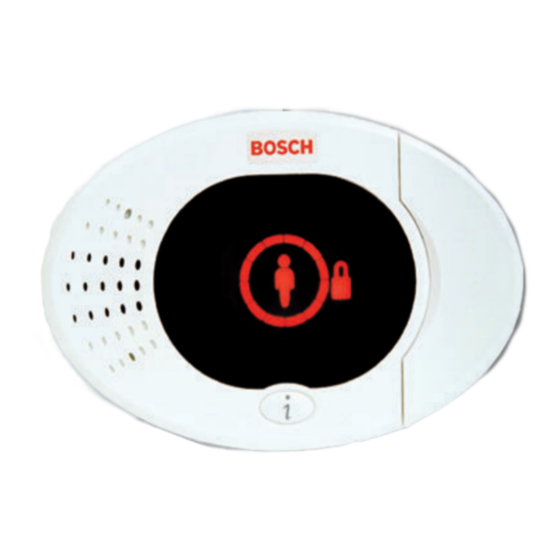
1 four-conductor, power-limited 1.2 mm (18 AWG) or 0.8 mm (22 AWG) wire At least 0.6 mm (24 AWG) twisted pair CAT5 wire. UL installations require power-limited wiring. 2014.09 | 01 | F.01U.306.221 System Reference Guide Bosch Security Systems, Inc. - Page 71 Green or amber Point walk test. Green single circle segments represent tested points. Green flashing icons Control center test. Icons alternately flash. Table 8.1: System Off Display States Bosch Security Systems, Inc. System Reference Guide 2014.09 | 01 | F.01U.306.221...
- Page 72 Red icon: Second half of Entry Delay. Broken red circle; Fire or intrusion alarm occurred. flashing red icons Flashing red circle Active alarm memory (if system is on). 2014.09 | 01 | F.01U.306.221 System Reference Guide Bosch Security Systems, Inc.
-
Page 73: Dx2010 Input Expander
As each DX2010 module is added to the system, it occupies the next available group of points. For Points 9 to 32, wireless points also occupy points in the same groups of eight as the DX2010 modules: Bosch Security Systems, Inc. System Reference Guide 2014.09 | 01 | F.01U.306.221... -
Page 74: B426 Ethernet Communication Module
B450 Conettix Plug-in Communicator Interface The Conettix Plug-in Communicator Interface creates two-way communications over commercial cellular networks for compatible control panels using a plug-in communicator (available separately). Electrical 2014.09 | 01 | F.01U.306.221 System Reference Guide Bosch Security Systems, Inc. -
Page 75: Radion Repeater
Notice! Use a supported transformer as defined in the specification table for the repeater. Do not connect power supply to a receptacle controlled by a switch. Bosch Security Systems, Inc. System Reference Guide 2014.09 | 01 | F.01U.306.221... -
Page 76: Installation Considerations
Wall and Cover Tamper Switch Transmits a tamper signal when someone removes the device from its base or pulls it away from the wall. Frequency 433.42 MHz Table 8.4: Specifications 2014.09 | 01 | F.01U.306.221 System Reference Guide Bosch Security Systems, Inc. -
Page 77: Leds
To ensure proper functionality, the device must be tested at least once every year. Accoustic Capabilities Glass types and Type Thickness thickness Plate 2.4 mm to 6.4 mm (3/32 in to 1/4 in) Bosch Security Systems, Inc. System Reference Guide 2014.09 | 01 | F.01U.306.221... -
Page 78: Installation Considerations
Avoid locations that expose the detector to possible false-alarm sources such as: – Glass airlocks and vestibule areas; – Kitchens; – Corner mounting; – Residential car garages; – Stairwells – Bathrooms; and – Small acoustically live rooms 2014.09 | 01 | F.01U.306.221 System Reference Guide Bosch Security Systems, Inc. -
Page 79: Testing
Check the battery strength of the hand-held testing device before the test. Bosch Security Systems, Inc. System Reference Guide 2014.09 | 01 | F.01U.306.221... -
Page 80: Low Battery
8.7.5 Maintenance Clean the cover with a damp (water) cloth as needed to keep it free of dust and dirt. Always test the sensor after cleaning it. 2014.09 | 01 | F.01U.306.221 System Reference Guide Bosch Security Systems, Inc. -
Page 81: Radion Tritech
Features include: – 11m x 11m (35 ft by 35 ft) coverage – Flexible mounting height – Compatible with Bosch RADION wireless systems – Draft and Insect immune – Cover activated tamper indication. Optional wall-activated tamper is included Dimension 138.00 mm x 72.00 mm x 64.00 mm... -
Page 82: Sensitivity Settings
LED to indicate the edges of the Microwave pattern. Adjust as necessary. Please reference the LED table below for LED descriptions. LED Condition Cause Steady LED PIR activation (Walk Test) Steady green Microwave activation Steady blue Alarm signal 2014.09 | 01 | F.01U.306.221 System Reference Guide Bosch Security Systems, Inc. -
Page 83: Radion Pir
An integrated wireless transmitter sends a battery report with each transmission, and transmits a supervisory signal to the control panel. Features include: – 12 m x 12 m (40 ft x 40 ft) coverage – Flexible Mounting Height Bosch Security Systems, Inc. System Reference Guide 2014.09 | 01 | F.01U.306.221... -
Page 84: Walk Testing
This 3 minute lockout time reduces unnecessary RF transmissions in high traffic areas, thereby extending battery life. Refer to the LED table below for LED descriptions. 2014.09 | 01 | F.01U.306.221 System Reference Guide Bosch Security Systems, Inc. -
Page 85: Radion Pir C
Functional range: -10°C to +49°C (+14°F to +120°F) EN 50130-5 Class II only: -10゚C to 40゚C (+14゚F to +104゚ Power/voltage One CR123A Lithium batteries, 3 VDC ( Power source type: C Low battery level: 2,15V Bosch Security Systems, Inc. System Reference Guide 2014.09 | 01 | F.01U.306.221... -
Page 86: Walk Testing
Refer to the LED table below for LED descriptions. LED condition Cause Steady blue PIR activation (Walk Test) Flashing blue Warm-up period after power-up Flashing blue (four-pulse sequence) PIR failure. Replace unit. 2014.09 | 01 | F.01U.306.221 System Reference Guide Bosch Security Systems, Inc. -
Page 87: Radion Smoke
Device testing To ensure proper functionality, the device must be tested at least once every year. Sensitivity 0.14+/- 0.04 bM/m (0.97 – 2.99%/ft obscuration – RFSM- A only) Bosch Security Systems, Inc. System Reference Guide 2014.09 | 01 | F.01U.306.221... -
Page 88: Battery Replacement
Notice! To avoid a fire department dispatch, contact central monitoring station, or put the system into Test mode before activating the detector using this method. 2014.09 | 01 | F.01U.306.221 System Reference Guide Bosch Security Systems, Inc. -
Page 89: Sensitivity Test
Flashes every 8 sec under normal operation. Detects smoke, sending an alarm. Malfunction, replace the batteries, clean the detector, or replace the optical chamber as required. Table 8.11: LED Bosch Security Systems, Inc. System Reference Guide 2014.09 | 01 | F.01U.306.221... -
Page 90: Clean The Detector And Replace The Optical Chamber
Ensure that the batteries are properly installed. Mount the detector onto the mounting base. 10. Test the detector’s sensitivity. 2014.09 | 01 | F.01U.306.221 System Reference Guide Bosch Security Systems, Inc. -
Page 91: Radion Contact Sm
– For additional security, you can use an adhesive with the screws to secure the transmitters and magnets during installation. Bosch Security Systems, Inc. System Reference Guide 2014.09 | 01 | F.01U.306.221... -
Page 92: Radion Contact Rm
0% to 93%, non-condensing Temperature (operating) Functional range: -10°C to +49°C (+14°F to +120°F) EN 50130-5 Class II only: -10゚C to 40゚C (+14゚F to +104゚F) Frequency 433.42 MHz Table 8.13: Specifications 2014.09 | 01 | F.01U.306.221 System Reference Guide Bosch Security Systems, Inc. -
Page 93: Installation Considerations
48.80 mm x 154.10 mm x 23.60 mm (1.92 in x 6.06 in x 0.93 in) Power/voltage 1.5 VDC, Lithium ( Power source type: C Low battery level: 0.9V Bosch Security Systems, Inc. System Reference Guide 2014.09 | 01 | F.01U.306.221... -
Page 94: Applications For This Product
During the installation process, use the self-adhesive Velcro strips located on the bottom of the bill trap base, to secure and stabilize the bill trap in the cash drawer. This is achieved by performing the following: 2014.09 | 01 | F.01U.306.221 System Reference Guide Bosch Security Systems, Inc. -
Page 95: Radion Universal Transmitter
Transmits a tamper signal when someone removes the device from its base or pulls it away from the wall. Frequency 433.42 MHz Table 8.15: Specifications Dual EOL Resistor Option Bosch Security Systems, Inc. System Reference Guide 2014.09 | 01 | F.01U.306.221... -
Page 96: Installation Considerations
X ᅳ Y ᅳ Z coordinates graphic. Use the table in conjunction with the graphic to determine desired distances between the magnet and the transmitter based on the type of installation (wood or metal). 2014.09 | 01 | F.01U.306.221 System Reference Guide Bosch Security Systems, Inc. -
Page 97: Reed Switch Settings
(0.87 in x 1.10 in x .59 in) Power/voltage CR123A Lithium battery, 3 VDC ( Battery replacement One Duracell DL123A, or Panasonic CR123A, or Sanyo CR123A. Check your battery yearly to ensure proper functionality. Bosch Security Systems, Inc. System Reference Guide 2014.09 | 01 | F.01U.306.221... -
Page 98: Installation Considerations
You have a variety of installation options to consider when installing the device. You must acknowledge the unique installation approach prior to installation. Some installation considerations include: – Suitable surfaces for installation include wood, steel, and aluminum. 2014.09 | 01 | F.01U.306.221 System Reference Guide Bosch Security Systems, Inc. -
Page 99: Jumper Switch Settings
Notice! Insert the jumper onto the pin prior to installing the battery. Failure to do so may result in unexpected operation of the device. Bosch Security Systems, Inc. System Reference Guide 2014.09 | 01 | F.01U.306.221... - Page 100 A single tap such as a branch in the wind lightly brushing a window can start the minor attack timer and tap count. To avoid false alarms, do not use the Minor Attack setting where stray vibrations might occur. 2014.09 | 01 | F.01U.306.221 System Reference Guide Bosch Security Systems, Inc.
- Page 101 Use the following procedure for the desired outcome. Callout ᅳ Description 1 ᅳ Jumper installed in this position enables the reed switch. 2 ᅳ Jumper installed in this position disables the reed switch. Bosch Security Systems, Inc. System Reference Guide 2014.09 | 01 | F.01U.306.221...
-
Page 102: Radion Keyfob
Pressing either the arm or disarm button causes the LED to flash for about 2 sec., indicating the keyfob sent commands to the control panel. Notice! Pressing the Arm and Disarm buttons in unison for 1 sec transmits a panic alarm. 2014.09 | 01 | F.01U.306.221 System Reference Guide Bosch Security Systems, Inc. -
Page 103: Radion Keyfob Fb
To operate these buttons, simply press and hold either button for at least one sec in order for the desired feature to work. – Uniquely coded arm and disarm buttons – Panic alarm – LED indicator Bosch Security Systems, Inc. System Reference Guide 2014.09 | 01 | F.01U.306.221... -
Page 104: Radion Panic
The RADION panic offers the following features: – Each transmitter has a unique code – Panic alarm signal – One or two button versions – LED indicator – Optional accessories 2014.09 | 01 | F.01U.306.221 System Reference Guide Bosch Security Systems, Inc. - Page 105 Table 8.18: Specifications Notice! Please note, the battery does not come installed. Verify that the correct battery as defined in the specification table is installed in the proper polarity. Bosch Security Systems, Inc. System Reference Guide 2014.09 | 01 | F.01U.306.221...
- Page 106 Wrist Strap Wrist Strap transmitters provide single or two-button activation confirmed by emitting LED flashes with all transmissions to clearly show users when the unit is operating. 2014.09 | 01 | F.01U.306.221 System Reference Guide Bosch Security Systems, Inc.
-
Page 107: Programming Details And Defaults
(control centers that are not currently engaged in a command). Set Demo Mode to 2 (Demo Mode Auto On/Off). Enter the telephone menu. Bosch Security Systems, Inc. System Reference Guide 2014.09 | 01 | F.01U.306.221... - Page 108 224. RPS Automatic Call In Time (Hours) 202. PSTN or GSM Connection Select the type of telephone connection the system will use to send reports to the central station. 203. Voice Format Repeat Count 2014.09 | 01 | F.01U.306.221 System Reference Guide Bosch Security Systems, Inc.
- Page 109 Intrusion and Fire Latching: Output turns on when an intrusion or fire alarm occurs. To turn off output, turn off system if it is already on, or acknowledge alarm if system is off. Fire alarms take priority over intrusion alarms. Bosch Security Systems, Inc. System Reference Guide 2014.09 | 01 | F.01U.306.221...
- Page 110 – Momentary Keyswitch: Turn the system on or off using a momentary keyswitch. – Maintained Keyswitch: Turn the system on or off using a maintained keyswitch. 2014.09 | 01 | F.01U.306.221 System Reference Guide Bosch Security Systems, Inc.
-
Page 111: Country Codes
Canada New Zealand China Norway Croatia Poland Czech Republic Portugal Denmark Romania Egypt Russian Federation Finland Spain France Sweden Germany Taiwan Greece Thailand Hong Kong Turkey Hungary Ukraine Bosch Security Systems, Inc. System Reference Guide 2014.09 | 01 | F.01U.306.221... -
Page 112: Country Code Specific Default Programming Codes
Country Code Specific Default Programming Codes Prog Country Codes Item 110 112 000 112 112 112 110 000 112 999 9011 9021 9031 9041 9051 9061 9071 9081 9012 9022 2014.09 | 01 | F.01U.306.221 System Reference Guide Bosch Security Systems, Inc. - Page 113 9052 9062 9072 9082 9092 9102 9112 9122 9132 9142 9152 9162 9172 9182 9192 9202 9212 9222 9223 9242 9252 9262 9272 9282 9292 9302 9612 9322 Bosch Security Systems, Inc. System Reference Guide 2014.09 | 01 | F.01U.306.221...
- Page 114 | Programming Details and Defaults Easy Series Control Panel Prog Country Codes Item 9015 9025 9035 9045 9055 9065 9075 9085 2014.09 | 01 | F.01U.306.221 System Reference Guide Bosch Security Systems, Inc.
- Page 115 Programming Details and Defaults | en Prog Country Codes Item 112 000 112 110 9011 9021 9031 9041 9051 9061 9071 9081 9012 9022 9032 9042 9052 9062 9072 9082 Bosch Security Systems, Inc. System Reference Guide 2014.09 | 01 | F.01U.306.221...
- Page 116 Country Codes Item 9092 9102 9112 9122 9132 9142 9152 9162 9172 9182 9192 9202 9212 9222 9223 9232 9242 9252 9262 9272 9282 9292 9302 9312 9322 2014.09 | 01 | F.01U.306.221 System Reference Guide Bosch Security Systems, Inc.
- Page 117 Easy Series Control Panel Programming Details and Defaults | en Prog Country Codes Item 9015 9025 9035 9045 9055 9065 9075 9085 Bosch Security Systems, Inc. System Reference Guide 2014.09 | 01 | F.01U.306.221...
- Page 118 Bosch Security Systems, Inc. Bosch Sicherheitssysteme GmbH 130 Perinton Parkway Robert-Bosch-Ring 5 Fairport, NY 14450 85630 Grasbrunn Germany www.boschsecurity.com © Bosch Security Systems, Inc., 2014...