Honeywell Sensepoint XCD Technical Manual
Gas detector
Hide thumbs
Also See for Sensepoint XCD:
- Calibration manual (6 pages) ,
- Installation manual (6 pages) ,
- Technical manual (85 pages)
Table of Contents
Advertisement
Advertisement
Table of Contents

Related Manuals for Honeywell Sensepoint XCD


Summary of Contents for Honeywell Sensepoint XCD
- Page 1 Technical Manual Sensepoint XCD Gas Detector...
-
Page 2: Safety
Operating Manual. Cautions appear in the sections/sub-sections of the document where they apply. WARNINGS Sensepoint XCD is designed for installation and use in Zone 1 or 2 hazardous areas in many countries including Europe and for Class 1 Division 1 or 2 area applications in North America. -
Page 3: Information
The Start-up/Surge/In rush current is dependant on the type of power supply used. The typical start-up current for Sensepoint XCD is less than 800mA. Measure the start-up current using the specific power supply before installation to ensure suitability for your application. -
Page 4: Table Of Contents
Sensepoint XCD Technical Manual SPXCDHMANEN Issue 2 3 Table of contents 1 Safety 2 Information 3 Table of contents 4 Introduction 4.1 Transmitter 4.2 Flammable, Toxic Oxygen Gas sensors 4.3 Accessories 5 Installation 5.1 Mounting and location 5.2 Mounting the transmitter 5.3 Installing the sensor... - Page 5 Sensepoint XCD Technical Manual SPXCDHMANEN Issue 2 14 General specification 15 Ordering information 16 Warranty statement 17 Installation Drawing 17.1 Mechanical Installation Drawing 17.2 Electronic Connection Drawing 17.3 Duct Mounting Drawing 17.4 Collecting Cone Drawing 17.5 Mounting Bolt Assy Drawing 17.6 Mounting Bracket Drawing...
-
Page 6: Introduction
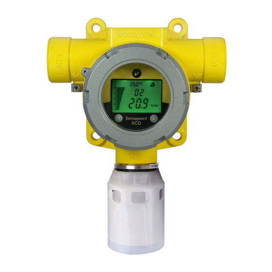
The Sensepoint XCD (“Exceed”) comprises a gas detector transmitter and a choice of sensors for detecting flammable gas, toxic gas and oxygen. The construction of Sensepoint XCD allows it to be used in hazardous area locations; it may also be used in other areas not classified as hazardous. -
Page 7: Transmitter
Diagram 2: Sensepoint XCD Display and Magnetic Switches 4.2 Flammable, Toxic Oxygen Gas sensors The Sensepoint XCD transmitter is designed to work with a variety of gas sensors for detecting flammable gases. Sensepoint XCD sensors use NDIR infrared and electro- catalytic technologies. -
Page 8: Accessories
Diagram 3: Sensepoint XCD Flammable, Toxic and Oxygen Sensor Cartridge 4.3 Accessories A range of accessories are available to allow use of Sensepoint XCD in a wide variety of applications. These including mounting brackets, maintenance tools, weather housings, flow housing, collecting cone, duct mounting kit and sensor junction boxes. - Page 9 Sensepoint XCD Technical Manual SPXCDHMANEN Issue 2 Collecting cone Duct mounting kit The Duct Mounting Kit (P/N: SPXCDDMK) The Collecting Cone (P/N: SPXCDCC) is an is an optional accessory that is designed for optional accessory that may be fitted to the applications to allow the monitoring for the Weather Protection.
-
Page 10: Installation
SPXCDHMANEN Issue 2 5 Installation WARNINGS Sensepoint XCD is designed for installation and use in Zone 1 or 2 hazardous areas in many countries including Europe and for Class 1 Division 1 or 2 area applications in North America. Installation must be in accordance with the recognized standards of the appropriate authority in the country concerned. -
Page 11: Mounting And Location
5.2 Mounting the transmitter The Sensepoint XCD transmitter has an integral mounting plate consisting of four mounting holes on the transmitter body. The transmitter may be fixed directly to a surface mounting, or to a horizontal or vertical pipe/structure, 40.0-80.0mm (1.6 to 3.1 inches) in... - Page 12 SPXCDHMANEN Issue 2 Diagram 5: Mounting arrangements To mount the Sensepoint XCD transmitter to a Vertical or Horizontal pipe/structure, use the optional XCD Mounting Kit and following procedure: 1. Fit the four spring washers, then the plain washers to the M8 x 80mm SS316 bolts.
-
Page 13: Installing The Sensor
Diagram 6: Installing the Sensor WARNINGS Care should be taken when removing and refitting the Sensepoint XCD plug-in Sensor to the Sensor Socket so that damage to the connection pins can be avoided. If using an anti-seize compound, the threads should be thinly coated with an approved silicone free compound e.g. -
Page 14: Electrical Connections
Electrical connections WARNINGS Sensepoint XCD is designed for installation and use in Zone 1 or 2 hazardous areas in many countries including Europe and Class 1 Division 1 or 2 area applications in North America. Installation must be in accordance with the recognized standards of the appropriate authority in the country concerned. -
Page 15: Transmitter Wiring
Caution: All electrical connections should be made in accordance with any relevant local or national legislation, standards or codes of practice. The Sensepoint XCD transmitter may be wired in either Current SOURCE or Current SINK configuration. These two options are offered to allow greater flexibility in the type of control system that it can be used with. -
Page 16: Terminal Connections
Sensepoint XCD Technical Manual SPXCDHMANEN Issue 2 6.2 Terminal connections Note: Ensure that none of the wires in the terminal area cause an obstruction when refitting the Display Module. Ensure that the socket on the Display Module is fully engaged in the Display Module Connector on the Terminal Module. -
Page 17: Power
SPXCDHMANEN Issue 2 6.3 Power The Sensepoint XCD transmitter requires a power supply from the controller of between 16Vdc and 32Vdc. Ensure that a minimum supply of 16Vdc is measured at the sensor, taking into account the voltage drop due to cable resistance. -
Page 18: Cabling
Sensepoint XCD Technical Manual SPXCDHMANEN Issue 2 6.4 Cabling The use of industrial grade, suitably armoured field cable is recommended. For example, screened 3 cores (plus screen 90% coverage), suitably mechanically protected copper cable with a suitable M20 explosion-proof gland, or ¾” NPT steel conduit, with 0.5 to 2.5 mm2 (20 to 13 AWG) conductors. -
Page 19: Ground Terminal Wiring
Sensepoint XCD Technical Manual SPXCDHMANEN Issue 2 The Earth Screen of the field cable should be “tied to Earth” or connected to Ground at one point only. It is common practise to adopt a STAR EARTH connection regime where all instrumentation Screens are connected at one common point. -
Page 20: Default Configuration
Rising Flammable IR 100%LEL 20%LEL Rising 40%LEL Rising Flammable CAT 100%LEL 20%LEL Rising 40%LEL Rising Carbon Dioxide IR 2.00%Vol 0.40%Vol Rising 0.80%Vol Rising For details of how to change the configuration of the Sensepoint XCD please refer to section 13. -
Page 21: Normal Operation
SPXCDHMANEN Issue 2 8 Normal Operation Sensepoint XCD is supplied configured and ready for use according to the “Default Settings” table shown above. However these setting may be tailored to a specific application requirement using the Sensepoint XCD configuration menu system. -
Page 22: System Status
Sensepoint XCD Technical Manual SPXCDHMANEN Issue 2 8.2 System Status Display indications, current output and relay states for various operational conditions are shown in the following table. For further details of error messages and trouble shooting see section 12.3. System Status... -
Page 23: Magnetic Wand Activation
Communication with the XCD is achieved by positioning the Magnetic Wand at one of three different positions on the front glass window of the Sensepoint XCD transmitter. Activation of the switches is verified by observing the Magnetic Wand Activation Icon on the LCD display... -
Page 24: First Time Switch On (Commissioning)
Sensepoint XCD Technical Manual SPXCDHMANEN Issue 2 9 First time switch on (Commissioning) WARNING The following procedure requires the Transmitter Cover to be removed while carrying out supply voltage checks. Therefore the appropriate permits to work should be sought in preparation. - Page 25 Sensepoint XCD Technical Manual SPXCDHMANEN Issue 2 Note: For a full description of each screen shown in Diagram 15., please refer to Section 13.3 “Review Mode” of this Manual. Diagram 15: Normal Start up procedure (For the CO sensor version) 11.The warm up countdown of 60 seconds (depending on the gas type) is then...
-
Page 26: Response Check And Calibration
SPXCDHMANEN Issue 2 10 Response Check and Calibration It is recommended to periodically carry out a gas response check on the Sensepoint XCD to ensure correct operation. This may be done in two ways; 1. A simple Response Check often referred to as a “BUMP TEST” is a test using calibration gas applied to the sensor via the nozzle of the Weather Protection or using the Sensepoint XCD Gassing Cap. - Page 27 Sensepoint XCD Technical Manual SPXCDHMANEN Issue 2 (ZERO CALIBRATION) 1. If the ambient air is NOT considered reliable to use to set the ZERO, then remove the weather protection and fit the Gassing Cap accessory (see Section 4.3) onto the sensor and apply a clean source of zero gas or compressed air.
- Page 28 12. The display will show the current gas reading, and the ‘ ’ icon flashes. 13. Connect the regulator to the span gas cylinder. 14. Apply the span gas to the sensor using the Sensepoint XCD Gassing Cap (see section 4.7 for description). The live gas reading is displayed. When the reading is ’...
-
Page 29: Zeroing And Span Calibration Of Hydrogen Sulfide Sensors
Sensepoint XCD Technical Manual SPXCDHMANEN Issue 2 19. Promptly switch off the calibration span gas and remove the Sensepoint XCD Gassing Cap from the sensor to allow the gas to disperse. 20. When the reading falls below 50% of the calibration gas level the display indicates a countdown (up to 180 seconds dependant on gas type). -
Page 30: General Maintenance
Access to the interior of the transmitter, when carrying out any work, must only be conducted by trained personnel. Care should be taken when removing and refitting the Sensepoint XCD plug-in Sensor Cartridge to the Sensor Socket so that damage to the connection pins can be avoided. -
Page 31: Servicing
Do not expose sensor to organic solvents or flammable liquids. Care should be taken when removing and refitting the Sensepoint XCD plug-in Sensor Cartridge to the Sensor Socket so that damage to the connection pins can be avoided. - Page 32 Sensor Retainer Locking Grub Screw Diagram 13: Sensor Replacement To replace the plug-in sensor of a Sensepoint XCD Sensor Socket use the following procedure: 1. Important: Remove the Power from the Sensepoint XCD Transmitter 2. Remove the Weather Protection or other accessories from the sensor socket thread.
-
Page 33: Replacing Modules Within The Transmitter
Sensepoint XCD Technical Manual SPXCDHMANEN Issue 2 12.2 Replacing Modules within the Transmitter Two replaceable module assemblies are located within the transmitter housing. The Display Module and the Terminal Module. The Display Module is simply removed by unplugging it from the Terminal Module (this procedure is done during normal installation). -
Page 34: Faults And Warnings
Sensepoint XCD Technical Manual SPXCDHMANEN Issue 2 12.3 Faults and Warnings The table below provides details of possible error. Message Description Action The unit has not been calibrated for the configured calibration interval W-01 Calibration needed Calibration is necessary due to change... -
Page 35: Menu's And Advanced Configuration
Sensepoint XCD Technical Manual SPXCDHMANEN Issue 2 13 Menu’s and Advanced Configuration 13.1 Abort Function In Review Mode or Configuration Mode the user can escape one step back from the current position using the Abort Function. To do this the user must activate the Enter switch for more than 3 seconds with the Magnetic Wand. - Page 36 Sensepoint XCD Technical Manual SPXCDHMANEN Issue 2 Menu Display Description Execute zero/span calibration Set calibration gas level Set Calibration After zero, the option exists to proceed with span calibration, or return to the Menu. Select the type of sensor from the sensor list.
- Page 37 Sensepoint XCD Technical Manual SPXCDHMANEN Issue 2 Configure relay on delay time, relay off delay Relay Operation time and latch/non-latch Set location (or TAG number) Set Location Change temperature display unit. Set Temperature Unit °C (Celcius) or °F (Fahrenheit) Simulate alarm situation to check the alarm...
-
Page 38: Configuration Mode Operation Table
Sensepoint XCD Technical Manual SPXCDHMANEN Issue 2... - Page 39 Sensepoint XCD Technical Manual SPXCDHMANEN Issue 2...
-
Page 40: Sensor / Gas Selection
Sensepoint XCD Technical Manual SPXCDHMANEN Issue 2 13.3 Sensor / Gas Selection NOTE: This Configuration option is not available for XCD units with EC sensors 13.3.1 Sensor Selection “Select Sensor” sets the identity of the type of mV sensor attached to the XCD when XCD does not detect the sensor type automatically. - Page 41 Sensepoint XCD Technical Manual SPXCDHMANEN Issue 2 Sensor type Gas type Gas Name displayed Ir-1 Ir-3 Cb-1 Str1 to Str8 Gas selection is dependent on the type of sensor attached to the XCD. If Ir-1/Ir-3 sensor is attached, then a user can only select CO /mEt gas respectively.
-
Page 42: Review Mode
Sensepoint XCD Technical Manual SPXCDHMANEN Issue 2 13.4 Review Mode The instrument will enter Review mode when the “Enter” switch is activated with the Magnetic Wand and held for around one second. Names, displays and descriptions for each review item in Review Mode are shown in the following table. - Page 43 Sensepoint XCD Technical Manual SPXCDHMANEN Issue 2 Location Location in which the transmitter is installed Power Power voltage* Temperature Internal Transmitter temperature* Peak conc. Maximum concentration detected up to now Test Result There is no fault detected. Table 8: Transmitter menu descriptions...
- Page 44 Sensepoint XCD Technical Manual SPXCDHMANEN Issue 2 Menu Switch (1s to 3s) Review Monitoring Mode Mode Abort Auto end to cycle S/W Version Test Result 2 second delay 2 second delay SRS Version Peak Reading 2 second delay 2 second delay...
-
Page 45: General Specification
+/- 30% of applied gas from -20°C to -40°C (-4°F to -40°F) and +55°C to +65°C (+131°F to +149°F). Long term operation at this range may cause decline in sensor performance. Contact Honeywell Analytics for any additional data or details. Certification GB Ex d IIC T4 GB3836.1&2 -2000, PA, (CCCF –... -
Page 46: Ordering Information
SPXCDHMANEN Issue 2 15 Ordering information Part Number Description Sensepoint XCD transmitter and sensor KIT (ATEX/IECEx/AP*, ADC12 and M20 Entry) SPXCDAAMFX ATEX/IECEx/AP* approved Methane CAT 0-100%LEL (20 to 100%LEL, 10%LEL) with ADC12, M20 Entry SPXCDAAMRX ATEX/IECEx/AP* approved Methane IR 0-100%LEL (20 to 100%LEL, 10%LEL) with ADC12, M20 Entry SPXCDAAMO1 ATEX/IECEx/AP* approved Oxygen 25.0%/Vol with ADC12, M20 Entry... - Page 47 Sensepoint XCD Technical Manual SPXCDHMANEN Issue 2 SPXCDUSNO1 UL approved Oxygen 25.0%/Vol with 316SS, 3/4"NPT Entry SPXCDUSNHX UL approved Hydrogen Sulfide 0-50ppm (10.0 to 100.0ppm, 1ppm) with 316SS, 3/4"NPT Entry SPXCDUSNCX UL approved Carbon Monoxide 0-300ppm (100 to 1000ppm, 100ppm) with 316SS, 3/4"NPT Entry SPXCDUSNG1 UL approved Hydrogen 0-1000ppm with 316SS, 3/4"NPT Entry...
-
Page 48: Warranty Statement
Analytics reserves the right to charge for any site attendance where any fault is not found with he the equipment. Honeywell Analytics shall not be liable for any loss or damage whatsoever or howsoever occasioned which may be a direct or indirect result of the use or operation of the Contract Goods by the Buyer or any Party. -
Page 49: Installation Drawing
Sensepoint XCD Technical Manual SPXCDHMANEN Issue 2 17 Installation Drawing 17.1 Mechanical Installation Drawing... -
Page 50: Electronic Connection Drawing
Sensepoint XCD Technical Manual SPXCDHMANEN Issue 2 17.2 Electronic Connection Drawing... -
Page 51: Duct Mounting Drawing
Sensepoint XCD Technical Manual SPXCDHMANEN Issue 2 17.3 Duct Mounting Drawing... -
Page 52: Collecting Cone Drawing
Sensepoint XCD Technical Manual SPXCDHMANEN Issue 2 17.4 Collecting Cone Drawing... -
Page 53: Mounting Bolt Assy Drawing
Sensepoint XCD Technical Manual SPXCDHMANEN Issue 2 17.5 Mounting Bolt Assy Drawing... -
Page 54: Mounting Bracket Drawing
Sensepoint XCD Technical Manual SPXCDHMANEN Issue 2 17.6 Mounting Bracket Drawing... -
Page 55: Certification
Sensepoint XCD Technical Manual SPXCDHMANEN Issue 2 18 Certification 18.1 China GB Ex and PA China GB Ex (Chinese Version):... - Page 56 Sensepoint XCD Technical Manual SPXCDHMANEN Issue 2 China GB Ex (English Version):...
- Page 57 Sensepoint XCD Technical Manual SPXCDHMANEN Issue 2 China PA Certification:...
-
Page 58: Korea Ktl
Sensepoint XCD Technical Manual SPXCDHMANEN Issue 2 18.2 Korea KTL... -
Page 59: European Atex
Sensepoint XCD Technical Manual SPXCDHMANEN Issue 2 18.3 European ATEX ATEX For Transmitter:... - Page 60 Sensepoint XCD Technical Manual SPXCDHMANEN Issue 2 ATEX for Sensor...
-
Page 61: International Iec
Sensepoint XCD Technical Manual SPXCDHMANEN Issue 2 18.4 International IEC IEC Ex for Transmitter... - Page 62 Sensepoint XCD Technical Manual SPXCDHMANEN Issue 2 IEC Ex for Sensor...
-
Page 63: Atex Name Plate
Sensepoint XCD Technical Manual SPXCDHMANEN Issue 2 18.5 Sensepoint XCD ATEX Name Plate... -
Page 64: Ul Name Plate
Sensepoint XCD Technical Manual SPXCDHMANEN Issue 2 18.6 Sensepoint XCD UL Name Plate... -
Page 65: Sensor Cartridges Label
Sensepoint XCD Technical Manual SPXCDHMANEN Issue 2 18.7 Sensor Cartridges Label... -
Page 66: Cross Interference And Cross Calibration
19 Cross Interference and Cross Calibration 19.1 Cross Interference Table for Toxic and Oxygen This below table shows the relative cross sensitivity of the Sensepoint XCD to other gases. “Gas Type” indicated the XCD sensor type fitted to the XCD. “Gas Type Applied”... -
Page 67: Cross Calibration Flammable Gas Detector
Therefore, it is possible to carry out a “cross calibration” using another hydrocarbon gas/air mixture. When the Sensepoint XCD Combustible LEL sensor is to be calibrated with a gas which is different to the gas or vapour to be detected, the following cross calibration procedure may... - Page 68 Sensepoint XCD Technical Manual SPXCDHMANEN Issue 2 Styrene Tetra hydrafuran Toluene Triethylamine Xylene Table 11 . Star Rating of Gases To cross calibrate the SG16B flammable gas detector catalytic bead: (1) Obtain the star rating for both the calibration test gas and the gas to be detected from...
- Page 69 62% LEL to give an accurate measuring scale for 0-100%LEL Ethylene, when using 50% LEL Methane as the calibration gas. Please contact your local Honeywell Analytics sales or service distributor, or regional office should further clarification or additional information be required.
- Page 70 Tel: +1 847 955 8200 Toll free: +1 800 538 0363 Fax: +1 847 955 8208 detectgas@honeywell.com Asia Pacific Honeywell Analytics Asia Pacific Please Note: #508, Kolon Science Valley (I) While every effort has been made to ensure accuracy in this publication, no responsibility 187-10 Guro-Dong, Guro-Gu can be accepted for errors or omissions.