Table of Contents
Advertisement
Advertisement
Table of Contents

Related Manuals for Honeywell Searchline Excel


Summary of Contents for Honeywell Searchline Excel
- Page 1 Technical Handbook Searchline Excel Infrared Gas Detectors...
-
Page 2: Safety
Please pay particular attention to the Safety Warnings. WARNINGS 1. The Searchline Excel gas detector is certified for and intended for use in potentially hazardous areas. Install and use the Searchline Excel gas detector in accordance with the latest regulations. For installations in the UK, the Code of Practice SELECTION, INSTALLATION AND MAINTENANCE OF ELECTRICAL APPARATUS FOR USE IN POTENTIALLY EXPLOSIVE ATMOSPHERES should be strictly observed. - Page 3 Honeywell Analytics Limited reserve the right to change or revise the information supplied in this document without notice and without obligation to notify any person or organisation of such revision or change. If further details are required that do not appear in this manual, contact Honeywell Analytics Limited or one of their agents.
-
Page 4: Table Of Contents
MAN0530 Issue 10 - 11/09 Searchline Excel 2104M0506 CONTENTS SAFETY 1. INTRODUCTION 2. OVERVIEW Introduction Transmitter Receiver Adjustable Mountings 3. INSTALLATION AND OPERATION 3.1 Introduction 3.2 Siting and Mounting 3.3 Electrical connections 3.4 Power supply 3.5 Unpacking 3.6 Installation procedure 3.7 Alignment and commissioning... - Page 5 MAN0530 Issue 10 - 11/09 Searchline Excel 2104M0506 CONTENTS APPENDIX A - HANDHELD INTERROGATOR A.1 Introduction A.2 Overview A.3 Connection to System A.4 Basic User Tasks A.5 Menus A.6 Problem Solving A.7 specification APPENDIX B - GLOSSARY B.1 Terminology B.2 Measurement Units B.3 Abbreviations...
-
Page 6: Introduction
MAN0530 Issue 10 - 11/09 Searchline Excel 2104M0506 1. INTRODUCTION Searchline Excel is a hydrocarbon gas detection system that is available in two versions: • Searchline Excel Open-Path Gas Detector • Searchline Excel Cross-Duct Gas Detector For information regarding the Cross-Duct Excel contact Honeywell Analytics. Searchline Excel Open-Path Gas Detector (OPGD) consists of a Transmitter unit that sends an infrared beam to a Receiver unit up to 200 metres away, and can be located where a flammable hydrocarbon gas cloud is likely to occur. - Page 7 Note: Provides useful/helpful/additional information. If more information beyond the scope of this technical handbook is required please contact Honeywell Analytics. Associated Documents Searchline Excel Open-Path Infrared Gas Detector Basic Installation Guide Part No: 2104M0510 Searchline Excel Cross-Duct Infrared Gas Detector...
-
Page 8: Overview
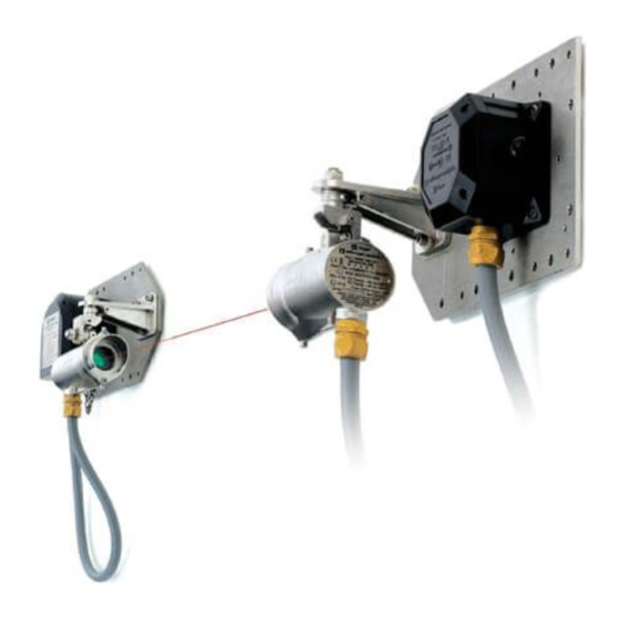
MAN0530 Issue 10 - 11/09 Searchline Excel 2104M0506 2. OVERVIEW INTRODUCTION Each type of Searchline Excel gas detector consists of two units, a Transmitter and a Receiver. This separate Transmitter/Receiver configuration provides the most reliable basis for open path gas detection. DVC100(M) MK2 or DX100(M) (or other junction box) Mounting plate... -
Page 9: Transmitter
Long Range 120 – 200m (390ft – 650ft) When designing an installation for Searchline Excel it is important that the correct range of the gas detector for each path to be monitored is selected and specified. The Transmitter and Receiver are each mounted upon robust, adjustable mounting brackets. These brackets bolt to a mounting plate, which is designed to accommodate a variety of junction boxes, accessories and mechanical mounting configurations. The small size and flexibility of... -
Page 10: Receiver
(GND). RECEIVER The Searchline Excel Receiver collects infrared radiation from the Transmitter and performs measurements to enable hydrocarbon gases in the beam path to be detected. Infrared radiation is collected by a single, silicon lens, which is common to both the sample and reference measurement channels. - Page 11 2. OVERVIEW 417mm (SR) 160mm The solid state, photovoltaic detectors used in Searchline Excel provide an exceptional dynamic range and superb temperature and long term stability. These features contribute strongly to the solar immunity and stability of Searchline Excel. The Receiver contains all of the electronics necessary to amplify, condition and process the signals received by the infrared detectors.
-
Page 12: Adjustable Mountings
MAN0530 Issue 10 - 11/09 Searchline Excel 2104M0506 2. OVERVIEW ADjUSTABLE MOUNTINGS The adjustable mountings are: • Purpose-built for Transmitter and Receiver. • Robust. • Rigid and stable. • Made from stainless steel. • Fully adjustable for alignment Coarse and fine settings in both horizontal and vertical planes. Adjustment range: Vertical ±45 Horizontal ±90... -
Page 13: Installation And Operation
For each installation, an installation check sheet should be completed and returned to Honeywell Analytics or their agents. Details of this check sheet are given at the end of this chapter. Note:... -
Page 14: Siting And Mounting
3.2 SITING AND MOUNTING 3.2.1 General When designing an installation for a Searchline Excel gas detector it is important to give consideration to where it is to be located, what potential sources of problems may be encountered in this location and how the unit is to be mounted and supported. - Page 15 Note: The heated optics have not been evaluated as part of the performance testing relating to the FM approval and therefore are not considered part of the performance approval. deluge and flooding - Searchline Excel is rated IP66/67 and as such will not be damaged by occasional deluge or flooding. However, during such instances the unit will completely lose its IR signal and will enter the BEAM-BLOCK/FAULT state. Also, when the deluge/flooding...
- Page 16 MAN0530 Issue 10 - 11/09 Searchline Excel 2104M0506 3. INSTALLATION AND OPERATION Excel Gas Detector type Path length between units Short Range 5 - 40m (15 - 130ft) Medium Range 20 - 120m (65 - 390ft) Long Range 120 - 200m...
- Page 17 Note: The pipe can be filled with concrete to provide extra robustness if necessary. 3.2.5 Orientation Searchline Excel is solar immune and therefore there is no need to take account of the sun’s movement when considering orientation. When positioning the units do not install them with the optical axis at an angle greater than 45...
-
Page 18: Electrical Connections
Preferably, the case (internally connected to the green/yellow GND wire) should be connected to a low noise instrument (clean) earth. See also para e. below. In order to facilitate electrical isolation of the Searchline Excel from a noisy earth an isolation kit is supplied. This kit should be fitted as standard unless local regulations forbid this. - Page 19 MAN0530 Issue 10 - 11/09 Searchline Excel 2104M0506 3. INSTALLATION AND OPERATION All electrical equipment connected to the gas detector should comply with EN61000-6- 3:2007 and EN61000-6-2:2005. The 24V supply should be free from large transients and fluctuations. The field cabling conductors should have sufficient cross sectional area to ensure that the minimum supply voltage applied to the gas detector is 18V at a current of 420mA.
- Page 20 3.3.4 Transmitter Connections CONTROL EXCEL CONTROL EXCEL CABINET TRANSMITTER CABINET TRANSMITTER Honeywell Analytics Junction Box CONNECTIONS WIRING CONNECTIONS JUNCTION BOX WIRING 00780-A-0100 CABLE SCREEN CABLE SCREEN GREEN/YELLOW (EARTH) GREEN/YELLOW (EARTH)
- Page 21 MAN0530 Issue 10 - 11/09 Searchline Excel 2104M0506 3. INSTALLATION AND OPERATION 3.3.5 Remote Installations For remote or difficult-to-access installations, the DVC100(M) MK2 or DX100(M) can be positioned in a convenient location by using an intervening junction box (e.g. Hawke/Bartec) attached to the receiver's mounting plate.
- Page 22 MAN0530 Issue 10 - 11/09 Searchline Excel 2104M0506 3. INSTALLATION AND OPERATION Wiring with dX100(m) See also DX100 Termination Unit's technical Handbook. LOCAL JUNCTION BOX (mounted on Receiver mounting plate) CABLE SCREEN EXCEL GREEN/YELLOW (EARTH) EXCEL RECEIVER Same potential as Excel body and conduit...
-
Page 23: Power Supply
3.4 POWER SUPPLY 3.4.1 General The Searchline Excel gas detector is designed to be operated from a nominal 24V DC supply. The supply voltage at the terminals must be within the range 18 to 32V. The unit maximum power consumption and cable lengths are as follows:... -
Page 24: Unpacking
(2) Check the contents for damage and against the packing note for deficiencies. In the event of damage or loss in transit, notify the carrier and Honeywell Analytics or your local agent immediately. The gas detector consists of the following items: Where alternative component sizes are given the size depends on the version of unit, i.e.mid/long range version or short range version. - Page 25 MAN0530 Issue 10 - 11/09 Searchline Excel 2104M0506 3. INSTALLATION AND OPERATION 2 x Mounting Plates 2 x Mounting Brackets (with grub screws) 2 x Pivot Blocks 4 x Adjustment Clamps (with grub screws) (with grub screws) 4 x Nuts...
- Page 26 MAN0530 Issue 10 - 11/09 Searchline Excel 2104M0506 3. INSTALLATION AND OPERATION Basic Installation Guide 2 x Allen (Hex) Keys (3mm) Ensure that the installer/end user of the equipment receives the technical documentation (operating instructions, manuals, etc.) contained in the packaging.
-
Page 27: Installation Procedure
3. INSTALLATION AND OPERATION 3.6 INSTALLATION PROCEDURE 3.6.1 General Searchline Excel is designed to allow installation and alignment to be performed by a single technician. The installation procedure is split into mechanical installation and electrical installation. Each unit needs to be mounted to a supporting structure before making the electrical connections. - Page 28 6mm thick 133.2 stainless steel plate 299.2 Notes: Drawing is not to scale. Mounting plate fixing holes are clear. Searchline Excel gas detector component mounting holes are tapped. The mounting plate fixings are not supplied. Identity Quantity Size Used For 7.5mm...
- Page 29 MAN0530 Issue 10 - 11/09 Searchline Excel 2104M0506 3. INSTALLATION AND OPERATION M6 tapped DVC100(M) junction box mounting. M6 tapped DVC100 (M) MK2 junction box (used in conjunction with bottom two D holes) M10 tapped DX100(M) junction box mounting. M6 tapped Killark/Akron junction box mounting.
- Page 30 MAN0530 Issue 10 - 11/09 Searchline Excel 2104M0506 3. INSTALLATION AND OPERATION 2.5in. U-bolt - 4-off (not supplied) using A holes Mounting Plate Fixed to Twin Pipes/Poles Fit an adjustment clamp to the unit’s pivot block mounting stud so that it sits on the stud’s shoulder.
- Page 31 MAN0530 Issue 10 - 11/09 Searchline Excel 2104M0506 3. INSTALLATION AND OPERATION Ensure that the adjustment clamp's stub lever is approximately centrally positioned between the mounting bracket’s grubscrews. Adjust the screws if required. Fit an adjustment clamp to the unit’s mounting stud so that it sits on the stud’s shoulder.
- Page 32 MAN0530 Issue 10 - 11/09 Searchline Excel 2104M0506 3. INSTALLATION AND OPERATION Receiver Transmitter Note: For information about alternative types of junction box see section 3.6.2 Electrical Installation. (11) Measure and record the distance (in metres) between the Transmitter and Receiver units.
-
Page 33: Alignment And Commissioning
Do not attempt to view the Sun through the optical telescope. 3.7.1 General In order to avoid unnecessary problems, alignment and commissioning of Searchline Excel gas detectors should only be performed by personnel trained by Honeywell Analytics. To ensure optimum performance the gas detector Transmitter and Receiver units must be accurately aligned with a clear line of sight between them. - Page 34 MAN0530 Issue 10 - 11/09 Searchline Excel 2104M0506 3. INSTALLATION AND OPERATION Fine adjustment is then achieved by means of mounting bracket and pivot block grubscrews which move levers on the adjustment clamps, fitted to the pivot block and unit studs, and hence the unit. After initial mechanical setup the units are powered up and the mechanical alignment can be optimised and verified electronically by means of the associated Handheld Interrogator linked to the Receiver.
- Page 35 MAN0530 Issue 10 - 11/09 Searchline Excel 2104M0506 3. INSTALLATION AND OPERATION 3.7.2 Alignment Procedure The following summarises the alignment procedure: • Basic gas detector alignment, see section 3.7.3. • Accurate alignment of Transmitter and Receiver using the appropriate alignment telescope, see section 3.7.4. • Power-up and verify alignment using SHC1 Handheld Interrogator linked to the Receiver, see section 3.7.5.
- Page 36 MAN0530 Issue 10 - 11/09 Searchline Excel 2104M0506 3. INSTALLATION AND OPERATION Excel unit Excel unit Alignment telescope assembly mounting pad (3 off) Trident-type Non-Trident-type After deciding from the table which alignment telescope to use for the Excel units being aligned the telescope assembly must be fitted to each of the units in turn starting with the Transmitter.
- Page 37 MAN0530 Issue 10 - 11/09 Searchline Excel 2104M0506 3. INSTALLATION AND OPERATION Telescope viewfinder Alignment telescope Datum Cowl mount Mirror Excel unit assembly Mounting latch assembly Latch (2 off) Locate the latch mounting hooks behind the back of the unit.
- Page 38 MAN0530 Issue 10 - 11/09 Searchline Excel 2104M0506 3. INSTALLATION AND OPERATION bayonet-style trident-type telescope assembly Caution: this type of telescope assembly must only be used with trident-type excel units. This type of telescope assembly consists of a telescope and mirror attached to a datum mount.
- Page 39 MAN0530 Issue 10 - 11/09 Searchline Excel 2104M0506 3. INSTALLATION AND OPERATION With the other hand use the datum mount's locking handle to rotate the bayonet fitting in a clockwise direction until it is securely locked onto the cowl. The fitting is held tightly against the face of the cowl by means of hidden compression springs.
- Page 40 MAN0530 Issue 10 - 11/09 Searchline Excel 2104M0506 3. INSTALLATION AND OPERATION Use a viewing position that ensures that the full circular view is in sight. An ellipse will appear when slightly off axis. Off-axis view Off-axis view Caution: do not try to adjust the cross-hairs using the telescope's elevation and windage adjusters as they have been factory set.
- Page 41 Connect the SHC1 Handheld Interrogator to the gas detector in one of the following ways: • via a Honeywell Analytics DVC100(M) MK2 or DX100(M) Junction Box - connect the Interrogator directly to the junction box via its IS socket, e.g.
- Page 42 2104M0506 3. INSTALLATION AND OPERATION • via another type of junction box, e.g. Honeywell Analytics Junction Box Part Number 00780-A-0100 - using the SHC Protection Device. See the following diagram and description and Appendix C - Spare Parts. IS connector...
- Page 43 MAN0530 Issue 10 - 11/09 Searchline Excel 2104M0506 3. INSTALLATION AND OPERATION This section is only relevant to handheld software versions 4VO and greater. Calibrator Type SHC1 This switches on the unit. Z - SHC1 EXCEL Note: Full details of the SHC1 Handheld Interrogator can be Interrogator 4V0 found in Appendix A.
- Page 44 MAN0530 Issue 10 - 11/09 Searchline Excel 2104M0506 3. INSTALLATION AND OPERATION Press Enter on the keypad and an initial set time display similar to the following appears: Time 09:26 The top line shows the current time and the second line shows the new hours setting.
- Page 45 MAN0530 Issue 10 - 11/09 Searchline Excel 2104M0506 3. INSTALLATION AND OPERATION The following is displayed: System Type Shrt Range The second line shows the current gas detector type: 5 - 40m (15 - 130ft) Short Range 20 - 120m...
- Page 46 MAN0530 Issue 10 - 11/09 Searchline Excel 2104M0506 3. INSTALLATION AND OPERATION The second line of the display shows the magnitude of the current target signal level as a horizontal bar graph - tGt: Important Notes: The overall objective of alignment is to maximise the siG level. Maximised siG corresponds to optimal alignment.
- Page 47 MAN0530 Issue 10 - 11/09 Searchline Excel 2104M0506 3. INSTALLATION AND OPERATION If the SIG level goes down, change the direction of adjustment. Maximise the siG level by making small adjustments in only one plane at a time. When the SIG level has been maximised in one plane, make small adjustments in the other plane until SIG has been maximised in this plane.
-
Page 48: System Controller Calibration
3.7.5. 3.8 SYSTEM CONTROLLER CALIBRATION This procedure is used to set up the system controller using the Searchline Excel gas detector. A chosen fixed output signal is sent from the Excel gas detector to the system controller allowing calibration of the 0 - 100% scale of the controller without having to use gas. The steps use procedures described in the previous section. -
Page 49: Installation Checks/Tests
Ensure that they have been complied with, before and during the installation. • A copy of the subsequent Installation Check Sheet should be completed for each Searchline Excel gas detector installed. In order to help Honeywell Analytics to provide efficient assistance/service in the event of problems, the sheet should be returned to Honeywell Analytics or to one of their agents. - Page 50 MAN0530 Issue 10 - 11/09 Searchline Excel 2104M0506 3. INSTALLATION AND OPERATION SEARCHLINE EXCEL: INSTALLATION CHECK LIST 2104P1003 CUSTOMER/OPERATOR SITE/FACILITY SYSTEM TYPE: OPERATING RANGE GAS TABLE: METHANE ETHANE PROPANE BUTANE ETHYLENE PROPYLENE BUTADIENE PENTANE PROPYLENE OTHER DETECTOR LOCATION: TAG NO. (RX): TAG NO.
- Page 51 MAN0530 Issue 10 - 11/09 Searchline Excel 2104M0506 3. INSTALLATION AND OPERATION The following notes are to help the installer enter the correct information onto the check sheet. site/facility Enter the name and geographical location of the site/facility, e.g. Nam f3 Platform, North sea operating range Enter the distance (preferably in metres), between the Transmitter and the Receiver.
- Page 52 RF/Electromagnetic Interference. Such sources could include radio/radar transmission antennae, high voltage switch-gear, large electrical generators/motors etc. Searchline Excel is extremely immune to RFI/EMI, complying with the most stringent requirements specified in EN50270. It is therefore more likely that the field cabling will pick up interference directly on the 4 - 20mA and 0V connections and that this will affect the reading received at the control room.
- Page 53 MAN0530 Issue 10 - 11/09 Searchline Excel 2104M0506 3. INSTALLATION AND OPERATION Contaminants Assess the installation and its surrounds for sources of contaminants that could build up on the unit’s windows. Such contaminants could include oil mist, heavy sea spray, drilling mud, dirty exhaust fumes, wave splash etc.
- Page 54 E_ZERO_NOT_CALIBRATED installation satisfactory Only fully trained personnel trained by Honeywell Analytics or Honeywell Analytics authorised trainers can declare an installation satisfactory. Mark the YES box and sign the form if: having completed the installation and testing, the unit is operating correctly, and...
-
Page 55: Maintenance
The quickest way to inhibit the Excel output is to select DISPLAY from the Calibration menu. Clean any dust or dirt from the Searchline Excel windows using soapy water and a soft cloth. - Page 56 MAN0530 Issue 10 - 11/09 Searchline Excel 2104M0506 4. MAINTENANCE The procedures for using these functional test filters on Mod state 7 or higher Excel units are detailed as follows:- Ensure the area is free from gas. Connect the SHC-1 Handheld Interrogator to the unit to be tested. Select DISPLAY from the Calibration menu. For new units, refer to supplied test certificate for factory response to test filter recommended.
-
Page 57: Calibration Check Using The Gassing Cell
= Lower Explosion Limit of the gas in %v/v. The test gas must be the same as the test gas used during the factory calibration of the Searchline Excel unit and ideally the concentration should be between 2 and 5 LEL.m and never below 1 LEL.m. -
Page 58: Display Gas Reading
(3) Apply the test gas to the gassing cell and allow sufficient time to fully flush the cell without pressurising it and check that the Searchline Excel output stabilises. Check the Searchline Excel output is as indicated in the above table ±5% fsd. Remove the gassing cell. Re-zero Searchline Excel. Note: Pentane cannot be used with the gassing cell. At normal temperatures, these substances do not vapourise sufficiently to give a useful signal in the short path of the gassing cell. -
Page 59: Alignment Telescope
MAN0530 Issue 10 - 11/09 Searchline Excel 2104M0506 4. MAINTENANCE Gas Type Status character Current Reading The first line of the display shows the name of the gas or its identifier in a special gas table. The second line shows the gas reading and measurement units along with a gas detector status indicator. - Page 60 MAN0530 Issue 10 - 11/09 Searchline Excel 2104M0506 4. MAINTENANCE • Following the procedure described in section 5.1.2 insert a known test filter in the beam path. Record the response to the test filter and verify that the response is within the tolerance for stability and repeatability. •...
-
Page 61: Problem Solving
Refer to the troubleshooting tables in this chapter for a list of problems, possible causes and actions. Caution: Searchline Excel does not contain any user serviceable parts. Do not open either the Transmitter or Receiver unit. The warranty of units which have been opened is invalidated. - Page 62 MAN0530 Issue 10 - 11/09 Searchline Excel 2104M0506 5. PROBLEM SOLVING Fault/Problem Causes Remedies 1) Check that the +24V supply is reaching the unit. Electrical installation Voltage at the unit should be between +18V and +32V. problem 2) Check cables and connections to the unit, especially the 4-20mA loop connections. 3) Check that the unit has the correct type of 4-20mA output for use with the controller that it is connected to.
- Page 63 MAN0530 Issue 10 - 11/09 Searchline Excel 2104M0506 5. PROBLEM SOLVING Fault/Problem Causes Remedies Comms Error Wrong communication mode 1) Select Change Mode option on the Interrogator. reported by selected on the Interrogator 2) Change the communication mode to Excel.
- Page 64 Note: The infrared beam is invisible and eye safe. 2) If the Transmitter is not flashing, check that the +24V supply is reaching the Transmitter correctly. Unit does not Plastic test filters are only Searchline Excel units are calibrated on respond exactly an approximate simulation of gas real gas. This results in a variation of the response test filters of different Excel as expected to units to plastic test filters. See section 5.1.2.
- Page 65 MAN0530 Issue 10 - 11/09 Searchline Excel 2104M0506 5. PROBLEM SOLVING Fault/Problem Causes Remedies 1) Re-align the Receiver, first using the Diagnostics Receiver misaligned report telescope and then using the Interrogator. Neg Gas 2) Re-zero the unit. reading Contamination of windows 1) Check the Transmitter and Receiver windows for build up of contamination.
-
Page 66: Specifications
MAN0530 Issue 10 - 11/09 Searchline Excel 2104M0506 6. SPECIFICATIONS 6.1 SYSTEM OPEN-PATH SHORT RANGE MEDIUM RANGE LONG RANGE Available Gases All: Methane, Ethane, Propane, Butane, Pentane, Ethylene, Propylene, Butadiene. Range 0 - 5 LELm 0 - 5 LELm 0 - 5 LELm... -
Page 67: Detectable Gases
MAN0530 Issue 10 - 11/09 Searchline Excel 2104M0506 6. SPECIFICATIONS 6.2 DETECTABLE GASES The Searchline Excel Open-Path gas detector (short, medium and long range) will detect the following hydrocarbon gases, individually or in a mixture, in the range 0-5%LEL.m: Methane Ethane Propane... -
Page 68: Certification
(Tamb -40 to +65 File No. LR 48148-38 The Searchline Excel system has been designed, built and tested to meet the latest European standards for Radio Frequency Immunity (RFI). It has been tested and approved to the following British Standards Institute (BSI) regulations:... -
Page 69: Atex & Iecex
MAN0530 Issue 10 - 11/09 Searchline Excel 2104M0506 7. CERTIFICATION 7.2 ATEX & IECEx 7.2.1 Transmitter Details Open-Path Transmitter M25 gland Standard Junction Box Ex d IIC T5 (-40 to +65 ° C) Ex e, Ex d, IECEx d Ex e, Ex d, IECEx d Ex d IIC T6 (-40 to +40 °... - Page 70 MAN0530 Issue 10 - 11/09 Searchline Excel 2104M0506 7. CERTIFICATION 7.2.3 Conduit Technical Characteristics Ingress Protection IP66 and 67. Temperature Rating -40 to +105 Construction A helically wound galvanised steel core with cotton packing and enhanced oil resistant PVC covering. Covering material displays good resistance to dilute acids, alkalis and hydrocarbon products.
- Page 71 MAN0530 Issue 10 - 11/09 Searchline Excel 2104M0506 7. CERTIFICATION...
- Page 72 MAN0530 Issue 10 - 11/09 Searchline Excel 2104M0506 7. CERTIFICATION 7.2.5 System Diagram...
- Page 73 MAN0530 Issue 10 - 11/09 Searchline Excel 2104M0506 7. CERTIFICATION 7.3 UL 7.3.1 Transmitters Open-Path Transmitter Class I Div 1 Groups B, C & D and Class I Zone 1 AEx d IIB + UL approved explosion H2 (Tamb -40 to +65 C) proof junction box Conduit seal UL approved M20/ required ½...
- Page 74 MAN0530 Issue 10 - 11/09 Searchline Excel 2104M0506 7. CERTIFICATION 7.3.3 System Diagram With DX100 Termination Unit...
- Page 75 MAN0530 Issue 10 - 11/09 Searchline Excel 2104M0506 7. CERTIFICATION With DX100 (M) Termination Unit...
-
Page 76: Csa/Fm
MAN0530 Issue 10 - 11/09 Searchline Excel 2104M0506 7. CERTIFICATION 7.4 CSA/FM 7.4.1 Transmitters CSA Transmitter: Class 1 Div 1 Groups B, C & D T5 and Exd 11C T5 (Tamb -40 to -40 to +65 CSA/FM approved FM Transmitter: explosion proof Class 1 Div 1, Groups B, C & D (-40 to -40 to +65 junction box CSA approved M20/ NPT threaded... - Page 77 MAN0530 Issue 10 - 11/09 Searchline Excel 2104M0506 7. CERTIFICATION SHC1 Handheld SHC1 Handheld DX100/DX100(M) CSA CSA Receiver: Receiver Interrogator CSA/FM Interrogator Termination Unit Class 1 Div 1 Groups B, C, D Class I Div 1 Groups B, C, D...
- Page 78 MAN0530 Issue 10 - 11/09 Searchline Excel 2104M0506 7. CERTIFICATION CSA/FM Certification Label Standard Transmitter Standard Receiver Long-Range Transmitter...
- Page 79 MAN0530 Issue 10 - 11/09 Searchline Excel 2104M0506 7. CERTIFICATION...
- Page 80 MAN0530 Issue 10 - 11/09 Searchline Excel 2104M0506 7. CERTIFICATION With DX100 (M) Termination Unit...
-
Page 81: Appendix A - Handheld Interrogator
MAN0530 Issue 10 - 11/09 Searchline Excel 2104M0506 APPENDIX A - HANDHELD INTERROGATOR A.1 INTRODUCTION This appendix provides reference information about the SHC1 Handheld Interrogator. The interrogator provides the user end of a two-way communication link between the Excel system and the operator. -
Page 82: Connection To System
MAN0530 Issue 10 - 11/09 Searchline Excel 2104M0506 APPENDIX A - HANDHELD INTERROGATOR The interrogator is powered by a standard 9V battery and has a management system which reduces power consumption by placing the unit in an idle mode when it is waiting for user input or for a communication operation to complete. -
Page 83: Basic User Tasks
MAN0530 Issue 10 - 11/09 Searchline Excel 2104M0506 APPENDIX A - HANDHELD INTERROGATOR A.4 BASIC USER TASKS switching on Press for two seconds. The unit recalls its previously set operating mode, i.e. eXCel, oPtima or oPtima PlUs, and displays the following message for approximately three seconds:... -
Page 84: Menus
MAN0530 Issue 10 - 11/09 Searchline Excel 2104M0506 APPENDIX A - HANDHELD INTERROGATOR Carefully lift the front half of the Interrogator away from the rear cover, ensuring the flexible connector connecting the keypad to the electronics module is not damaged. (4) Unclip the old battery and fit the new battery in position (Re-use protective sleeve. Carefully replace the front half of the Interrogator back into the rear cover, ensuring the flexible connector lies flat. - Page 85 MAN0530 Issue 10 - 11/09 Searchline Excel 2104M0506 APPENDIX A - HANDHELD INTERROGATOR where: a single set of data is displayed. a list of data is displayed - use the keys to navigate the entries in the list. Sub another menu of options is displayed when this choice is selected - use the keys to navigate the sub menu choices.
- Page 86 MAN0530 Issue 10 - 11/09 Searchline Excel 2104M0506 APPENDIX A - HANDHELD INTERROGATOR Gas reading. rrrrrr Measurement units. uuuu This is a status character which indicates one of the following: A spinning line shows the system is operating normally i.e. in a fully active state.
- Page 87 MAN0530 Issue 10 - 11/09 Searchline Excel 2104M0506 APPENDIX A - HANDHELD INTERROGATOR A.5.3 Calibrate Menu This sub menu is used when installing and calibrating the system. It has the following options: Display Display system readings.* Install Direct the alignment and initialisation of the system.* Set Time Set the system real time clock time and date.
- Page 88 MAN0530 Issue 10 - 11/09 Searchline Excel 2104M0506 APPENDIX A - HANDHELD INTERROGATOR • view the system type • set the system path length • perform a system self test • check system alignment • initialise the system and make it live Note: The 4-20 output is inhibited during this procedure. See the earlier description. system type The initial display after Install is chosen is in the following format:...
- Page 89 MAN0530 Issue 10 - 11/09 Searchline Excel 2104M0506 APPENDIX A - HANDHELD INTERROGATOR self test This starts the system self test process. The following message is displayed: Press Enter to Perform checks This message is displayed during the self test process after pressing Enter.
- Page 90 MAN0530 Issue 10 - 11/09 Searchline Excel 2104M0506 APPENDIX A - HANDHELD INTERROGATOR Options The approach to mechanical alignment depends on the type of alignment telescope and mounting initially used to set up the Excel gas detector, also see Chapter 3.
- Page 91 This message is displayed for three seconds at the end of a successful initialisation process. Unit Initialised Note: The Searchline Excel system is live after a successful initialisation. set time This option lets you set the system’s time and date.
- Page 92 MAN0530 Issue 10 - 11/09 Searchline Excel 2104M0506 APPENDIX A - HANDHELD INTERROGATOR Cal sensor This menu option zeros the system. Notes: The 4-20 output is inhibited during this procedure. See the earlier description. There must be no gas in the system beam path whilst this procedure is carried out.
- Page 93 MAN0530 Issue 10 - 11/09 Searchline Excel 2104M0506 APPENDIX A - HANDHELD INTERROGATOR show status This menu option displays the calibration and configuration status of the system. The status information is displayed in the following format: cccccccccccccccc ssssssss Title of the calibration status field. where: cccccccc... Current state of calibration. sssssssss The different settings from the list are selected using the keys on the keypad.
- Page 94 MAN0530 Issue 10 - 11/09 Searchline Excel 2104M0506 APPENDIX A - HANDHELD INTERROGATOR If there are one or more faults present, the display shows: F-hh:mm DD/MM/YY eeeeeeeeeeeeeeee where: Indicates that the message displayed is a fault. hh:mm Time the fault occurred.
- Page 95 MAN0530 Issue 10 - 11/09 Searchline Excel 2104M0506 APPENDIX A - HANDHELD INTERROGATOR self test This option lets you start a system diagnostic self test. The following message is displayed during the self test process: Processing Data Please Wait The following message is displayed for three seconds at the end of a successful self test process.
- Page 96 MAN0530 Issue 10 - 11/09 Searchline Excel 2104M0506 APPENDIX A - HANDHELD INTERROGATOR Gas Configuration Parameters Display Text Min Value Max Value Step Size Gas ID Gas Ident 1 = Methane 2 = Ethane 3 = Propane 4 = Butane 5 = Pentane 6 = Hexane...
- Page 97 MAN0530 Issue 10 - 11/09 Searchline Excel 2104M0506 APPENDIX A - HANDHELD INTERROGATOR Show Config This option displays the configuration parameters the user can set in the same way as for the Show Gas option. The configurable settings and values are shown in the following table: Configuration Parameters Display Text Min Value Max Value Step Size Default Values Protocol Address Digital Address...
-
Page 98: Problem Solving
MAN0530 Issue 10 - 11/09 Searchline Excel 2104M0506 APPENDIX A - HANDHELD INTERROGATOR A.5.7 Power Off This menu option switches the interrogator off. Alternatively press the and esC buttons simultaneously for a fast power off. Notes: The unit powers down automatically after five minutes of non-use. -
Page 99: Specification
MAN0530 Issue 10 - 11/09 Searchline Excel 2104M0506 APPENDIX A - HANDHELD INTERROGATOR A.7 SPECIFICATION A.7.1 HAND-HELD INTEROGATOR SHC-1 SPECIFICATION CERTIFICATION: ATEX & IECEx: EN60079-0:2006, EN60079-1:2004, IEC60079-0:2004 Ed.4 and IEC60079-11 Ed.5. ATEX: Baseefa03ATEX0073. IECEx: BAS 09.0120 II 2G Ex ia IIC T4 T4 amb -40°C to +40°C... - Page 100 MAN0530 Issue 10 - 11/09 Searchline Excel 2104M0506 APPENDIX A - HANDHELD INTERROGATOR A.7.2 SHC PROTECTION DEVICE WARNING Not Certified for use in hazardous areas. Not DMT evaluated. OPERATING TEMPERATURE RANGE: - 40°C to +65°C OPERATING HUMIDITY: 0 to 99% RH DIMENSIONS: Lead Length: Long: 670mm Box Dimensions:...
-
Page 101: Appendix B - Glossary
MAN0530 Issue 10 - 11/09 Searchline Excel 2104M0506 APPENDIX B - GLOSSARY B.1 TERMINOLOGY Ex d Flame proof or explosion proof within the confines of European standards EN60079-0 and EN60079-1. An enclosure that can withstand the pressure developed during the internal explosion of an explosive mixture and that prevents transmission of the explosion to the explosive atmosphere surrounding the enclosure. -
Page 102: Abbreviations
MAN0530 Issue 10 - 11/09 Searchline Excel 2104M0506 APPENDIX B - GLOSSARY An open path alarm set at 1 LEL.m would be triggered by any of the situations shown below: 100% 50% 10%LEL LEL.m monitoring is particularly beneficial while the Excel gas detector is protecting the perimeter of a plant or process, often reducing the quantity of point detectors required. The open path LEL.m system has the ability to detect leaks that point detectors may miss due to prevailing... -
Page 103: Appendix C - Accessories & Spare Parts
All types of Transmitters and Receivers include conduit and glands. Open-Path Transmitters and Receivers do not include mounting plates and brackets. Instrument Searchline Excel Short Range 5m – 40m (15ft - 130ft) Part Number Description 02104-N-4011 Short range system 5m to 40m ATEX complete TXR and RXR system, fully wired with... -
Page 104: General
Medium range system 40m to 120m CSA complete TXR and RXR system, fully wired with flexible conduit, SS316 mounting plates and brackets, DX100M, Junction Box. Current Sink Searchline Excel Long Range 120m – 200m (390ft - 650ft) 02104-N-4031 Long range system 120m to 200m ATEX complete TXR and RXR system, fully wired with... - Page 105 2104B2391 2104B2322 Medium / Long Range Telescope (callipers) 210-190-003 Short Range Alignment Case 2104B0300 Searchline Excel Isolation Kit Short Range 2104B0310 Searchline Excel Isolation Kit Medium/Long Range 2104B2301 Mounting Bracket Short Range & Insul. Kit 2104B2302 Mounting Bracket Long Range & Insul. Kit...
- Page 106 Long Range Receiver Sink CSA Manuals (Hard Copy) Note: Electronic copies of the manuals are supplied on CD with each instrument 2104M0506 Searchline Excel and Cross Duct Technical Handbook (English) 2104M0510 Searchline Excel Installation Guide (English) 2104M0409 DVC100(M) MK2 Termination Unit Quick Start Guide Guide (English)
- Page 107 Thank you for reading this data sheet. For pricing or for further information, please contact us at our UK Office, using the details below. UK Office Keison Products, P.O. Box 2124, Chelmsford, Essex, CM1 3UP, England. Tel: +44 (0)330 088 0560 Fax: +44 (0)1245 808399 Email: sales@keison.co.uk...