Panasonic KX-NS1000 Installation Manual
Pure ip-pbx
Hide thumbs
Also See for KX-NS1000:
- Pc programming manual (1294 pages) ,
- Programming manual (1182 pages) ,
- Manual (542 pages)
Table of Contents
Advertisement
Quick Links
Advertisement
Table of Contents
Troubleshooting

Related Manuals for Panasonic KX-NS1000


Summary of Contents for Panasonic KX-NS1000
-
Page 1: Installation Manual
Installation Manual Pure IP-PBX KX-NS1000 Model No. Thank you for purchasing this Panasonic product. Please read this manual carefully before using this product and save this manual for future use. KX-NS1000: PCMPR Software File Version 001.10000 or later... -
Page 2: System Components
System Components System Components System Components Table Category Model No. Description Main Unit KX-NS1000 Main Unit Activation Key Codes KX-NSE101 Activation Key for Mobile Extension for 1 User (1 Mobile User) KX-NSE105 Activation Key for Mobile Extension for 5 Users (5... -
Page 3: Installation Manual
System Components Category Model No. Description KX-NSM701 1-Channel SIP Extension Activation Key (1 SIP Extension) KX-NSM705 5-Channel SIP Extension Activation Key (5 SIP Extension) KX-NSM710 10-Channel SIP Extension Activation Key (10 SIP Extension) KX-NSM720 20-Channel SIP Extension Activation Key (20 SIP Extension) KX-NSN001 Activation Key for One-look Network (One-look... - Page 4 System Components Category Model No. Description KX-NSU003 Activation Key for Message Backup (Message Backup) KX-NSU102 2-Channel Unified Messaging Activation Key (2 UM Port) KX-NSU104 4-Channel Unified Messaging Activation Key (4 UM Port) KX-NSU201 Activation Key for Unified Messaging E-mail Notification for 1 User (UM/E-mail 1 User) KX-NSU205 Activation Key for Unified Messaging E-mail Notification for 5 Users (UM/E-mail 5 Users)
- Page 5 System Components Category Model No. Description KX-NSA901 Activation Key for CA Network Plug-in for 1 User (CA Network 1 user) KX-NSA905 Activation Key for CA Network Plug-in for 5 Users (CA Network 5 users) KX-NSA910 Activation Key for CA Network Plug-in for 10 Users (CA Network 10 users) KX-NSA940 Activation Key for CA Network Plug-in for 40 Users (CA...
-
Page 6: List Of Abbreviations
• For other equipment that can be connected to the PBX, refer to "2.1.2 System Connection Diagram". • The PBX does not support the following Panasonic proprietary telephones: – Analogue proprietary telephones –... -
Page 7: Installation Manual
Introduction Introduction This Installation Manual is designed to serve as an overall technical reference for the Panasonic Pure IP-PBX, KX-NS1000. It provides instructions for installing the hardware, and programming the PBX using Web Maintenance Console. The Structure of this Manual... -
Page 8: Table Of Contents
Table of Contents Table of Contents 1 Safety Precautions .................11 For Your Safety .......................12 Important Safety Instructions ..................18 Precautions ........................19 Data Security ........................22 2 System Outline ..................23 Basic System Construction ...................24 2.1.1 System Configurations ....................24 2.1.2 System Connection Diagram ..................26 Optional Equipment ......................28 2.2.1 Optional Equipment ......................28... - Page 9 Table of Contents 4.6.1 DOORPHONE Card (KX-NS0161) ................116 Connection of SLTs ......................118 4.7.1 Maximum Cabling Distances of the Extension Wiring (Twisted Cable) ......118 Connecting to a Doorphone, Door Opener, and/or External Sensor .......119 Connection of Peripherals ...................122 4.10 LAN Connection ......................127 4.10.1 LAN Connection for the Main Unit ................127 4.10.2...
- Page 10 Table of Contents 7.1.8 QoS (Quality of Service) ....................227 H.323 Trunks ........................228 7.2.1 Avoid Multiple IP Networks ...................228 7.2.2 Gatekeeper ........................229 7.2.3 Bandwidth Assessment ....................229 7.2.4 Virtual VoIP Gateway Card Specifications ..............232 SIP Trunks ........................233 7.3.1 IP Telephony Service ....................233 7.3.2 SIP Requirements ......................236 7.3.3...
-
Page 11: Safety Precautions
Section 1 Safety Precautions This section provides important information intended to prevent personal injury and property damage. Installation Manual... -
Page 12: For Your Safety
1.1 For Your Safety 1.1 For Your Safety To prevent personal injury and/or damage to property, be sure to observe the following safety precautions. The following symbols classify and describe the level of hazard and injury caused when this unit is operated or handled improperly. - Page 13 1.1 For Your Safety WARNING For All Telephone Equipment • Do not install the product in any other way than described in relevant manuals. • Do not install the product in a place exposed to rain or moisture, or a place where water, oil, or other liquids can drip or splash onto on the product.
- Page 14 • Do not attempt to repair the power cord or plug. If the power cord or plug is damaged or frayed, contact an authorised Panasonic Factory Service Centre for a replacement. • When mounting the PBX on a 19-inch rack, only use the 19-inch rack mounting equipment (attachment bracket, screws) included with the PBX.
- Page 15 1.1 For Your Safety CAUTION For All Telephone Equipment • The product should be kept free of dust, moisture, high temperature (more than 40 °C) and vibration, and should not be exposed to direct sunlight. • Unplug the product from the wall outlet before cleaning. Wipe the product with a soft cloth. Do not clean with abrasive powders or with chemical agents such as benzene or thinner.
- Page 16 1.1 For Your Safety by placing the product on a bed, sofa, rug, or other similar surface while in use. The product should never be placed near or over a radiator or other heat source. This product should not be placed in a sealed environment unless proper ventilation is provided.
- Page 17 Contact your telephone company. If all SLTs operate properly, there may be a problem with your PBX. Do not reconnect the PBX to the trunks until it has been serviced by an authorised Panasonic Factory Service Centre. Installation Manual...
-
Page 18: Important Safety Instructions
1.2 Important Safety Instructions 1.2 Important Safety Instructions When using your telephone equipment, basic safety precautions should always be followed to reduce the risk of fire, electric shock and injury to persons, including the following: • Do not use the product near water, for example, near a bathtub, wash bowl, kitchen sink, or laundry tub, in a wet basement, or near a swimming pool. -
Page 19: Precautions
A replacement fuse cover can be purchased from your local Panasonic dealer. IF THE FITTED MOULDED PLUG IS UNSUITABLE FOR THE AC OUTLET IN YOUR PREMISES, THEN THE FUSE SHOULD BE REMOVED AND THE PLUG CUT OFF AND DISPOSED OF SAFELY. - Page 20 1.3 Precautions During dialling, this apparatus may tinkle the bells of other telephones using the same line. This is not a fault and we advise you not to call the Fault Repair Service. For users in the European Union only Information for Users on Collection and Disposal of Old Equipment and used Batteries These symbols on the products, packaging, and/or accompanying documents mean that used electrical and electronic products and batteries should not be mixed with general...
- Page 21 1.3 Precautions that any item will work correctly in all respects with another item of Telepermitted equipment of a different make or model, nor does it imply that any product is compatible with all of Telecom’s network services. • This equipment is not capable, under all operating conditions, of correct operation at the higher speeds for which it is designed.
-
Page 22: Data Security
1.4 Data Security 1.4 Data Security In order to use the PBX safely and correctly, the Security Requirements below must be observed. Failure to do so may result in: • Loss, leakage, falsification or theft of user information. • Illegal use of the PBX by a third party. •... -
Page 23: System Outline
Section 2 System Outline This section provides general information on the PBX, including the system capacity and specifications. Installation Manual... -
Page 24: Basic System Construction
Multiple KX-NS1000 PBXs can be connected as a distributed networked system using a private IP network. The networked system is called a One-look network and it can contain up to 16 KX-NS1000 PBXs. In a One-look network, one PBX serves as the Master unit, which controls the other PBXs, known as Slave units. - Page 25 Master Unit IP Network H.323 QSIG network If the network will include non-KX-NS1000 PBXs (e.g., KX-TDE200, KX-NCP500), then an H.323 QSIG network is necessary. An H.323 QSIG network is preferable if strict resource separation between sites is necessary. Although it is possible to reserve certain resources for certain extension users in a One-look network, the default is to share resources.
-
Page 26: System Connection Diagram
2.1.2 System Connection Diagram 2.1.2 System Connection Diagram Private ITSP IP Network Network Trunk (Telephone Company Lines) Analogue/BRI/PRI Router (e.g., ADSL Modem) Pure IP-PBX Remote PC IP-PT IP Softphone, CA Client PC Fax Machine Printer SIP Phone External Sensor IP-CS Doorphone &... - Page 27 2.1.2 System Connection Diagram Analogue SLC2/LCOT2 (KX-NS0180) Trunk Fax Machine ISDN BRI Line SLC2/BRI4 Telephone (KX-NS0280) (Digital Trunk) Company Fax Machine SLC2/PRI30 (KX-NS0290CE) ISDN PRI Line (Digital Trunk) SLC2/PRI23 (KX-NS0290) Fax Machine USB Memory Device DOORPHONE (KX-NS0161) External Sensor (KX-NS0106) Uninterruptible Power Doorphone &...
-
Page 28: Optional Equipment
2.2.1 Optional Equipment 2.2 Optional Equipment 2.2.1 Optional Equipment Model No. Model Name Description KX-NS0106 FAX Interface Card (FAX) 1-channel fax server. To be mounted on the mother board. KX-NS0110 VoIP DSP Card (S Type) (DSP S) A DSP card is a digital signal processor card with DSP resources that can be used for VoIP calls, conferences, the Unified Messaging feature, and the DISA/OGM feature. - Page 29 2.2.1 Optional Equipment Model No. Model Name Description KX-NS0290CE PRI30 / 2-Port SLT Card (SLC2/ A combination card including: PRI30) • 1 ISDN Primary Rate Interface port (30B channels). • 2 extension ports with Caller ID (FSK) for SLTs. EURO-ISDN/ETSI compliant. KX-NS0290 PRI23 / 2-Port SLT Card (SLC2/ A combination card including:...
-
Page 30: Specifications
2.3.1 General Description 2.3 Specifications 2.3.1 General Description Main CPU 650 MHz Dual Core Power Input 100 V AC to 130 V AC: 0.95 A/200 V AC to 240 V AC: 0.6 A; 50 Hz/60 Hz Power Consumption (when fully 50 W mounted) (240 V: 132 VA, 200 V: 120 VA, 130 V: 104 VA, 100 V: 95 VA) -
Page 31: Characteristics
2.3.2 Characteristics 2.3.2 Characteristics Terminal Equipment Loop Limit • SLT: 600 W including set • Doorphone: 20 W 15 000 W minimum Minimum Leakage Resistance Maximum Number of Extension 1 for SLT Instruments per Line Ring Voltage 75 Vrms at 20 Hz/25 Hz depending on the Ringing Load 1600 W maximum Trunk Loop Limit Hookswitch Flash/Recall Timing... -
Page 32: System Capacity
2.3.3 System Capacity 2.3.3 System Capacity Type and Maximum Number of Slots The PBX supports the following type and number of slots. Maximum Number Slot Type Stand-alone System One-look Network Physical Slot FAX Card Slot Storage Memory Card Slot DSP Card Slot Free Slot Doorphone Slot Virtual Trunk Card... - Page 33 2.3.3 System Capacity Virtual Slots of the Mother Board Example: V-SIPGW16 V-UTEXT32 V-IPGW16 V-IPEXT32 V-SIPEXT32 V-IPCS4 Virtual Slots Mother Board Installation Manual...
- Page 34 2.3.3 System Capacity Maximum Optional Service Cards The following number of cards can be installed in the Physical Slots or Virtual Slots of the PBX. Note • Any card that exceeds the capacity of the PBX will be ignored. • When the PBX starts up with an invalid configuration, some cards will be ignored.
- Page 35 2.3.3 System Capacity Cards Installed in Virtual Slots Maximum Number Card Type Stand-alone System One-look Network Virtual Trunk Card V-IPGW16 V-SIPGW16 Virtual Extension Card V-IPEXT32 V-SIPEXT32 V-UTEXT32 Virtual IP-CS Card V-IPCS4 Maximum Trunks and Extensions The PBX supports the following number of trunks and extensions. Type Stand-alone System One-look Network...
- Page 36 2.3.3 System Capacity Type Stand-alone System One-look Network Extension (Virtual Extension Card) 1000 IP-PT and IP Softphone 1000 SIP Phone 1000 Extension (Physical Extension Card) The maximum number of extension ports is 640 per PBX, and the maximum number of Unified Messaging ports is 24 per PBX. When 24 ports for Unified Messaging are fully activated on the Master unit, the maximum number of extension ports will be less than 640.
- Page 37 2.3.3 System Capacity complex situations may necessitate additional resources, and in some cases fewer resources may be necessary. : Required DSP Resources Conference Doorphone Outgoing Message (DISA) Music on Hold (MOH)/ External Paging (EPG) Analogue Trunk Internal MOH G.711 G.729A IP-PT Unified Messaging UM Tone Generator...
- Page 38 2.3.3 System Capacity DSP Resource Reservation DSP resources can be reserved for certain operations to avoid lack of resources for particular operations. When the PBXs are connected in a One-look network, you can specify how many resources to allocate to each branch.
- Page 39 2.3.3 System Capacity Note for KX-NT265 IP-PT users The supported card varies depending on the software version of your KX-NT265 IP-PT. To confirm the version, follow the procedure below: While starting up SP-PHONE SP-PHONE PROGRAM "AP Version". Select Select "Maintenance". "Version display".
- Page 40 2.3.3 System Capacity Installation Manual...
-
Page 41: Information About The Activation Keys
Section 3 Information about the Activation Keys This section provides information on activation keys, including how to obtain activation keys. Installation Manual... -
Page 42: Information About The Activation Keys
3.1.1 Type and Maximum Number of Activation Keys 3.1 Information about the Activation Keys To use IP trunks and IP telephones on a private IP network using the mother board or to upgrade the software for enhanced features, you need the appropriate activation keys. Activation keys are provided via the mother board and the optional activation key files. - Page 43 3.1.1 Type and Maximum Number of Activation Keys Installation in One-look Network System Activation Keys Master Unit Slave Unit KX-NSM102 2 IP Trunk KX-NSM104 4 IP Trunk ü ü KX-NSM108 8 IP Trunk KX-NSM116 16 IP Trunk IP Telephone Capacity Note •...
- Page 44 3.1.1 Type and Maximum Number of Activation Keys Installation in One-look Network System Activation Keys Master Unit Slave Unit KX-NSM005 Up to 50 IP Phone KX-NSM010 Up to 100 IP Phone ü ü KX-NSM030 Up to 300 IP Phone KX-NSM099 System MAX IP Phone IP Telephone Maximum IP Telephones...
- Page 45 3.1.1 Type and Maximum Number of Activation Keys Maximum IP Telephones Model No. Activation Key Type Description Stand-alone One-look System Network KX-NSM701 1 SIP Extension Allows the use of 1 IP Conferencing Phone/third party SIP phone. KX-NSM705 5 SIP Extension Allows the use of 5 IP 640 IP 1000 IP...
- Page 46 3.1.1 Type and Maximum Number of Activation Keys Networking Maximum Activation Keys Model No. Activation Key Type Description Stand-alone One-look System Network KX-NSN001 One-look Network Allows the use of multi-site 16 activation connections using One-look keys network feature. KX-NSN002 QSIG Network Allows the use of enhanced QSIG network features (NDSS, 1 activation key...
- Page 47 3.1.1 Type and Maximum Number of Activation Keys Installation in One-look Network System Activation Keys Master Unit Slave Unit KX-NSU001 REC Time Expansion ü ü KX-NSU002 Two-way REC Control ü ü KX-NSU003 Message Backup ü ü Unified Messaging System (Unified Messaging Ports) Maximum Unified Messaging Ports Model No.
- Page 48 3.1.1 Type and Maximum Number of Activation Keys Unified Messaging System (Mailbox) Maximum Mailboxes Model No. Activation Key Type Description Stand-alone One-look System Network KX-NSU201 UM/E-mail 1 User Allows the use of an e-mail (IMAP4) client and e-mail notification (voice/fax messages) for 1 user.
- Page 49 3.1.1 Type and Maximum Number of Activation Keys Unified Messaging System (Two-way Recording/Two-way Transfer Users) Maximum Users Model No. Activation Key Type Description Stand-alone One-look System Network KX-NSU301 2way REC 1 User Allows the use of Two-way Recording/Two-way Transfer for 1 user.
- Page 50 3.1.1 Type and Maximum Number of Activation Keys Installation in One-look Network System Activation Keys Master Unit Slave Unit KX-NSE101 1 Mobile User KX-NSE105 5 Mobile Users ü KX-NSE110 10 Mobile Users KX-NSE120 20 Mobile Users Communication Assistant (CA) User Maximum Activation Keys Activation Model No.
- Page 51 3.1.1 Type and Maximum Number of Activation Keys Installation in One-look Network System Activation Keys Master Unit Slave Unit KX-NSA010 CA Thin Client KX-NSA020 CSTA Multiplexer KX-NSA201 CA Pro 1 user KX-NSA205 CA Pro 5 users KX-NSA210 CA Pro 10 users KX-NSA240 CA Pro 40 users KX-NSA249...
- Page 52 3.1.1 Type and Maximum Number of Activation Keys • CA Client Pro ® Communication Assistant (CA) User Model No. Activation Key Type Description KX-NSP001 Std. Pkg 1 User Allows the use of the following activation key features for 1 user: •...
- Page 53 3.1.1 Type and Maximum Number of Activation Keys Model No. Activation Key Type Description KX-NSP205 Mobile Pkg 5 Users Allows the use of the following activation key features for 5 users: • E-mail (IMAP4) client and e-mail notification (voice/fax messages) •...
- Page 54 3.1.1 Type and Maximum Number of Activation Keys Activation Key Activated Features One-look Network One-look networking feature Two-way Recording Control Automatic Two-way Recording feature Message Backup Automatic backup of messages UM/E-mail (128 user) 128 mailboxes Two-Way Recording (30 users) 30 Two-way Recording/Two-way Transfer users Mobile Extension (30 users) 30 cellular phone extensions CA PRO (128 users)
- Page 55 3.1.1 Type and Maximum Number of Activation Keys Example: V-SIPGW16 V-IPGW16 V-IPEXT32 V-SIPEXT32 V-IPCS4 V-UTEXT32 Desired Item: 16 SIP trunks Required Activation Key: KX-NSM116 Desired Item: V-SIPGW16 V-IPGW16 V-IPEXT32 V-SIPEXT32 V-IPCS4 V-UTEXT32 16 H.323 trunks Required Activation Key: KX-NSM116 Desired Item: 40 IP-PTs V-SIPGW16 V-IPGW16...
-
Page 56: Activation Key Code And Key Management System
3.1.2 Activation Key Code and Key Management System 3.1.2 Activation Key Code and Key Management System To obtain additional activation keys, you need to purchase the appropriate activation key codes and access the Key Management System. You can download the activation keys as an activation key file from the Key Management System. -
Page 57: Installation
Section 4 Installation This section describes the procedures to install the PBX. Detailed instructions for planning the installation site, installing the main unit and optional service cards, and cabling of peripheral equipment are provided. Further information on peripheral equipment installation is included. -
Page 58: Before Installation
Be sure to comply with all applicable laws, regulations, and guidelines. Notice Panasonic assumes no responsibility for injuries or property damage resulting from failures arising out of improper installation or operation inconsistent with this documentation. Safety Installation Instructions WARNING... - Page 59 4.1.1 Before Installation • Within 1.8 m of radios and televisions. (Both the PBX and PTs should be at least 1.8 m away from such devices.) Do not perform the following: • Do not block the openings of the PBX. •...
-
Page 60: Installation Of The Pbx
4.2.1 Unpacking 4.2 Installation of the PBX 4.2.1 Unpacking Unpack the box and check the items below: Main Unit AC Power Cord 19-inch Rack Attachment Bracket Hook Clip CD-ROM Screw The KX-NS1000BX and KX-NS1000XE are supplied with 2 types of AC power cord. Please use whichever is appropriate for the country/area. -
Page 61: Names And Locations
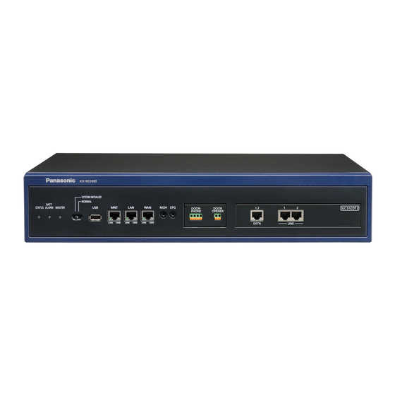
4.2.2 Names and Locations 4.2.2 Names and Locations Front Back C D E F G H Inside STATUS Indicator MASTER Indicator System Mode Switch USB Port MNT Port LAN Port WAN Port MOH Port Doorphone Slot Free Slot BATT ALARM Indicator Pager Port Power Switch Earth Terminal... -
Page 62: Opening/Closing The Top Cover
4.2.3 Opening/Closing the Top Cover 4.2.3 Opening/Closing the Top Cover Opening the Top Cover CAUTION When opening the top cover, the power switch must be turned off. Confirm that the power switch is turned off. Power Switch Note In order to turn off the PBX’s power, a system shutdown using Web Maintenance Console must first be performed. -
Page 63: Closing The Top Cover
4.2.3 Opening/Closing the Top Cover Slide the top cover then lift it off. Remove the support bar from the PBX. Closing the Top Cover Place the support bar onto the PBX. Installation Manual... - Page 64 4.2.3 Opening/Closing the Top Cover Place the top cover onto the PBX. Then slide the top cover until it closes properly. Turn the screws clockwise to tighten. CAUTION For safety reasons, close the top cover and tighten the screws before operating the PBX. Installation Manual...
-
Page 65: Frame Earth Connection
4.2.4 Frame Earth Connection 4.2.4 Frame Earth Connection Loosen the screw. Screw Insert an earthing wire (user-supplied). Tighten the screw. Earthing wire Connect the earthing wire to earth. To earth WARNING • Proper earthing (connection to earth) is very important to reduce the risk to the user of electrocution or to protect the PBX from the bad effects of external noise in the case of a lightning strike. -
Page 66: Installing/Removing The Optional Service Cards
4.2.5 Installing/Removing the Optional Service Cards 4.2.5 Installing/Removing the Optional Service Cards CAUTION • Before touching the product (PBX, cards, etc.), discharge static electricity by touching ground or wearing an earthing strap. Failure to do so may cause the PBX to malfunction due to static electricity. •... - Page 67 4.2.5 Installing/Removing the Optional Service Cards Insert the screws into the holes on the card, and tighten the screws to secure the card. Screws Removing a DSP Card Installed in the DSP Card Slot Loosen and remove the screws. Screws Installation Manual...
- Page 68 4.2.5 Installing/Removing the Optional Service Cards Holding the rear end of the card, pull the card in the direction of the arrows. Installation Manual...
- Page 69 4.2.5 Installing/Removing the Optional Service Cards Installing the Fax Card in the Fax Card Slot Position the FAX card in the FAX card slot. Then, holding the card firmly in place, lower the rear end so that the holes of the card are aligned with the screw holes. Insert the screws into the holes on the card, and tighten the screws to secure the card.
- Page 70 4.2.5 Installing/Removing the Optional Service Cards Removing a Fax Card Installed in the Fax Card Slot Loosen and remove the screws. Screws Holding the rear end of the card, pull the card in the direction of the arrows. Installation Manual...
- Page 71 4.2.5 Installing/Removing the Optional Service Cards Installing an Optional Service Card in the Free Slot You can install one of the SLC2/LCOT2, SLC2/BRI4, SLC2/PRI30 or SLC2/PRI23 card. Some of the optional service cards require DIP switch settings which must be done before installing the card. For details, refer to the description of each optional service card in "4.5 Physical Trunk and Extension Cards"...
- Page 72 4.2.5 Installing/Removing the Optional Service Cards Position the card in the open slot, making sure that the tabs on the both sides of the card fit into place. Then, holding the card firmly in place, lower the rear end so that the holes of the card are aligned with the screw holes.
- Page 73 4.2.5 Installing/Removing the Optional Service Cards Insert the screws into the holes on the card, and tighten the screws to secure the card. Screws Connect cables to appropriate ports of the card. For details about pin assignments, refer to the appropriate section in "4.5 Physical Trunk and Extension Cards".
- Page 74 4.2.5 Installing/Removing the Optional Service Cards Removing an Optional Service Card from the Free Slot Loosen and remove the screws. Screws Holding the rear end of the card, pull the card in the direction of the arrows. Installation Manual...
- Page 75 4.2.5 Installing/Removing the Optional Service Cards Installing the DOORPHONE Card in the Doorphone Slot Remove the front cover plate for the Doorphone Slot. Screw Installation Manual...
- Page 76 4.2.5 Installing/Removing the Optional Service Cards Position the card in the open slot, making sure that the tabs on the both sides of the card fit into place. Then, holding the card firmly in place, lower the rear end so that the holes of the card are aligned with the screw holes.
- Page 77 4.2.5 Installing/Removing the Optional Service Cards Insert the screws into the holes on the card, and tighten the screws to secure the card. Screws Connect cables to appropriate ports of the card. For details about pin assignments, refer to "4.6.1 DOORPHONE Card (KX-NS0161)" and "4.8 Connecting to a Doorphone, Door Opener, and/or External Sensor".
- Page 78 4.2.5 Installing/Removing the Optional Service Cards Removing the DOORPHONE Card from the Doorphone Slot Loosen and remove the screws. Screws Holding the rear end of the card, pull the card in the direction of the arrows. Installation Manual...
-
Page 79: Installing/Removing The Storage Memory Card
4.2.6 Installing/Removing the Storage Memory Card 4.2.6 Installing/Removing the Storage Memory Card Upgrading from the Initially Installed Storage Memory Card To increase Voice Mail recording time, you can install an optional Storage Memory Card. For details about optional Storage Memory Cards, refer to "4.3.2 Storage Memory Card (installed by default), Storage Memory S Card (KX-NS0135), Storage Memory M Card (KX-NS0136), Storage Memory L Card (KX-NS0137)". - Page 80 To prevent data leakage, render the Storage Memory Card physically unusable before disposal. Notice • Use only the Storage Memory Card included with the PBX, or a Panasonic optional upgrade Storage Memory Card. • The Storage Memory Card must be inserted in the Storage Memory Card slot of the mother board before startup.
- Page 81 4.2.6 Installing/Removing the Storage Memory Card Remove the Storage Memory Card installed in the slot on the mother board. Insert the new Storage Memory Card into the slot on the mother board. Place the cover as shown below. Installation Manual...
- Page 82 4.2.6 Installing/Removing the Storage Memory Card Turn the screw clockwise to tighten. Screw Installation Manual...
-
Page 83: Types Of Connectors
4.2.7 Types of Connectors 4.2.7 Types of Connectors Connector Type Pin Number Used for • Mother board RJ45 • SLC2/LCOT2 (KX-NS0180) • SLC2/BRI4 (KX-NS0280) • SLC2/PRI30 (KX-NS0290CE) • SLC2/PRI23 (KX-NS0290) (Twisted pair cable) • DOORPHONE (KX-NS0161) 4-pin 2-pin Terminal Terminal Block Block •... -
Page 84: Attaching A Ferrite Core
4.2.8 Attaching a Ferrite Core 4.2.8 Attaching a Ferrite Core A ferrite core must be attached when an RJ45 connector is connected to the SLC2/PRI30, SLC2/PRI23 or SLC2/BRI4 card. For the SLC2/PRI23 and SLC2/PRI30 Cards For the cable to connect to the ISDN Primary Rate Interface port, wrap the cable once around the ferrite core, then close the case of the ferrite core. -
Page 85: 19-Inch Rack Mounting
4.2.9 19-inch Rack Mounting 4.2.9 19-inch Rack Mounting WARNING • Be careful not to drop any components. Dropping components may damage them or cause an injury. • When mounting the PBX on a 19-inch rack, only use the 19-inch rack mounting equipment (attachment bracket, screws) included with the PBX. -
Page 86: Placing The Pbx On A Desktop
4.2.10 Placing the PBX on a Desktop 4.2.10 Placing the PBX on a Desktop When placing the PBX on a desktop, make sure to follow these instructions. WARNING Be careful not to drop any components. Dropping components may damage them or cause an injury. -
Page 87: Wall Mounting
4.2.11 Wall Mounting 4.2.11 Wall Mounting The PBX can be mounted on a concrete wall using the optional wall mounting kit. WARNING • Make sure that the wall that the unit will be attached to is strong enough to support approximately 4 times the weight of the unit. - Page 88 4.2.11 Wall Mounting Wall Mounting Procedures Measure the actual space as indicated below to mark the 4 screw positions on the wall. Install 4 anchor plugs in the wall and drive in 4 screws (A) leaving a gap of 5 mm between the screw head and the wall. Installation procedure for concrete walls.
- Page 89 4.2.11 Wall Mounting Place the PBX onto the wall, making sure that the guide holes hook onto the screw heads. CAUTION When placing the PBX onto the wall, make sure that the arrows on the metal brackets are pointing upward. If the arrows are not pointing upward, the PBX may fall, resulting in injury. The following illustrations are bad examples of wall mounting.
- Page 90 4.2.11 Wall Mounting Slide the PBX down into the guide holes. Guide Hole Fully tighten all 4 screws (A). Drive the screw to this point. Installation Manual...
-
Page 91: Surge Protector Installation
4.2.12 Surge Protector Installation 4.2.12 Surge Protector Installation CAUTION Performing surge protection is essential. Make sure to follow the instructions in this section. Overview A massive electrical surge can be caused if lightning strikes a telephone cable 10 m above ground, or if a telephone line comes into contact with a power line. - Page 92 4.2.12 Surge Protector Installation Outside Installation (Main Building) Surge Protector Trunk (Another Building) Trunk Extn. Terminal Board Surge Extn. Protector Extn. Extn. Earth Extn.: Extension Line If you install an extension outside of the building, the following precautions are recommended: Install the extension wire underground.
- Page 93 4.2.12 Surge Protector Installation Connect the earth rod to the surge protector using an earthing wire with a cross-sectional area of at least 1.3 mm Bury the earth rod near the protector. The earthing wire should be as short as possible. The earthing wire should run straight to the earth rod.
-
Page 94: The Mother Board And Expansion Cards
4.3.1 Mother Board 4.3 The Mother Board and Expansion Cards 4.3.1 Mother Board Function The mother board is the preinstalled processing board with activation keys for CA Basic-Express for 1022 users, use of 8 IP-PT, and 2 Unified Messaging ports. The Virtual Cards (trunk/extension) can be installed in Virtual Slots of the mother board and can be activated with the activation keys. -
Page 95: Pin Assignments
4.3.1 Mother Board Note • Make sure to use the MNT port for PC connection, and the LAN port for LAN connection. • The maximum length of the CAT 5/CAT 5e cables to be connected to the mother board is 100 m. •... -
Page 96: Led Indications
4.3.1 Mother Board LED Indications Indication Colour Description STATUS Green PBX status indication • OFF: Power Off • ON: Power On and running • Flashing: Starting up/Logging in Amber PBX status indication • ON: Ready to shutdown • Flashing: Shutting down PBX status indication •... - Page 97 4.3.1 Mother Board Indication Colour Description LINK Green Link status indication • OFF: Off-line • ON: Linked normally • Flashing: In communication 1000 Green/ Data transmission speed indication Yellow • OFF: 10 Mbps • Yellow ON: 100 Mbps • Green ON: 1000 Mbps The WAN Port is not used with PCMPR Software Version 001.10000.
-
Page 98: Storage Memory Card (Installed By Default), Storage Memory S Card (Kx-Ns0135), Storage Memory M Card (Kx-Ns0136), Storage Memory L Card (Kx-Ns0137)
4.3.2 Storage Memory Card (installed by default), Storage Memory S Card (KX-NS0135), Storage Memory M Card (KX- NS0136), Storage Memory L Card (KX-NS0137) 4.3.2 Storage Memory Card (installed by default), Storage Memory S Card (KX-NS0135), Storage Memory M Card (KX-NS0136), Storage Memory L Card (KX-NS0137) Function Storage Memory Card... -
Page 99: Dsp S Card (Kx-Ns0110), Dsp M Card (Kx-Ns0111), Dsp L Card (Kx-Ns0112)
4.3.3 DSP S Card (KX-NS0110), DSP M Card (KX-NS0111), DSP L Card (KX-NS0112) 4.3.3 DSP S Card (KX-NS0110), DSP M Card (KX-NS0111), DSP L Card (KX-NS0112) Function A DSP card is a digital signal processor card with DSP resources that can be used for VoIP calls, conferences, the Unified Messaging feature, and the DISA/OGM feature. - Page 100 4.3.3 DSP S Card (KX-NS0110), DSP M Card (KX-NS0111), DSP L Card (KX-NS0112) DSP Card Type Number of Resources DSP M DSP L IP Address Information Either 1 or 2 IP addresses must be assigned to each DSP card, depending on the type of DSP card. You can assign IP addresses to the DSP cards during Easy Setup Wizard or through system programming.
-
Page 101: Fax Card (Kx-Ns0106)
4.3.4 FAX Card (KX-NS0106) 4.3.4 FAX Card (KX-NS0106) Function 1-channel fax server. To be mounted on the mother board. Screws inside FAX Card Accessories and User-supplied Items Accessories (included): Screws ´ 3 User-supplied (not included): none Note When installing or removing the FAX card, do not put pressure on any parts of the mother board. Doing so may result in damage to the PBX. -
Page 102: Virtual Cards
Also supports T.38 protocol. Virtual 32-Channel VoIP Extension Virtual Card for 32 IP-PTs (KX-NT300 series and KX-NT265 Card (V-IPEXT32) [software version 2.00 or later only]). Compliant with Panasonic proprietary protocol, and ITU-T G.729A, G.711 and G.722 codec methods. Virtual 32-Channel SIP Extension Virtual Card for 32 third party SIP phones. - Page 103 4.4 Virtual Cards Example: Virtual Cards in the Virtual Slots of the PBX V-SIPGW16 V-IPGW16 V-IPEXT32 V-SIPEXT32 V-IPCS4 V-UTEXT32 V-SIPGW16 V-IPGW16 V-IPEXT32 V-SIPEXT32 V-IPCS4 V-UTEXT32 V-SIPGW16 V-IPGW16 V-IPEXT32 V-SIPEXT32 V-IPCS4 V-UTEXT32 V-SIPGW16 V-IPGW16 V-IPEXT32 V-SIPEXT32 V-IPCS4 V-UTEXT32 Virtual Slots Mother Board Installation Manual...
-
Page 104: Physical Trunk And Extension Cards
4.5.1 SLC2/LCOT2 Card (KX-NS0180) 4.5 Physical Trunk and Extension Cards 4.5.1 SLC2/LCOT2 Card (KX-NS0180) Function A combination card including: • 2 analogue trunk ports with Caller ID (FSK/FSK with Call Waiting Caller ID [Visual Caller ID]/DTMF). One port is a power failure transfer (PFT) port. •... - Page 105 4.5.1 SLC2/LCOT2 Card (KX-NS0180) RJ45 Connector for Single Line Telephone Extension Use Signal Name Function Reserved – Ring B RA TA Ring A Tip A Tip B Reserved – Installation Manual...
-
Page 106: Slc2/Bri4 Card (Kx-Ns0280)
4.5.2 SLC2/BRI4 Card (KX-NS0280) 4.5.2 SLC2/BRI4 Card (KX-NS0280) Function A combination card including: • 4 ISDN Basic Rate Interface ports. • 2 extension ports with Caller ID (FSK) for SLTs. EURO-ISDN/ETSI compliant. RJ45 for SLT RJ45 (LINE 1 to LINE 4) To SLT LEDs To NT1/ Extension... - Page 107 4.5.2 SLC2/BRI4 Card (KX-NS0280) Pin Assignments RJ45 Connector for Trunk Use Signal Name Level [V] Function Reserved – – Transmit data 1 Receive data 1 Receive data 2 Transmit data 2 Reserved – – RJ45 Connector for Extension Use Signal Name Level [V] Function Reserved...
- Page 108 4.5.2 SLC2/BRI4 Card (KX-NS0280) LINE LED Pattern Master Layer 1 Layer 2 LED Pattern Clock Layer 1: ON (Synchronous) Layer 2: ON (Link established)/OFF (Link not established) Master Clock: ON (Master)/OFF (Slave) Maximum Cabling Distance of ISDN DSU Connection The maximum length of the cable that connects the DSU and the PBX is shown below: Point-to-Point CAT 5: Under 1000 m Installation Manual...
- Page 109 4.5.2 SLC2/BRI4 Card (KX-NS0280) Maximum Cabling Distance of ISDN Terminal Equipment (TE) Connection The maximum length of the extension cable that connects the PBX and the TE is shown below: Point-to-Point CAT 5: Under 1000 m Installation Manual...
-
Page 110: Slc2/Pri30 Card (Kx-Ns0290Ce)
4.5.3 SLC2/PRI30 Card (KX-NS0290CE) 4.5.3 SLC2/PRI30 Card (KX-NS0290CE) Function A combination card including: • 1 ISDN Primary Rate Interface port (30B channels). • 2 extension ports with Caller ID (FSK) for SLTs. EURO-ISDN/ETSI compliant. RJ45 To SLT To NT1/ Extension LEDs LEDs Accessories and User-supplied Items... - Page 111 4.5.3 SLC2/PRI30 Card (KX-NS0290CE) Pin Assignments RJ45 Connector for Trunk Use Signal Name Level [V] Function Receive data (+) Receive data (-) Reserved – – Transmit data (-) Transmit data (+) Reserved – – RJ45 Connector for Extension Use Signal Name Level [V] Function Transmit data (-)
- Page 112 4.5.3 SLC2/PRI30 Card (KX-NS0290CE) Indication Colour Description RAI signal status indication • OFF: Normal • ON: Alarm • Flashing (60 times per minute): Alarm (Clock Master) AIS status indication • OFF: Normal • ON: Alarm SYNC Green Synchronisation status indication •...
-
Page 113: Slc2/Pri23 Card (Kx-Ns0290)
4.5.4 SLC2/PRI23 Card (KX-NS0290) 4.5.4 SLC2/PRI23 Card (KX-NS0290) Function A combination card including: • 1 ISDN Primary Rate Interface port (23B channels). • 2 extension ports with Caller ID (FSK) for SLTs. NI (North American standard ISDN protocol) compliant. RJ45 To SLT To NT1/ Extension LEDs... - Page 114 4.5.4 SLC2/PRI23 Card (KX-NS0290) Pin Assignments RJ45 Connector for Trunk Use Signal Name Level [V] Function Receive data (+) Receive data (-) Reserved – – Transmit data (-) Transmit data (+) Reserved – – RJ45 Connector for Extension Use Signal Name Level [V] Function Transmit data (-)
- Page 115 4.5.4 SLC2/PRI23 Card (KX-NS0290) Indication Colour Description RAI signal status indication • OFF: Normal • ON: Alarm (Clock Slave) • Flashing (60 times per minute): Alarm (Clock Master) AIS status indication • OFF: Normal • ON: Alarm SYNC Green Synchronisation status indication •...
-
Page 116: The Doorphone Card
4.6.1 DOORPHONE Card (KX-NS0161) 4.6 The Doorphone Card 4.6.1 DOORPHONE Card (KX-NS0161) Function A doorphone card for 1 doorphone, 1 door opener, and 1 external sensor. 4-pin 2-pin To doorphone/ external sensor To door opener Accessories and User-supplied Items Accessories (included): Screws ´ 2 User-supplied (not included): Copper wire Note For details about connecting to a doorphone and/or door opener, refer to "4.8 Connecting to a Doorphone,... - Page 117 4.6.1 DOORPHONE Card (KX-NS0161) External Sensor Power to the external sensor is provided from the DOORPHONE card and must be grounded through the DOORPHONE card as indicated in the diagram below. A pair of "sensor" and "common" lines are connected to the DOORPHONE card for each external sensor.
-
Page 118: Connection Of Slts
4.7.1 Maximum Cabling Distances of the Extension Wiring (Twisted Cable) 4.7 Connection of SLTs 4.7.1 Maximum Cabling Distances of the Extension Wiring (Twisted Cable) Cable Maximum Distance ø 0.4 mm: 698 m ø 0.5 mm: 1128 m ø 0.6 mm: 1798 m CAT 5: 1128 m... -
Page 119: Connecting To A Doorphone, Door Opener, And/Or External Sensor
4.8 Connecting to a Doorphone, Door Opener, and/or External Sensor 4.8 Connecting to a Doorphone, Door Opener, and/ or External Sensor The PBX supports 1 each of a doorphone, a door opener, and an external sensor. Note Doorphones, door openers, and external sensors are user-supplied. Maximum Cabling Distance Cable Maximum Distance... - Page 120 4.8 Connecting to a Doorphone, Door Opener, and/or External Sensor Note for KX-T7765 Users When loosening/tightening the screw, do not scratch the cabinet wall with the driver shaft. Cabinet Wall Pass the wires through the hole in the base cover, and attach the base cover to a wall using 2 screws. Screw To 4-pin terminal block Note...
- Page 121 4.8 Connecting to a Doorphone, Door Opener, and/or External Sensor Connection Use 4-pin and 2-pin terminal blocks (included with the card) for connection. While pressing on the orange tab at the bottom of the terminal block using a screwdriver, insert the wire into the upper hole as shown below.
-
Page 122: Connection Of Peripherals
4.9 Connection of Peripherals 4.9 Connection of Peripherals Maximum Distance USB Memory Device Maximum Distance 100 m Cable Maximum Distance ø 0.4 mm: 10 m ø 0.5 mm: 10 m USB Port ø 0.6 mm: 10 m CAT 5/ MNT Port 10 m CAT 5e: Cable... - Page 123 4.9 Connection of Peripherals Pin Assignments for 1000BASE-T Input (I)/ Signal Name Function Output (O) TRD0 (+) Transmit and receive data 0 (+) TRD0 (-) Transmit and receive data 0 (-) TRD1 (+) Transmit and receive data 1 (+) TRD2 (+) Transmit and receive data 2 (+) TRD2 (-) Transmit and receive data 2 (-)
- Page 124 4.9 Connection of Peripherals Make sure that both connector cases (frame ground) of the RS-232C cross cable (shielded cable) are conductive. If they are not conductive, make sure that both connector cases of the cable are firmly connected. If this is not possible, connect the frame of the PBX to the frame of the PC/Printer using an earthing wire in order to prevent difference in the electrical potentials.
- Page 125 4.9 Connection of Peripherals For connecting a printer/PC with a 25-pin RS-232C connector PBX (9-pin) Printer/PC (25-pin) Circuit Type Signal Signal Circuit Type Pin No. Pin No. (EIA) Name Name (EIA) RD (RXD) SD (TXD) RD (RXD) ER (DTR) SD (TXD) ER (DTR) DR (DSR) RS (RTS)
- Page 126 4.9 Connection of Peripherals • Maximum current: 500 mA For details about backing up and restoring using a USB memory device, refer to "6.1 Tool—System Data Backup to USB" in the PC Programming Manual. Note Do not use a USB hub when connecting a USB memory device to the PBX. Using a UPS A UPS is a device that supplies power for several minutes to a connected device when a power failure occurs.
-
Page 127: Lan Connection
4.10.1 LAN Connection for the Main Unit 4.10 LAN Connection 4.10.1 LAN Connection for the Main Unit Connecting the Main Unit to the LAN The PBX is equipped with a LAN port for connecting to a LAN so that IP telephones (IP-PTs, IP softphones, SIP phones), IP-CSs, PCs and a CTI Server can be connected on a private IP network. - Page 128 4.10.1 LAN Connection for the Main Unit Connection for 1000BASE-T Switching Hub PBX (LAN Port) Pin No. Pin No. Signal Name Signal Name TRD0 (+) TRD0 (+) TRD0 (-) TRD0 (-) TRD1 (+) TRD1 (+) TRD2 (+) TRD2 (+) TRD2 (-) TRD2 (-) TRD1 (-) TRD1 (-)
-
Page 129: Lan Connections For Ip Telephones
4.10.2 LAN Connections for IP Telephones 4.10.2 LAN Connections for IP Telephones When an IP telephone is connected to the LAN and power is supplied for the first time, you will be prompted to set network parameters. The network parameters must be set for the IP telephone before it can be used. Refer to "5.8 Assigning Networking Information to IP Telephones"... - Page 130 4.10.2 LAN Connections for IP Telephones Connecting an AC Adaptor to an IP Telephone IP-PTs and some SIP phones comply with the IEEE 802.3af Power-over-Ethernet (PoE) standard. If PoE is available on your network, these IP telephones can receive the necessary power supply from the network through the network cable.
- Page 131 4.10.2 LAN Connections for IP Telephones Example: KX-NT346 To a PC Ethernet Straight Cable Installation Manual...
-
Page 132: Power Failure Ports
4.11 Power Failure Ports 4.11 Power Failure Ports When the power supply to the PBX fails, power failure transfer (PFT) will switch from the current connection to the Power Failure Connection. Refer to "5.5.2 Power Failure Transfer" in the Feature Guide for further information. -
Page 133: Starting The Pbx
4.12 Starting the PBX 4.12 Starting the PBX WARNING Make sure that the AC outlet is properly earthed, then securely connect the 3-pin AC plug including the earthed pin. CAUTION • Use only the AC power cord included with the PBX. •... -
Page 134: Connecting The Ac Power Cord
• For information about the installation of an UPS, refer to the documentation of your UPS. • For information about the recommended UPS, ask your local Panasonic dealer. Connect the UPS to the USB port of the PBX. Installation Manual... - Page 135 4.12 Starting the PBX Note When connecting the UPS, use only the USB cable included with the UPS and do not use USB hubs to connect the UPS and the PBX. To UPS Follow the instructions in the documentation of the UPS to setup and start the UPS. System Initialisation Procedure Notice When a UPS is connected, make sure it is started as instructed in the documentation for the UPS.
- Page 136 4.12 Starting the PBX All data, except for system prompts and activation key files, will be erased. Data that is erased includes Unified Messaging data, call logs, etc. The settings for the PBX as well as all optional service cards will be initialised to their default values.
-
Page 137: Programming With Web Maintenance Console
Section 5 Programming with Web Maintenance Console This section describes the installation procedure, structure, and functions of the Web Maintenance Console for programming IP telephones and the PBX. Further information on programming the PBX for use with SIP trunks and a VoIP network is included. Installation Manual... -
Page 138: Overview Of Web Maintenance Console
5.1 Overview of Web Maintenance Console 5.1 Overview of Web Maintenance Console Web Maintenance Console is designed to serve as an overall system programming reference for the PBX. You can programme and control the PBX over an IP network using Web Maintenance Console. This section describes programming basic items using Web Maintenance Console. -
Page 139: Pc Connection
5.2 PC Connection KX-NS1000 has 3 physical ports for PC and LAN connections. A default IP address is assigned to each port. A PC connect to the PBX either directly or over a LAN using the appropriate method for the port being used. -
Page 140: Connection Via Internet
5.2 PC Connection Note For details about connecting a switching hub to the PBX, refer to "4.10.1 LAN Connection for the Main Unit". Connection via Virtual Private Network (VPN) Router LAN Port Router Switching Hub Notice To access the PBX via VPN, the PC must be in the same VPN. Note For details about connecting a switching hub to the PBX, refer to "4.10.1 LAN Connection for the Main Unit". - Page 141 5.2 PC Connection Note For details about connecting a switching hub to the PBX, refer to "4.10.1 LAN Connection for the Main Unit". Installation Manual...
-
Page 142: Starting Web Maintenance Console
5.3 Starting Web Maintenance Console 5.3 Starting Web Maintenance Console System Requirements Required Operating System • Microsoft Windows XP, Windows Vista Business, or Windows 7 Professional operating system ® ® ® Recommended Display Settings • Screen resolution: XGA (1024 ´ 768) •... - Page 143 Access Web Maintenance Console: MNT Port Connection: Launch your Web browser and in the address bar, enter the following address exactly as shown: http://kx-ns1000. Note Be sure to include the period at the end as shown. LAN or VPN Connection: Launch your Web browser and input the IP address of the PBX followed by the Web Maintenance Console port number into the address bar.
- Page 144 5.3 Starting Web Maintenance Console "27.1 Network Service—IP Address/Ports—Basic Settings", and the port in "27.2.3 Network Service —Server Feature—HTTP" in the PC Programming Manual. The Web Maintenance Console login screen is displayed. Log in with the Installer level account name and the default Installer level account password to launch the Easy Setup Wizard.
-
Page 145: Programming The Pbx
5.4.1 Easy Setup Wizard 5.4 Programming the PBX 5.4.1 Easy Setup Wizard In the Easy Setup Wizard, you will set up the mandatory settings required for the PBX. When you log in to Web Maintenance Console for a PBX that is in its initialised, factory default state, the Easy Setup Wizard for that PBX will launch automatically. - Page 146 5.4.1 Easy Setup Wizard Click Next. When not using a DHCP server: Select Use the following IP address. Enter an IP address , Subnet Mask , and Default Gateway . (The default gateway may not need to be specified depending on your network configuration.) Select Use the following DNS server address.
- Page 147 If an external DHCP server is in use, it must be able to use a "client identifier" option specified by RFC 2131. • If an external DHCP server is in use, the KX-NS1000 DHCP Server feature must be disabled. • The PBX will not start properly if IP addresses cannot be assigned automatically by the DHCP server when the PBX has been set to obtain IP addresses automatically.
-
Page 148: Enabling The Dhcp Server Feature
5.4.2 Enabling the DHCP Server Feature • During a long programming session, it is highly recommended that you periodically save the system data to the Storage Memory Card. If the PBX undergoes a sudden power failure or if the system is reset for some reason, all the system data in RAM will be lost. -
Page 149: Installing The Virtual Ip Cards To The Pbx
5.4.5 Configuration of the Activation Keys 5.4.3 Installing the Virtual IP Cards to the PBX Click Setup ® PBX Configuration ® Configuration ® Slot. Click Virtual. Click on the name of the desired card. From the Total number of cards drop-down list, select the desired number of cards. - Page 150 5.4.5 Configuration of the Activation Keys Similarly, you can programme how many IP softphone(s) can be used through the IP Softphone/IP Proprietary Telephone activation key. By default, only IP softphone(s) can be used through the IP Softphone/IP Proprietary Telephone activation key. Click Setup ®...
-
Page 151: Programming A One-Look Network
5.5 Programming a One-look Network 5.5 Programming a One-look Network The Add Site Wizard, which is run from the Home Screen of the Master unit, will add other KX-NS1000 PBXs connected to the private IP network to your One-look network as Slave units. - Page 152 5.5 Programming a One-look Network Slave (When Slave unit power is Slave (When Slave unit power is Master turned on before Master unit) turned on after Master unit) Operation MASTER LED Operation MASTER LED Operation MASTER LED Power On Amber (Flashing) Log in Amber...
-
Page 153: Programming A H.323 Qsig Network
5.6.1 Assigning the Hunt Pattern 5.6 Programming a H.323 QSIG Network There are 2 methods to programme the Virtual 16-Channel VoIP Gateway Card (V-IPGW16 card) to establish VoIP communications between PBXs at different locations, as follows: PBX code method The caller dials the unique PBX code of the PBX to which the called party is connected, in addition to the destination number. -
Page 154: Programming The Address Translation Table
5.6.2 Programming the Address Translation Table Note For more details about hunt pattern assignment, refer to "9.11.2 PBX Configuration—Configuration—Slot —Shelf Property - Virtual IP Gateway—Hunt Pattern" in the PC Programming Manual. 5.6.2 Programming the Address Translation Table The function of an address translation table in a VoIP network is to provide 2-way translation of telephone numbers and IP addresses . - Page 155 5.6.2 Programming the Address Translation Table Click Setup ® PBX Configuration ® Configuration ® Slot. Click System Property. Click the V-IPGW tab. Click DN2IP. When using the PBX code method: In the Leading Number cell, type the remote PBX code and starting digit of destination extension. When using the extension number method: In the Leading Number cell, type the remote PBX code and starting digit of destination extension.
-
Page 156: Programming The Network Settings
5.6.3 Programming the Network Settings 5.6.3 Programming the Network Settings For successful operation of a VoIP network using the V-IPGW16 card, network settings for the PBX at each location must be programmed appropriately. For a detailed discussion of related features, refer to the Feature Guide. - Page 157 5.6.3 Programming the Network Settings Click Setup ® PBX Configuration ® System. Click Numbering Plan. Click Main. Click the Features tab. In the TIE Line Access cell, type the dialling number. Click OK. Click Setup ® PBX Configuration ® Private Network.
- Page 158 5.6.3 Programming the Network Settings Confirm that all V-IPGW16 cards are set to OUS. Note When a V-IPGW16 card is installed, 8 ports are available for the card. Click Setup ® PBX Configuration ® CO & Incoming Call. Click CO Line Settings. Type the CO Name and assign an unused Trunk Group Number to be used for all IP trunks.
- Page 159 5.6.3 Programming the Network Settings Click Setup ® PBX Configuration ® Configuration ® Slot. Click Virtual ® V-IPGW16. Move the mouse pointer over the installed V-IPGW16 card to display the menu of options, and click Ins. Repeat step c for each installed V-IPGW16 card until all V-IPGW16 cards are INS.
-
Page 160: Programming Sip Trunks
5.7 Programming SIP Trunks 5.7 Programming SIP Trunks The Virtual 16-Channel SIP Trunk Card (V-SIPGW16) is a virtual trunk card which is designed to be easily integrated into an Internet Telephony Service provided by an ITSP (Internet Telephony Service Provider). Various settings can be programmed for each virtual SIP gateway port. - Page 161 5.7 Programming SIP Trunks Manual programming is compulsory for the following parameters: • User Name: Specifies the user name (SIP Account) provided by the SIP provider. (Max. 64 characters) • Authentication ID: Specifies the authentication ID required for registration with the SIP server. (Max. 64 characters) •...
-
Page 162: Assigning Networking Information To Ip Telephones
5.8.1 Assigning IP Addressing Information 5.8 Assigning Networking Information to IP Telephones 5.8.1 Assigning IP Addressing Information The IP telephone’s IP address, subnet mask address and default gateway address, and the PBX’s IP address must be assigned to the IP telephone before it can be used on the network. This IP addressing information can be assigned in the following ways: For IP-PTs •... - Page 163 5.8.1 Assigning IP Addressing Information KX-NT300 series (except KX-NT321) To start programming SETUP Supply power to the IP-PT. Press "SETUP" when it is displayed. To enter the IP address of the PBX Software version 2.00 or later only Select "PBX". ENTER Select "PBX IP Address".
- Page 164 5.8.1 Assigning IP Addressing Information KX-NT321 To start programming Supply power to the IP-PT. Press PROGRAM while "Searching" is displayed. To enter the IP address of the PBX Select "PBX IP Press SP-PHONE. Select "PBX". Press SP-PHONE. Select "Primary Address". PBX".
- Page 165 5.8.1 Assigning IP Addressing Information KX-NT265 (Software version 2.00 or later only) To start programming PROG. Supply power to the IP-PT. Press PROGRAM while "Searching" is displayed. To enter the IP address of the PBX HOLD PBX IP Address Press VOLUME Press SP-PHONE Press SP-PHONE.
- Page 166 5.8.1 Assigning IP Addressing Information • Not using a DHCP server (DHCP Server feature or an external DHCP server) when the IP-PT is on the same LAN as the PBX Only the PBX’s IP address can be assigned automatically to the IP-PT in the process of being registered to the PBX.
- Page 167 5.8.1 Assigning IP Addressing Information Continued from previous page To set VLAN parameters To the VLAN settings Return to the Menu screen. To end programming STORE The IP-PT will reboot and can then be registered to the PBX. Press "STORE". Return to the Menu screen.
- Page 168 5.8.1 Assigning IP Addressing Information KX-NT321 To start programming Supply power to the IP-PT. Press PROGRAM while "Searching" is displayed. To set the IP address of the IP-PT Select "Network". Press SP-PHONE. Select "DHCP (Disable)". Press SP-PHONE twice. IP Address* Press SP-PHONE.
- Page 169 5.8.1 Assigning IP Addressing Information Continued from previous page To set VLAN parameters To the VLAN settings To end programming The IP-PT will reboot and can then be registered to the PBX. Press STORE. Valid IP address range: "1.0.0.0" to "223.255.255.255" Valid subnet mask address range: "0–255.0–255.0–255.0–255"...
- Page 170 5.8.1 Assigning IP Addressing Information KX-NT265 (Software version 2.00 or later only) To start programming PROG. Supply power to the IP-PT. Press PROGRAM while "Searching" is displayed. To set the IP address of the IP-PT Press VOLUME to Press SP-PHONE. Press VOLUME to Press SP-PHONE select "Network".
- Page 171 5.8.1 Assigning IP Addressing Information • Not using a DHCP server (DHCP Server feature or an external DHCP server) when the IP-PT is on a remote office LAN All of the IP addressing information must be assigned manually. Follow the procedure below to assign the IP addressing information. If you need to set VLAN parameters, follow the procedure described in "5.8.2 Setting VLAN Parameters"...
- Page 172 5.8.1 Assigning IP Addressing Information KX-NT300 series (except KX-NT321) To start programming SETUP Supply power to the IP-PT. Press "SETUP" when it is displayed. To set the IP address of the IP-PT Select "Network". ENTER Select "Disable" Select "IP Address". ENTER for DHCP setting.
- Page 173 5.8.1 Assigning IP Addressing Information Continued from previous page To enter the IP address of the Secondary PBX (optional for software version 2.00 or later only) PBX IP Address Select "Secondary PBX". ENTER ENTER To set VLAN parameters To the VLAN settings Return to the Menu screen.
- Page 174 5.8.1 Assigning IP Addressing Information KX-NT321 To start programming Supply power to the IP-PT. Press PROGRAM while "Searching" is displayed. To set the IP address of the IP-PT Select "Network". Press SP-PHONE. Select "DHCP (Disable)". Press SP-PHONE twice. IP Address* Press SP-PHONE.
- Page 175 5.8.1 Assigning IP Addressing Information Continued from previous page Press HOLD twice to return to the Menu screen. To set VLAN parameters To the VLAN settings To end programming The IP-PT will reboot and can then be registered to the PBX. Press STORE.
- Page 176 5.8.1 Assigning IP Addressing Information KX-NT265 (Software version 2.00 or later only) To start programming PROG. Supply power to the IP-PT. Press PROGRAM while "Searching" is displayed. To set the IP address of the IP-PT Press VOLUME to Press SP-PHONE. Press VOLUME to Press SP-PHONE select "Network".
- Page 177 Notice Do not perform any other operation rather than following procedure with Web user interface. Otherwise the SIP phone may not work properly. In that case, contact an authorised Panasonic Factory Service Centre. Prepare a configuration file to specify the IP address of the PBX.
- Page 178 5.8.1 Assigning IP Addressing Information Notice • For "xxx.xxx.xxx.xxx:yyy", enter the IP address and port number of the network router which is in a same LAN with the PBX. The router accessed by the SIP phone must have static NAT/NAPT settings enabled so that the packets sent to xxx.xxx.xxx.xxx:yyy to be transferred to the PBX.
- Page 179 Notice When the 2 UT_ACS.cfg files do not match, and if the SIP phone does not work properly, contact an authorised Panasonic Factory Service Centre. For Non-KX-UT Series SIP Phones Using a DHCP server (DHCP Server feature or an external DHCP server) to automate the assignment...
-
Page 180: Setting Vlan Parameters
5.8.2 Setting VLAN Parameters 5.8.2 Setting VLAN Parameters To establish voice communications between IP telephones, the primary ports of the IP telephones and the connected PBX must belong to the same VLAN. Consult your network administrator and obtain the appropriate VLAN ID. - Page 181 5.8.2 Setting VLAN Parameters KX-NT321 After assigning the IP addresses Select "QoS". Press SP-PHONE. Select "VLAN". Press SP-PHONE. Press SP-PHONE. Select "VLAN (Enable)". To set the VLAN ID for the primary port VLAN ID 1–4094 Select "VLAN (Primary)". Press SP-PHONE. Select "VLAN ID".
- Page 182 5.8.2 Setting VLAN Parameters KX-NT265 (Software version 2.00 or later only) After assigning the IP addresses Press VOLUME to Press SP-PHONE. Press VOLUME to Press SP-PHONE. Press VOLUME to select "QoS". select "VLAN". select "VLAN (Enable)". VLAN ID VLAN Priority Press SP-PHONE.
-
Page 183: Setting Diffserv Parameters
5.8.3 Setting Diffserv Parameters 5.8.3 Setting Diffserv Parameters Differentiated Services (DiffServ, or DS) is an IP-based QoS technique used to control QoS of VoIP communications by setting the DS field in the header of IP packets. Consult your network administrator for the appropriate setting values for the DS field. - Page 184 5.8.3 Setting Diffserv Parameters KX-NT321 To start programming Press PROGRAM while Select "QoS". Select "Diffserv". Press SP-PHONE. Press SP-PHONE. "Searching" is displayed. To set the DS field value for the primary port Select "Primary Port". Press SP-PHONE. Select "DS (Enable)". Press SP-PHONE.
- Page 185 5.8.3 Setting Diffserv Parameters KX-NT265 (Software version 2.00 or later only) To start programming PROG. Press PROGRAM while Press VOLUME to Press SP-PHONE. Press VOLUME to Press SP-PHONE. "Searching" is displayed. select "QoS". select "Diffserv". To set the DS field value Diffserv 0.0–7.7 Press VOLUME to...
-
Page 186: Configuration Of Ip Ports
5.8.4 Configuration of IP Ports 5.8.4 Configuration of IP Ports A KX-NT300 series IP-PT user or KX-NT265 IP-PT user can configure the port number of PTAP, DHCP, and FTP ports. Consult your network administrator to check whether the configuration of the IP ports is required. Follow the procedure below to configure the port number of the IP ports. - Page 187 5.8.4 Configuration of IP Ports Continued from previous page To configure the port number of FTP Ports Port No. Select "FTP Server Ctrl Port". ENTER 21, 1024 – 65535 ENTER Port No. Select "FTP Client Ctrl Port". ENTER 1024 – 65535 ENTER Port No.
- Page 188 5.8.4 Configuration of IP Ports KX-NT321 To start programming Password Press PROGRAM while Select "IP Port". Press SP-PHONE. 7678 Press SP-PHONE. "Searching" is displayed. To configure the port number of PTAP Ports Select "PTAP Server". Press SP-PHONE. Select "Primary PBX". Press SP-PHONE.
- Page 189 5.8.4 Configuration of IP Ports Continued from previous page To configure the port number of FTP Ports Port No. 21, 1024 – 65535 Press SP-PHONE. Select "FTP Server Ctrl". Press SP-PHONE. Port No. 1024 – 65535 Select "FTP Client Ctrl". Press SP-PHONE.
- Page 190 5.8.4 Configuration of IP Ports KX-NT265 (Software version 2.00 or later only) To start programming PROG. Password Press PROGRAM while Press VOLUME to Press SP-PHONE. 7678 Press SP-PHONE. "Searching" is displayed. select "IP Port". To configure the port number of PTAP Ports Port No.
- Page 191 5.8.4 Configuration of IP Ports Note If you wish to change the port number back to default, enter 0 as the port number for the desired port. Installation Manual...
-
Page 192: Registering Ip Telephones
5.9.1 Registering IP Telephones 5.9 Registering IP Telephones 5.9.1 Registering IP Telephones After the programming of the PBX and IP telephones is finished (refer to "5.8 Assigning Networking Information to IP Telephones"), the IP telephones must be registered to the PBX. The procedure for registering IP telephones differs according to the IP terminal registration mode specified during the Easy Setup Wizard. - Page 193 5.9.1 Registering IP Telephones Enter an extension number. Note When no extension number is entered in this step, the process will time out and the IP-PT will be registered without an extension number. Press [ENTER] on the IP-PT. Press [PAUSE] or "EXIT" on the IP-PT. For KX-UT Series SIP Phones If networking settings have been completed, when KX-UT series SIP phones are connected to the same network as the PBX, they will be registered automatically as same as when they are registered in Full Automatic...
- Page 194 5.9.1 Registering IP Telephones If the Connection column for the port is INS, click INS, and then click OUS on the dialogue box to change the port’s status. Enter the MAC address of the IP-PT or SIP phone in the IP Phone Registration ID (MAC Address) cell.
- Page 195 5.9.1 Registering IP Telephones For Non-KX-UT Series SIP Phones After connecting non-KX-UT series SIP phones to the PBX over a network, register those IP terminals to the PBX manually. Follow the procedure below for registration. Click Setup ® PBX Configuration ® Configuration ®...
- Page 196 5.9.1 Registering IP Telephones Set passwords for the SIP extensions. Click the cell in the Connection column for each SIP extension you wish to register. The Command Connection screen appears. Click OUS. Enter a password in the Password cell for each SIP extension.
- Page 197 5.9.1 Registering IP Telephones Programme the SIP extension you wish to register. Set the IP address of the PBX, extension number, and password in the corresponding fields for your SIP extension. Send a request from the SIP extension to the PBX for registration.
-
Page 198: De-Registering Ip Telephones
5.9.2 De-registering IP Telephones 5.9.2 De-registering IP Telephones De-registration of IP-PTs or KX-UT Series SIP Phones Make sure the IP Terminal Registration Mode is set to Manual. Click Setup ® PBX Configuration ® Configuration ® Slot ® Site Property ® Main. In the Main tab, select Manual for IP Terminal Registration Mode. - Page 199 5.9.2 De-registering IP Telephones Forced De-registration of IP-PTs or KX-UT Series SIP Phones Follow the steps below to forcibly de-register an IP-PT when normal de-registration was unsuccessful. Click Setup ® PBX Configuration ® Configuration ® Slot. For IP-PTs: Click Virtual ® V-IPEXT32. For KX-UT series SIP phones: Click Virtual ®...
- Page 200 5.9.2 De-registering IP Telephones De-registration of Non-KX-UT Series SIP Phones The de-registration of non-KX-UT series SIP phones is carried out by deleting either the extension number or password registered in the PBX. Click Setup ® PBX Configuration ® Configuration ® Slot. Click Virtual ®...
-
Page 201: Configuration Of Users
5.10 Configuration of Users 5.10 Configuration of Users The system manages information about each user. Before programming other user settings, the following information must be configured for each user: • Extension number • Name • Unified Messaging mailbox • Web Maintenance Console login account (ID and password) Follow the procedure below to efficiently programme basic personal information by adding multiple users with the Add Range feature. - Page 202 5.10 Configuration of Users Installation Manual...
-
Page 203: Troubleshooting
Section 6 Troubleshooting This section provides information on the PBX and telephone troubleshooting. Installation Manual... -
Page 204: Troubleshooting
6.1.1 Installation 6.1 Troubleshooting 6.1.1 Installation PROBLEM PROBABLE CAUSE SOLUTION You cannot make/receive • • DSP card malfunction Replace the corresponding card. calls via an IP network. • • Mother board Replace the mother board (be sure to turn malfunction off the PBX when replacing). - Page 205 6.1.1 Installation PROBLEM PROBABLE CAUSE SOLUTION Extensions (except IP-PT/ • • Extension card Replace the corresponding card. SIP phone) do not operate. malfunction • • Poor connection Take the extension and plug it into the between the PBX and same extension port using a short the extension telephone cord.
-
Page 206: Connection
6.1.2 Connection 6.1.2 Connection Connection between the PBX and an SLT: CAUSE SOLUTION Can you dial The T/R is connected to the D1/D2. Use the correct cord (the an extension? inner 2 wires are for T/R). If a telephone equipped with an A-A1 relay is connected to the PBX, set the A-A1 relay switch of the... -
Page 207: Operation
6.1.3 Operation 6.1.3 Operation PROBLEM PROBABLE CAUSE SOLUTION • • • Cannot set the IP An unusable value is Set an IP address within the valid range. address, subnet mask being set. IP address of the IP-PT/PBX: "1.0.0.0" to address, and PBX IP "223.255.255.255"... - Page 208 6.1.3 Operation PROBLEM PROBABLE CAUSE SOLUTION • • The IP address of the Connect a PC to the MNT port of the PBX PBX for networking has directly and start the Web Maintenance been forgotten. Console using the default IP address of the MNT port, and then confirm the IP address assigned for the LAN port.
-
Page 209: Error Messages
6.1.4 Error Messages 6.1.4 Error Messages When a major system error occurs, an error message is displayed on the IP-PT. For IP-PTs with a single line display (e.g., KX-NT265), only an error code (i.e., ERR XXXX-XXXX) will be displayed. Error Message & IP-PT Activity Probable Cause Solution ERR 1001-0000... - Page 210 6.1.4 Error Messages Error Message & IP-PT Activity Probable Cause Solution ERR 2004-0000 • • IP-PT not registered Check the registration UNREGISTERED TO SERVER status of the IP-PT. Resets and displays error for 5 seconds while starting up. ERR 2005-0000 •...
-
Page 211: Restarting The Pbx
6.1.5 Restarting the PBX 6.1.5 Restarting the PBX If the PBX does not operate properly, restart the PBX using Web Maintenance Console. Before restarting the PBX, try the system feature again to confirm whether there definitely is a problem or not. Note •... - Page 212 6.1.5 Restarting the PBX Example: Extensions Estimated Time for Starting Up 1 PBX 128 KX-UT series SIP phones more than 5 minutes (Stand-alone) 16 PBXs 256 KX-UT series SIP phones more than 15 minutes (One-look network) • PBX functions cannot be used until restarting is complete. The use of a UPS is recommended; even a momentary power failure can result in a long delay as the PBX restarts, requiring the time as shown above.
-
Page 213: Troubleshooting By Error Log
6.1.6 Troubleshooting by Error Log 6.1.6 Troubleshooting by Error Log When a major system error occurs in the PBX, the STATUS indicator on the front of the cabinet turns red, and the system logs the error information. Error Log Display Format Below is the display format of the error log. - Page 214 6.1.6 Troubleshooting by Error Log Item Description Sub Code SMDR: The 8-digit sub code of the relevant hardware (BBWXYYZZ). Web Maintenance Console: The 6-digit sub code of the relevant hardware (WXYYZZ). (The site number of the PBX can be confirmed in the Site column of the Error Log.) •...
-
Page 215: Appendix
Section 7 Appendix This section provides information on using the PBX with a VoIP network, the ports used by the PBX, and PBX Region Suffix Codes and Areas. Installation Manual... -
Page 216: Information About Using An Ip Network
Note Panasonic IP Cell Station (IP-CS) units are also supported by this PBX for communication on a VoIP network. For details, refer to the Quick Installation Guide for the IP-CS. (i) Connection Outline of VoIP Network with Remote Office LAN... -
Page 217: Network Parameters
7.1.1 Using a VoIP Network with the PBX (ii) Connection Outline of VoIP Network with PBX in Other Network Router Headquarters Headquarters PBX with V-IPGW card/ V-SIPGW card Switching Hub Private IP Network Router PBX with V-IPGW card/ V-SIPGW card Switching Hub Branch Branch... - Page 218 7.1.1 Using a VoIP Network with the PBX Parameter Description Identifies the location of the PBX in the network during VoIP PBX IP Address communications. Identifies the ID of the logical segment within the corporate LAN, VLAN ID through which voice packets from IP telephones travel. For details, refer to "7.1.3 VLAN (Virtual LAN)".
-
Page 219: Dhcp (Dynamic Host Configuration Protocol) Server
PBX to identify their locations on the network. While these addresses can be assigned manually, it is also possible to use a DHCP server to automatically assign IP address information. The KX-NS1000 has a DHCP Server feature. Therefore, the PBX can act as a DHCP server or DHCP client depending on its settings. When the PBX’s DHCP Server feature is enabled, it allows you to centrally manage and automate the assignment... -
Page 220: Vlan (Virtual Lan)
7.1.3 VLAN (Virtual LAN) 7.1.3 VLAN (Virtual LAN) VLANs are logical segments within a corporate LAN. By assigning VLAN settings to IP telephones, it is possible to separate the packets transmitted by an IP telephone according to the type of data and specify which VLAN each data type will be sent over. -
Page 221: Jitter Buffer
7.1.5 Voice Activity Detection (VAD) Note • This VLAN feature complies with IEEE (Institute of Electrical and Electronics Engineers) 802.1Q. • The PBX receives VLAN settings only from the connected switching hub. Therefore, VLAN settings for the PBX must be assigned at the switching hub. •... -
Page 222: Network Configuration
7.1.6 Network Configuration 7.1.6 Network Configuration You must evaluate the structure of the existing network to see if a VoIP network can be implemented. Below are the points that should be evaluated. Is the IP network a managed network? A VoIP network should be implemented on a managed IP network such as Frame Relay, Leased Line, or IP-VPN (Virtual Private Network). - Page 223 7.1.6 Network Configuration How is the PBX connected to remote extensions? When the PBX is connected to a remote extensions via public IP network without using IP-VPN, address translation techniques (e.g., NAT/NAPT) are used. These methods prevent VoIP communications from being carried out effectively.
- Page 224 7.1.6 Network Configuration Connection via Public IP Network Local IP Address Domain Router Global IP Address Domain Public IP Network Local IP Address Domain Router Installation Manual...
- Page 225 7.1.6 Network Configuration Are the network devices located appropriately for effective VoIP communications? Transmission delays can cause pauses and loss in VoIP communications. The more network devices (e.g., routers and switching hubs) there are between the PBX and IP telephones or the IP network interface, the longer the transmission delays.
-
Page 226: Network Devices
7.1.7 Network Devices 7.1.7 Network Devices You must evaluate the network devices that are used in the existing network to see if a VoIP network can be implemented. Below are the points that should be evaluated. Can the firewall pass packets appropriately? If the VoIP network contains a firewall, the firewall must be configured appropriately to allow VoIP packets to pass through the network without being blocked by filtering. -
Page 227: Qos (Quality Of Service)
7.1.8 QoS (Quality of Service) 7.1.8 QoS (Quality of Service) Some routers permit the configuration of priority control features. This allows the router to give higher priority to voice packets and lower the rate of loss and delays during transmissions, hence improving speech quality. It is strongly recommended that you use this feature, especially in networks where traffic is heavy. -
Page 228: Trunks
7.2.1 Avoid Multiple IP Networks 7.2 H.323 Trunks This section explains information that is necessary for setting up a H.323 QSIG network over an IP network. 7.2.1 Avoid Multiple IP Networks A huge degradation in speech quality will be produced when calls are made through multiple IP networks as shown below;... -
Page 229: Gatekeeper
7.2.3 Bandwidth Assessment 7.2.2 Gatekeeper The following are the general functions of a gatekeeper: • Dialled number-to-IP address translation • Authentication • Bandwidth control The gatekeeper provides these network management functions to registered clients. To register with the gatekeeper, you need to configure the V-IPGW16 card to use the gatekeeper and programme the GK Settings table through system programming. - Page 230 7.2.3 Bandwidth Assessment Required Bandwidth for Each IP Extension Card To allow all IP telephones to make calls simultaneously, it is necessary to keep available the bandwidth required by an IP extension card with the maximum number of IP telephones connected. Provided below is the formula to calculate the amount of bandwidth required for each IP extension card.
-
Page 231: Additional Information
7.2.3 Bandwidth Assessment Therefore, inform your network administrator and make sure that the network can support a bandwidth of 611.2 kbps even when the network is under conditions of maximum traffic. Note It is recommended that all cards on a VoIP network have the same packet sending interval. Additional Information As described above, it is possible to control the required bandwidth by selecting a certain combination of codec and packet sending interval. -
Page 232: Virtual Voip Gateway Card Specifications
7.2.4 Virtual VoIP Gateway Card Specifications 7.2.4 Virtual VoIP Gateway Card Specifications For details about the RFCs and protocols for the V-IPGW16 card, refer to the following specifications. ITU-T H.323 H.225.0 H.245 Codecs G.711 (a-law and µ-law) G.729A Voice Operations Echo Cancellation (48 ms) Jitter Buffer (200 ms) VAD (Voice Activity Detection) -
Page 233: Sip Trunks
7.3.1 IP Telephony Service 7.3 SIP Trunks This section provides information on using SIP trunks with the PBX. 7.3.1 IP Telephony Service The Virtual 16-Channel SIP Trunk Card (V-SIPGW16) is a virtual trunk card which is designed to be easily integrated into an Internet Telephony Service provided by an ITSP (Internet Telephony Service Provider). - Page 234 7.3.1 IP Telephony Service • You need to subscribe with an ITSP for telephone connection. The ISP and ITSP may be part of the same company. Note • VoIP communication using the V-SIPGW16 card may deteriorate depending on the ITSP being used. •...
- Page 235 7.3.1 IP Telephony Service Internet STUN STUN STUN Fixed IP Address Fixed IP Address Fixed IP Address STUN STUN STUN Server Server Server Server Server Server Server Server Server ISP/ITSP ISP/ITSP ISP/ITSP ISP/ITSP ISP/ITSP ISP/ITSP Router (NAT enabled) Switching IP-PT PBX with V-SIPGW16 Card Note...
-
Page 236: Sip Requirements
7.3.4 Bandwidth Requirements 7.3.2 SIP Requirements Port Requirements Required Ports for Each Channel When configuring a router with NAT enabled, you need to secure a certain number of ports for each SIP and RTP/RTCP channel. For RTP/RTCP, the number of required ports is double the number of activated SIP trunks (Ch). - Page 237 7.3.4 Bandwidth Requirements Note that the amount in the table is only a guide. Subscribe to a network that has enough bandwidth. If the amount of bandwidth required for VoIP communications is larger than what the network can accommodate, speech quality will be compromised. Required Bandwidth for Each Channel The required bandwidth depends on what combination of codecs and packet sending interval is used.
-
Page 238: Virtual Sip Trunk Card Specifications
7.3.5 Virtual SIP Trunk Card Specifications 7.3.5 Virtual SIP Trunk Card Specifications For details about the RFCs and protocols for the V-SIPGW16 card, refer to the following specifications. Items Specification SIP RFCs RFC3261 (UDP only) RFC3262 (PRACK) RFC3264 (Offer/Answer) RFC3311 (UPDATE) RFC3581 (Symmetric Response Routing/rport) RFC4028 (Session Timer) Codecs... -
Page 239: Types Of Pbx Networks
"LED Indications". Conditions • A One-look network must consist only of KX-NS1000 PBXs. • The sites that will be included in a One-look network must be connected over a private IP network before setting up the One-look network. - Page 240 The number of simultaneous calls is proportional to number of extensions registered to the PBX, as shown in the chart below. The proportion is approximately 0.25 when the number of registered extensions is 100. For more information about the number of simultaneous calls, ask your local Panasonic dealer. Number of Registered Extensions...
- Page 241 7.4.1 One-look Network Packet Sending Interval Codec 20 ms 30 ms 40 ms 60 ms G.711/G.722 80 kbps 74.7 kbps 72 kbps 69.4 kbps G.729A 24 kbps 18.7 kbps 16.0 kbps 13.4 kbps G.722 is only available for calls between KX-NT300 series IP-PTs and some SIP phones that support this codec during peer-to-peer communication.
-
Page 242: Required Items
7.4.1 One-look Network Bandwidth assessment for IP network B: • Bandwidth required for VoIP communication = Number of simultaneous calls ´ 2 ´ Required bandwidth for codecs (kbps) = 12 ´ 2 ´ 80 = 1920 kbps • Bandwidth required for signalling Number of simultaneous calls ´... -
Page 243: Qsig Network
• KX-NSN002: Activation Key for QSIG Network (QSIG Network) Networking Notes When a KX-NS1000 is included in the H.323 QSIG network, the PBX must be specified as a Master unit. Note • For more details about H.323 QSIG networks, refer to "4.3.1 TIE Line Service" in the Feature Guide. -
Page 244: Working With Multiple Pbx Networks
7.4.3 Working with Multiple PBX Networks 7.4.3 Working with Multiple PBX Networks It is possible to connect a One-look network to other PBXs via H.323 QSIG network. In an H.323 QSIG network, the One-look network appears as one PBX. Image of multiple PBX networks: H.323 QSIG Network Node 1:... -
Page 245: Port Security
7.5 Port Security 7.5 Port Security If the VoIP network contains a firewall, the firewall must be configured appropriately to allow VoIP packets to pass through certain ports of the ports listed below without being blocked by filtering. The ports for which you need to configure the firewall may vary depending on the network conditions. - Page 246 7.5 Port Security Changeable/ Port Number Protocol Application Client/Server Fixed 8080 Web Maintenance Console Changeable 9300 PTAP Changeable 10000– H.323 Dynamic Port Changeable 10655 (H.225 Send, H.245 Send/ Receive, Connection-less [TCP] Send Port) 20000 UM-VMA Server Fixed 30021 TCP/UDP FTP/FTPS Server Changeable 30022...
- Page 247 7.5 Port Security Changeable/ Port Number Protocol Application Client/Server Fixed TCP/UDP ACS-MDW Server Media Gateway Control Protocol. Used for call control command data and LCD/LED data transmission. Used by UPS daemon. Used by Unified Messaging. Port Numbers for MNT Port Changeable/ Port Number Protocol...
- Page 248 7.5 Port Security Changeable/ Port Number Protocol Application Client/Server Fixed 40000– TCP/UDP FTP/FTPS-Data Server Changeable 40095 50000– SNMP TRAP Client Fixed 65535 TCP/UDP Client (Ephemeral) TCP/UDP FTP/FTPS-Data Client Client Client SYSLOG Client TCP/UDP SMTP Client TCP/UDP SMTP over SSL Client TCP/UDP POP3 Client...
- Page 249 FTP/FTPS-Data Server Changeable 40095 50000– SNMP TRAP Client Fixed 65535 TCP/UDP Client (Ephemeral) TCP/UDP FTP/FTPS-Data Client Client Client SYSLOG Client TCP/UDP SMTP Client TCP/UDP SMTP over SSL Client TCP/UDP POP3 Client TCP/UDP ACS-MDW Server Used for KX-NS1000 conferences. Installation Manual...
-
Page 250: Pbx Region Suffix Codes And Areas
7.6 PBX Region Suffix Codes and Areas 7.6 PBX Region Suffix Codes and Areas According to the following table, select the appropriate Suffix Code and Area for your PBX to localise PBX settings to your location. For KX-NS1000NE Suffix Code Area Suffix Code Area... - Page 251 7.6 PBX Region Suffix Codes and Areas For KX-NS1000AL Suffix Code Area Australia New Zealand Installation Manual...
-
Page 252: System Prompt Languages
• No. 1 is set by default. For details, see "24.1.1 UM Configuration—System Parameters—Parameters —Prompt Setting—Prompt Setting" in the PC Programming Manual. System prompt languages stored in the Storage Memory Card (installed by default) KX-NS1000 UK/AL Suffix No. 1 UK-English... - Page 253 7.7 System Prompt Languages System prompt languages stored in optional Storage Memory Cards KX-NS0135/ KX-NS0136/ KX-NS0137 Suffix No. 1 UK-English (Primary) No. 2 German No. 3 Spanish No. 4 Italian No. 5 Swedish No. 6 Dutch No. 7 CA-English No. 8 CA-French Installation Manual...
- Page 254 7.7 System Prompt Languages Installation Manual...
-
Page 255: Index
Index Installation Manual... - Page 256 Index Numerics 19-inch Rack Mounting Gatekeeper 2-Port Analogue Trunk / 2-Port SLT Card (KX-NS0180) 28, 104 4-Port BRI / 2-Port SLT Card (KX-NS0280) 28, 106 Information about the Virtual Cards Installation Precautions Installing Activation Key Files Accessing Port Properties Installing Virtual IP Cards Activation Key Code IP Telephone, AC Adaptor Connection Activation Key, Cellular Phone Extension...
- Page 257 Index V-IPGW16 (Virtual 16-Channel VoIP Gateway Card) V-IPGW16, Bandwidth Requirements Pager V-IPGW16, Firewall Requirements Password Security Virtual 16-Channel SIP Trunk Card (V-SIPGW16) PBX Code Method Virtual 16-Channel VoIP Gateway Card (V-IPGW16) PC Connection (via MNT Port) Virtual 32-Channel SIP Extension Card (V-SIPEXT32) PC/Printer Connection (via RS-232C) Virtual 32-Channel VoIP Extension Card (V-IPEXT32) Placing the PBX on a Desktop...
- Page 258 KX-NS1000NE are in compliance with the essential requirements and other relevant provisions of Radio & Telecommunications Terminal Equipment (R&TTE) Directive 1999/5/EC. Declarations of Conformity for the relevant Panasonic products described in this manual are available for download by visiting: http://www.doc.panasonic.de...
- Page 259 Notes Installation Manual...
- Page 260 Web Site: http://www.panasonic.net/ Copyright: This material is copyrighted by Panasonic System Networks Co., Ltd., and may be reproduced for internal use only. All other reproduction, in whole or in part, is prohibited without the written consent of Panasonic System Networks Co., Ltd.