Panasonic KX-UDS124 Installation Manual
Dect cell station unit (sip)
Hide thumbs
Also See for KX-UDS124:
- Administrator's manual (292 pages) ,
- Installation manual (59 pages) ,
- Important information manual (45 pages)
Table of Contents
Advertisement
Advertisement
Table of Contents

Related Manuals for Panasonic KX-UDS124


Summary of Contents for Panasonic KX-UDS124
-
Page 1: Installation Guide
Installation Guide DECT Cell Station Unit (SIP) KX-UDS124 Model No. Thank you for purchasing this Panasonic product. Please read this manual carefully before using this product and save this manual for future use. KX-UDS124: Software File Version 01.300 or later... -
Page 2: Table Of Contents
Table of Contents Table of Contents 1 For Your Safety ..................3 2 Overview ....................9 3 Installing the SIP Cell Stations .............16 Overview of SIP Cell Stations ..................16 Connecting SIP Cell Stations ..................18 Wall Mounting ........................20 4 Deployment Procedure ................22 Overview ..........................22 Site Planning ........................25 Site Survey ........................31 Example of How to Conduct the Site Survey ...............40... -
Page 3: For Your Safety
1 For Your Safety 1 For Your Safety To prevent personal injury and/or damage to property, be sure to observe the following safety precautions. The following symbols classify and describe the level of hazard and injury caused when this DECT Cell Station Unit (SIP) (SIP-CS) is operated or handled improperly. - Page 4 1 For Your Safety • The SIP-CS must only be installed and serviced by qualified service personnel. The SIP-CS should be used as-is from the time of purchase; it should not be disassembled or modified. Disassembly or modification can cause a fire, electric shock, or damage to the SIP-CS. •...
- Page 5 1 For Your Safety • The SIP-CS should not be placed near high-voltage equipment. • The SIP-CS should not be placed on a metal object. • The SIP-CS should be kept free of dust, moisture, high temperature (more than 40 °C), low temperature (less than 0 °C), and vibration, and should not be exposed to direct sunlight.
- Page 6 1 For Your Safety • The SIP-CS can store your private/confidential information. To protect your privacy/confidentiality, we recommend that you initialise the SIP-CS to erase all user data and restore the factory default settings before you dispose, transfer or return the SIP-CS. Note In this manual, the suffix of each model number (e.g., KX-UDS124CE) is omitted unless necessary.
-
Page 7: Additional Information
1 For Your Safety Additional Information For users in the European Union only Information for Users on Collection and Disposal of Old Equipment and used Batteries These symbols on the products, packaging, and/or accompanying documents mean that used electrical and electronic products and batteries should not be mixed with general household waste. - Page 8 1 For Your Safety For users in Hong Kong only HK0041200202 Installation Guide...
-
Page 9: Overview
Outline This document describes the installation, deployment, configuration of a SIP-based DECT system that works with a KX-NS1000 Panasonic Pure IP-PBX or a third party SIP server. In this system, SIP-based DECT Portable Stations are used together with SIP-CSs. Related Documentation Administrator Guide Describes the programming and maintenance of the SIP-CS. -
Page 10: System Overview
2 Overview Super Master CS Master CS of Air Sync Group 1 This CS manages configuration for the whole system. Tree Survey The procedure to obtain a steady air synchronisation tree. Web Maintenance Console Used for system programming, diagnosis and administration of the KX-NS1000 via PCs. Web Maintenance Console is accessed through a Web browser running on a networked PC. - Page 11 2 Overview Roaming (Inter Air Sync Group) Internet KX-NS1000/ SIP Server SIP-CS KX-NS1000/ SIP Server Switching SIP-CS Switching Super Master CS SIP-CS (Air Sync Master CS1) SIP-CS S-PS S-PS SIP-CS SIP-CS Handover (Air Sync Master CS2) Air Sync Group 1 Air Sync Group 1 S-PS Air Sync Group 2...
- Page 12 2 Overview Roaming (Inter SIP Server) Internet KX-NS1000/ SIP-CS SIP Server KX-NS1000/ SIP Server Switching SIP-CS Super Master CS SIP-CS SIP-CS (Air Sync Master CS1) KX-NS1000/ SIP Server Switching S-PS SIP-CS S-PS Super Master CS SIP-CS (Air Sync Master CS1) Air Sync Group 1 Air Sync Group 1 in Site A...
-
Page 13: System Configuration
2 Overview The S-PS requests Location Registration from SIP-CS(1). SIP-CS(1) requests SIP Registration from the SIP server. The S-PS moves from coverage area of SIP-CS(1) to the coverage area of SIP-CS(2). The S-PS requests Location Registration from SIP-CS(2). SIP-CS(2) requests SIP Registration from the SIP server. SIP registration is executed each time the S-PS performs location registration while it is idle. -
Page 14: System Specifications
2 Overview Air Sync Group 1 Air Sync Group 2 Air Sync Group n Super Master CS Air Sync Master CS Air Sync Master CS Slave CS Slave CS Slave CS Slave CS Slave CS Slave CS Slave CS Slave CS Slave CS Data flow of SIP-CSs The Super Master CS distributes data to each Air Sync Master CS. - Page 15 2 Overview For specifications when connecting to a KX-NS1000, refer to the Installation Manual of the KX-NS1000. Installation Guide...
-
Page 16: Installing The Sip Cell Stations
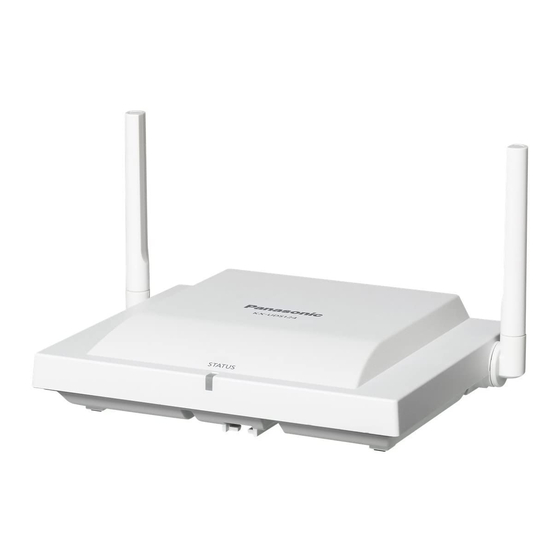
3 Installing the SIP Cell Stations 3 Installing the SIP Cell Stations 3.1 Overview of SIP Cell Stations Names and Locations Antennas RJ45 Modular CS ID Number RESET Switch (ID: xxxxxxxxxx) DC Jack MAC Address Unpacking Unpack the box and check the items below: SIP Cell Station Screws Washers... -
Page 17: Led Indications
3 Installing the SIP Cell Stations LED Indications SIP-CS State Description General Operation • OFF: Power Off/SIP-CS Software downloading • Green ON: Stand-by (no active calls) • Slow green flashing: Talk (active calls) / S-PS data transfer • Moderate green flashing: Busy •... -
Page 18: Connecting Sip Cell Stations
3 Installing the SIP Cell Stations 3.2 Connecting SIP Cell Stations Connecting a SIP-CS to a LAN Notice • Connect the SIP-CSs to the LAN only after completing network settings. For details about network settings, see "Configuring Network Settings for Air Sync Master CS" in "4.3 Site Survey". •... - Page 19 3 Installing the SIP Cell Stations Connecting an AC Adaptor to a SIP-CS SIP-CSs comply with the IEEE 802.3af Power-over-Ethernet (PoE) standard. If PoE is available on your network, these SIP-CSs can receive the necessary power supply from the network through the network cable. In this case, no AC adaptor is needed for the SIP-CSs.
-
Page 20: Wall Mounting
Make sure the cables are securely fastened to the wall. Notice Panasonic assumes no responsibility for injuries or property damage resulting from failures arising out of improper installation or operation inconsistent with this documentation. Place the reference for wall mounting on the wall to mark the 2 screw positions. - Page 21 3 Installing the SIP Cell Stations Position the antennas according to the following illustration so that they are pointing in directions that are 90 degrees apart (for antenna diversity). 45º 90º 45º Reference for Wall Mounting Please copy this page and use as a reference for wall mounting. Install a screw here.
-
Page 22: Deployment Procedure
4 Deployment Procedure 4 Deployment Procedure The deployment procedure for establishing a wireless system is as follows. Note The deployment procedures of "5. Configuration" and "6. S-PS Registration" in "4.1 Overview" differ from each other depending on the SIP server (KX-NS1000 or third party SIP server) used in the system. Conditions for Configuring the Air Synchronisation Notice For General Networking... -
Page 23: Tree Survey
Station Unit" on the following web Tool Programming same network. site for more information: This method provides a more accurate http://panasonic.net/pcc/support/ Tree Survey. sipphone Notice If the Tree Survey is going to be conducted for 10 or more SIP-CSs, use the CS Maintenance Tool. - Page 24 4 Deployment Procedure 7. S-PSs Area Check Check the service area, sound quality, and handover operation under actual conditions. Installation Guide...
-
Page 25: Site Planning
4 Deployment Procedure 4.2 Site Planning In order to be able to move between coverage areas during a call (Handover), synchronisation between SIP-CSs is necessary. If synchronisation between SIP-CSs has not been configured, handover will fail. The source of synchronisation is called a Master CS and the target of synchronisation is called a Slave CS. An Air Sync Group is created with the Master/Slave CSs on different levels. - Page 26 4 Deployment Procedure Good Example: The Master CS is located in the centre of the installation site for each Air Sync Group. Number of Master/Slave level: 5 Bad Example: The Master CS is NOT located in the centre of the installation site for each Air Sync Group. Therefore, the number of layers in the hierarchy exceeds 8.
- Page 27 4 Deployment Procedure Radio waves are reflected by objects made of materials such as metal. Radio waves are diffracted by objects such as metallic columns. Radio waves penetrate objects made of materials such as glass. 1. Reflection SIP-CS Column 2. Diffraction 3.
- Page 28 4 Deployment Procedure Object Material Transmission Tendency Column Ferroconcrete Radio waves can penetrate them, but the more iron there is, the more radio waves tend to be reflected or diffracted. Metal Radio waves tend to be reflected or diffracted. Cabinet Steel Radio waves are usually reflected or diffracted, and rarely penetrate them.
- Page 29 4 Deployment Procedure Example 1 30 m 30 m Example 2 10 m 10 m 10 m Example 3 10 m 10 m 10 m 10 m Notice • It may not be possible to create an Air Sync Group that spans multiple floors, because the dividing ceilings may weaken the signal too much.
-
Page 30: Air Synchronisation
4 Deployment Procedure • When creating an Air Sync Group that spans multiple floors, make sure that you conduct a site survey across the floors. • Make the SIP-CS that is adjacent to most other SIP-CSs (in all 3 dimensions) into the Master CS. Air Synchronisation Air synchronisation assigns classifications to SIP-CS and establishes connections based on those classifications. -
Page 31: Site Survey
Battery cable: PSJS02P57 One of either Source PoE Hub IEEE802.3af certified PoE Adaptor IEEE802.3af certified SIP-CS KX-UDS124 S-PS KX-UDT111, KX-UDT121, KX-UDT131 Site map Map of site or floor. Pencil To write the MAC addresses and radio signal values on the site map. - Page 32 4 Deployment Procedure Confirming SIP-CS Coverage Area for Air Synchronisation between SIP-CSs Confirm the radio signal strength of the SIP-CS at each planned location. The SIP-CS’s LED indicates the strength of the wireless connection. LED: Site Survey : Planned Location Red and green alternate flashing Master Mode Power...
- Page 33 4 Deployment Procedure Area Description Air synchronisation coverage area (Radius: About 1 m to 40 m) S-PS coverage area (Radius: About 1 m to 50 m) Site Survey for Air Synchronisation After completing site planning, you can use 2 SIP-CSs to conduct the site survey to check radio signal strength. Then, if necessary, modify the location of the SIP-CSs accordingly.
- Page 34 4 Deployment Procedure Place SIP-CS(1) where the Air Sync Master CS is planned to be located. LED: Red and green alternate flashing SIP-CS(1) Power (Site Survey Planned Location: Source Master Mode) Planned Location for Air Sync Master CS Place SIP-CS(2) in the location planned for the SIP-CS closest to the Air Sync Master CS (currently SIP-CS[1]).
- Page 35 4 Deployment Procedure Note • For air synchronisation radio signal strength details, refer to "LED Indications for Site Survey Mode" table found in "4.3 Site Survey". Power Source SIP-CS(1) LED: Slow amber flashing Power Source SIP-CS(2) Power Source SIP-CS(1) LED: Slow green flashing Power Source...
- Page 36 4 Deployment Procedure Confirm whether the LED of SIP-CS(2) is green. If it is not green, move SIP-CS(2) around to find a location where its LED turns green. LED: Slow amber flashing Power SIP-CS(1) Source Power SIP-CS(2) Source LED: Slow green flashing SIP-CS(1) Power Source...
- Page 37 4 Deployment Procedure Site Survey for S-PS Service Area Each S-PS has a CS Area Check mode that monitors the state of the radio link to the SIP-CS to check the S-PS service area for establishing conversations. In CS Area Check mode, the following are displayed on the S-PS with a refresh interval of 2 seconds: the SIP-CS ID of the SIP-CS to which the S-PS is connected, the radio strength level, and the Error Rate.
- Page 38 4 Deployment Procedure The Maintenance mode main menu will be displayed. Site Survey for S-PS Service Area Place a SIP-CS in the location confirmed for the Air Sync Master CS in the previous site survey. Supply power to the SIP-CS. Perform the next step according to the registration state of the S-PS, as follows: •...
- Page 39 4 Deployment Procedure In the coverage area, the RSSI level should be more than 8 and the error rate should be less than 2 %. Example: Power Source Power Source Exiting Site Survey Master Mode While the SIP-CS is in Site Survey Master Mode, press the RESET switch to exit. Installation Guide...
-
Page 40: Example Of How To Conduct The Site Survey
4 Deployment Procedure 4.4 Example of How to Conduct the Site Survey Set the S-PS to CS Area Check mode and walk around the site survey Master CS to confirm the CS coverage area. The recommended area is where the RSSI is more than 8 and the Error Rate is less than 02%. -
Page 41: Example Of How To Make A Site Map
4 Deployment Procedure 4.5 Example of How to Make a Site Map Write down the MAC address of each CS on the map. (The MAC address is written on the rear side of each CS.) In case of network trouble, you can confirm which CS is not connected using the map. Example of Site MAP (1) (CS MAC addresses) PoE Hub... -
Page 42: Basic Network Configuration
4 Deployment Procedure 4.6 Basic Network Configuration Configuring Network Settings for Air Sync Master CS Setting Up with a Fixed IP Address Turn on the SIP-CS while holding the RESET switch. After the LED flashes red, amber and green alternately, release the RESET switch. Note The IP address and subnet mask are as follows: •... - Page 43 4 Deployment Procedure Assigning IP Address Information The Super Master CS must have a static IP address. Follow the procedure below to configure static IP address information. (The following procedure can be omitted for Air Sync Groups 2–8.) In the Network tab, select Basic Network Settings. In Connection Mode, select Static.
- Page 44 4 Deployment Procedure Configuring Air Synchronisation Settings Follow the procedure below to change the SIP-CS status to Master. In the System tab, select Air Settings. Select an Air Sync Group. (Group 1 must be selected for the Super Master CS.) In CS Class, select Master.
-
Page 45: Password Security
4 Deployment Procedure Log out from the Web User Interface, and then log in again. The new password will be saved and the SIP-CS will restart. Note The new password will be applied to all registered SIP-CSs automatically. Password Security CAUTION •... -
Page 46: Cs Registration
4 Deployment Procedure 4.7 CS Registration : Ethernet Cable Master CS : Air Synchronisation (Site Survey Mode) PoE Hub Notice • Connect each SIP-CS in the Air Sync Group to the network and turn them on. • During CS Registration, make sure that all unregistered SIP-CSs that are not in the Air Sync Group you are registering are turned off. - Page 47 4 Deployment Procedure Registering SIP-CSs to the Air Sync Master CS (Air Sync Group 1) In the System tab, select CS Management. Select the number of SIP-CSs to register newly from the Number of CS pull-down menu. Click Start CS Registration. Click OK.
- Page 48 4 Deployment Procedure • After clicking Start CS Registration, when the number of registered SIP-CSs reaches the number specified in Number of CS, "Complete" is displayed and registration stops automatically. • Click Stop CS Registration to quit registration. • If you want to register all SIP-CSs in step 3, select the maximum number of SIP-CSs. In this case, after the detected SIP-CSs have been registered, wait 5 minutes for the timeout display or click Stop CS Registration.
-
Page 49: Tree Survey
4 Deployment Procedure 4.8 Tree Survey The Tree Survey creates the most suitable synchronisation tree automatically for SIP-CSs. You also can configure Air Sync Groups in this procedure. The Tree Survey creates a Master/Slave tree structure with the Air Sync Master CS at the top and with stable air synchronisation. - Page 50 4 Deployment Procedure Click Start Tree Survey. Click OK. After the Tree Survey has completed, results will be displayed. Click OK. Note Click Tree Image to see a connection diagram of the SIP-CSs Notice If the Tree Survey will be conducted for 10 or more SIP-CSs, use the CS Maintenance Tool instead. For details, see "4.
-
Page 51: Configuration And Ps Registration (For A System Using A Kx-Ns1000)
4 Deployment Procedure 4.9 Configuration and PS Registration (for a system using a KX-NS1000) 4.9.1 Programming using Web Maintenance Console The following items must be programmed using the KX-NS1000's Web Maintenance Console. • V-UTEXT32 card (Virtual UT Extension Card) • Extension settings for S-PSs •... - Page 52 4 Deployment Procedure Adding a V-UTEXT32 Card to the KX-NS1000 Click Setup ® PBX Configuration ® Configuration ® Slot ® Virtual. Click on the V-UTEXT32 tab. Select the number of cards to install of that type from the Total number of cards drop-down list. The selected number of cards will fill free virtual slots.
- Page 53 4 Deployment Procedure Assigning an extension number to an S-PS Click Setup ® PBX Configuration ® Configuration ® Slot ® Virtual. Click on the V-UTEXT32 tab. Move the mouse pointer over the V-UTEXT32 card (Virtual UT Extension Card). A menu will be shown under the mouse pointer. Click Port Property.
- Page 54 4 Deployment Procedure Programming Flexible buttons Click Setup ® PBX Configuration ® Extension ® Wired Extension ® Flexible Button. Programme the flexible buttons. Note You can programme the following flexible buttons to S-PSs. For details about each flexible button, refer to the Feature Guide of the KX-NS1000.
- Page 55 4 Deployment Procedure Programming an Extension Number for the Super Master CS Click Setup ® PBX Configuration ® Configuration ® Slot. Click Virtual ® V-UTEXT32. Move the mouse pointer over the V-UTEXT32 card (Virtual UT Extension Card). A menu will be shown under the mouse pointer. Click Port Property.
-
Page 56: Programming Using The Web User Interface
4 Deployment Procedure Specifying a Terminal Type for S-PSs, SIP-CSs and the Super Master CS Click Setup ® PBX Configuration ® Configuration ® Slot. Click Virtual ® V-UTEXT32. Move the mouse pointer over the V-UTEXT32 card (Virtual UT Extension Card). A menu will be shown under the mouse pointer. -
Page 57: Registering S-Pss To The Super Master Cs
4 Deployment Procedure Specifying the URL to Access the KX-NS1000 Login to the Web user interface as the administrator. Click Maintenance ® Provisioning Maintenance. Enter the IP address and port number of the KX-NS1000 as shown below in System File URL. http://xxx.xxx.xxx.xxx:yyyy/utdownload/System.cfg Note •... -
Page 58: Programming Ps Ring Group
4 Deployment Procedure 4.9.4 Programming PS Ring Group Overview of the PS Ring Group feature with SIP-CSs SIP-CSs can provide the PS ring group feature. To use the feature, you must set the PS Ring Group setting of the SIP-CS and the ICD group setting of the KX-NS1000. A PS Ring Group of the SIP-CS is a group of S-PS extensions that receive the same incoming calls. - Page 59 4 Deployment Procedure Note The floating extension number assigned to the ICD groups (e.g., 600) is used for calling multiple S-PSs simultaneously. SIP-CS SIP-CS PS Ring Group 600 PS Ring Group 600 Ext.300 Ext.301 SIP-CS PS Ring Group 600 Ext.302 Installation Guide...
- Page 60 4 Deployment Procedure The following illustration is an example of an incoming call received by S-PSs with the ICD group setting and PS Ring Group setting enabled. ncoming call (To Ext. 600) ICD Group 2 ICD Group 1 Floating extension no.: 601 Floating extension no.: 600 Members: Members:...
- Page 61 4 Deployment Procedure Notice If an extension number of an S-PS is set directly to the ICD Group, the SIP-CS receives the incoming call as a group call. Therefore, the number of ICD Group members will be restricted since the maximum number of simultaneous calls per SIP-CS is 4.
- Page 62 4 Deployment Procedure SIP-CS match the one already input in the KX-NS1000's Web Maintenance Console, the SIP-CS will be registered automatically. Programming a PS Ring Group with the Web User Interface of SIP-CSs Assigning extension number to SIP-CSs Assign the preconfigured extension number to each SIP-CS that will be a member of the ICD group. Logging in to a SIP-CS You can log in to each SIP-CS via the Web user interface of the Super Master CS.
- Page 63 4 Deployment Procedure Click Login for the corresponding SIP-CS, in CS Registered List. Assigning an extension number to a SIP-CS Follow the procedure below to assign the extension number to the SIP-CS you are logged in to. In the VoIP tab, select SIP Settings - CS. Enter the SIP-CS's extension number in Phone Number.
- Page 64 4 Deployment Procedure In the Telephone tab, click PS Ring Group Settings. Click PS Group xx Registration for the group you want to programme. Select the S-PSs to be registered in Available Users, and then click To select all available S-PSs, click .
-
Page 65: Configuration And Ps Registration (For A System Using A Third Party Sip Server)
4 Deployment Procedure 4.10 Configuration and PS Registration (for a system using a third party SIP server) 4.10.1 Programming SIP-CSs for a Third Party SIP Server Specifying the SIP Server’s Information Follow the procedure below to specify the IP address and port number of the SIP server to which the Super Master CS is connected. -
Page 66: Ps Registration
4 Deployment Procedure Specifying the Preferred Codec Follow the procedure below to specify the codecs you want to use and their usage priorities. In the VoIP tab, select VoIP Settings. In CODEC Preferences, select a codec to use and specify its priority. Click All Save. - Page 67 4 Deployment Procedure Registering Extension Numbers and Extension Names for S-PSs Follow the procedure below to assign extension numbers and extension names to the S-PSs. In the System tab, select PS Registration. Enter an extension name in PS Name. Click All Save. Select Line 1 SIP Setting or Line 2 SIP Setting.
- Page 68 4 Deployment Procedure Enter the Phone Number, and enter Authentication ID and Authentication Password if necessary. Click All Save. Click Back. Repeat steps 2 to 7 for each S-PS. Note If the S-PS name is too long to display, the end of the name may not be displayed on the S-PS’s standby screen.
- Page 69 4 Deployment Procedure Hold down until "Please wait…" is displayed. When registration has completed, "Registered" will be displayed. Note • You can register multiple S-PSs continuously. However, PS Registration mode will terminate if no registrations are detected within 2 minutes (If the IPEI is registered by provisioning, there is no time limit.).
- Page 70 4 Deployment Procedure Checking Progress You can check registration progress on the PS Registration screen. If Trying is displayed on the left of the screen, you can check the registration status of each S-PS in the Wireless Status field. If PS Registration Complete is displayed on the left of the screen, all S-PSs that selected for registration were registered successfully.
- Page 71 4 Deployment Procedure In the System tab, select PS Registration ® Delete PS Registration. Select the S-PSs to be unregistered in Available PS, and then click To select all available S-PSs, click . To deselect S-PS(s), click Click Next. Click OK to confirm unregistration. Unregistering a Base System from the S-PS If the S-PS was outside the coverage area or was turned off when the above-mentioned unregistration procedure was performed, you must unregister the base system manually.
-
Page 72: How To Back Up And Restore Configuration Data
4 Deployment Procedure 4.11 How to back up and restore configuration data It is recommended to keep a backup of Super Master CS configuration data. The backup data is useful when restoring the same configuration data to the Super Master CS when it must be re-installed due to a hardware error, etc. -
Page 73: Ps Area Check
4 Deployment Procedure 4.12 PS Area Check In this section, you can check the service area, handover and voice quality using 2 registered S-PSs under actual conditions. Entering S-PS Area Check mode Start the S-PS in Maintenance mode. For details, see "Starting the S-PS in Maintenance Mode" in "4.3 Site Survey". Select "PS area check", and then press Select "On". - Page 74 4 Deployment Procedure • SIP-CSs with a signal strength that is sufficiently strong but that are not currently connected are also displayed in green on the S-PS's LCD screen. • When the S-PS moves towards another SIP-CS, the RSSI level of the currently connected SIP-CS changes.
-
Page 75: Troubleshooting
5 Troubleshooting 5 Troubleshooting This section provides information on SIP-CS and S-PS troubleshooting. When the KX-NS1000 is also used with SIP-CSs and S-PSs, refer to this section and troubleshooting section of the KX-NS1000's Installation Manual. CS Registration Notices When you cannot register any SIP-CSs, the cause may be one of the following: In the case of Air Sync Group 1 •... - Page 76 5 Troubleshooting Message Probable Cause Solution ERROR!!! CS does not A SIP-CS has radio signal trouble. Please check whether a radio signal have Primary CS. obstacle, such as a metal shelf, a door, etc., exists near the SIP-CS. ERROR!!! Unknown error Tree Survey failed for some reason.
-
Page 77: Appendix
6 Appendix 6 Appendix 6.1 Specifications SIP-CS Specification Type 4 channel CS with wideband audio Supported Audio Wideband Narrowband Radio Method DECT VoIP Signalling Protocol IP Port Number Flexible Setting Local Setting Yes (through Web application) Site Survey Mode Initialisation Maximum Simultaneous Calls Power Supply (IEEE 802.3af Class1) - Page 78 6 Appendix Items KX-UDT111 KX-UDT121 KX-UDT131 1.8 inch colour Bluetooth Vibration Battery Ni-MH Li-Ion Number of Simultaneous Registered Systems Software Upgrade Yes (Wireless Download) RF Specification Item Description Radio Access Method MultiCarrier TDMA-TDD Frequency Band 1880 MHz to 1900 MHz Number of Carriers Carrier Spacing 1728 kHz...
- Page 79 6 Appendix Model No. Part No. Type KX-A239CE PQLV206CE KX-A239BX KX-A239UK PQLV206E KX-A239EJ KX-A239AL PQLV206AL Installation Guide...
- Page 80 Web Site: http://www.panasonic.net/ Copyright: This material is copyrighted by Panasonic System Networks Co., Ltd., and may be reproduced for internal use only. All other reproduction, in whole or in part, is prohibited without the written consent of Panasonic System Networks Co., Ltd.