Bosch D6600 Operation And Installation Manual
Receiver/gateway
Hide thumbs
Also See for D6600:
- Manual (185 pages) ,
- Installation and operation manual (88 pages) ,
- Installation manual (4 pages)
Table of Contents
Advertisement
Quick Links
Advertisement
Table of Contents

Related Manuals for Bosch D6600


Summary of Contents for Bosch D6600
- Page 1 D6600 Operation and Installation Guide Receiver/Gateway...
- Page 2 D6600 | Operation and Installation Guide | Trademarks Trademarks ® ® ® Microsoft , Windows , Windows NT are either registered trademarks or trademarks of Microsoft Corporation in the United States and/or other countries. Bosch Security Systems | 2/05 | 4998122704E...
-
Page 3: Table Of Contents
D6600 | Operation and Installation Guide | Contents Contents Introduction ..........5 10.1.5 Message is Received ........18 Documentation Conventions ......6 10.1.6 How Call Groups Work ........18 10.1.7 Buzzer Operation ..........18 Emergency Procedures ........6 Card Functions and Locations....... 7 10.1.8 Reporting Devices: Primary and... - Page 4 D6600 | Operation and Installation Guide | Contents Figures Tables Figure 1: D6600 Communications Table 1: D6600 Supported Communication Receiver/Gateway (front view) ....7 Formats ............5 Figure 2: D6600 Communications Table 2: Battery Supervision........7 Receiver/Gateway (rear view) ....8 Table 3: System Trouble ...........
-
Page 5: Introduction
Up to seven additional telephone line cards along with zone, and point. The printer tape and the D6600 LCD seven additional line terminator cards can be installed display show other receiver status messages such as in the D6600 to expand the receiver’s capacity to 32... -
Page 6: Documentation Conventions
D6600 | Operation and Installation Guide | 2.0 Emergency Procedures Documentation Conventions 2.0 Emergency Procedures Section 17.0 Service Information on page 32 of this guide Important Notes - Information for contains a Service Information form. Keep this form successful operation and programming. -
Page 7: Card Functions And Locations
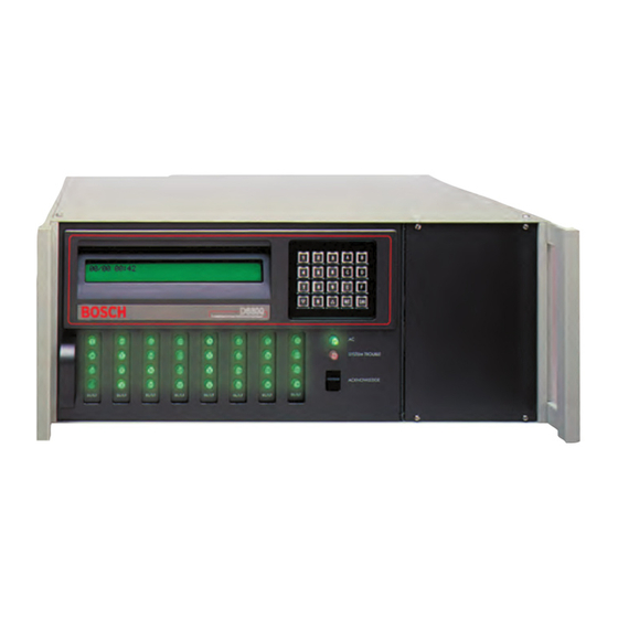
D6600 | Operation and Installation Guide | 3.0 Card Functions and Locations 3.0 Card Functions and Table 3: System Trouble Locations System Trouble LED Status Front Panel Solid Red Clear No System Trouble Figure 1: D6600 Communications Receiver/Gateway (front view) -
Page 8: Rear View
D6600 | Operation and Installation Guide | 3.0 Card Functions and Locations Rear View The D6600 has input and output pin connector sockets for up to eight line cards, network option (if installed), and one CPU card. It also has slots for connecting these cards to their corresponding terminator cards. -
Page 9: D6600 Specific Cards
D6600 | Operation and Installation Guide | 4.0 D6600 Specific Cards Figure 5: D6645 Line Terminator Card 4.0 D6600 Specific Cards D6640/D6641 Line Cards and D6645 Line Terminator Card Figure 4: D6640/D6641 Line Card 1 - 48-pin connection to D6640/D6641 Line Card... -
Page 10: Card Installation
D6600 | Operation and Installation Guide | 4.0 D6600 Specific Cards 4.1.2 Card Installation Figure 8: Inserting the D6645 Line Terminator Card Power down the receiver when removing, replacing, or installing telephone line cards or telephone line terminator cards (refer to Section 7.7 Powering Down the Receiver on page 13). -
Page 11: Telephone Line Monitoring Voltage
D6600 | Operation and Installation Guide | 4.0 D6600 Specific Cards 7. Mount the terminator card (Item 1, Figure 9 on page D6610 CPU Card and D6615 CPU 10) in an empty slot (Item 3, Figure 9) of the Terminator Card receiver cabinet (Item 4, Figure 9) by securing the 4.2.1... -
Page 12: Card Removal And Replacement
D6600 | Operation and Installation Guide | 5.0 Power Supply Modules 4.2.3 Card Removal and Replacement 7.0 Installation Power down the D6600 before removing, All Installations replacing, or installing the CPU card Install the D6600 Communications Receiver/Gateway (D6610) or CPU terminator card according to the National Electrical Code (NEC), (D6615). -
Page 13: Fire Alarm Applications
(per NFPA 72, 1-5.2.5.2) to meet the mechanical protection requirement when using the Installation Check List type of AC cord provided with the D6600. It is also 1. Check each receiver card to see that they are required that a UL Listed rack for fire protective... -
Page 14: Connecting External Batteries
D6600 | Operation and Installation Guide | 8.0 Standby Power Connecting External Batteries Table 5: Battery Voltage Display Do not connect an external battery charger to the D6600. Battery Voltage Display (during Display (if AC power battery missing outage) when AC power... -
Page 15: Input And Output Ports
D6600 | Operation and Installation Guide | 9.0 Input and Output Ports 9.0 Input and Output Ports Because the input state is undefined in the voltage range, input voltages between 1 V and 3 V can cause abnormal results. Figure 12: D6600 Back Panel Showing... -
Page 16: Automation Link Monitoring (Com3)
D6600 | Operation and Installation Guide | 10.0 D6600 Operation D6600 Automation Link Monitoring (COM3) through CPU Programmable Output Ports The output connections on the I/O port have an open collector transistor output that can activate an external Enter password. -
Page 17: Receiver Handshake And Kiss-Off
10.1.2 Receiver Handshake and Kiss-Off The telephone line dialed by the communicator connects to a line card in the D6600. The line card detects ringing voltage, answers the incoming call, and sends a programmed series of handshake tones. The communicator detects the expected handshake and transmits its message. -
Page 18: Message Verification
D6600 | Operation and Installation Guide | 10.0 D6600 Operation Program the receiver for up to eight handshake Many control panels can transmit multiple messages in attempts, using any combination of the available the same telephone call. Program the receiver to print handshake tones. -
Page 19: Normal Operation Mode
(such as printers and If all reporting devices (such as printers and computers) computers) fail, the receiver re-routes the messages to fail, the D6600 reverts to Manual Mode until a device the secondary reporting device(s). If the receiver returns to service. -
Page 20: Using The Keypad
D6600 | Operation and Installation Guide | 10.0 D6600 Operation D6600 D6600 D6600 D6100 10.4.2 Using the Keypad MENU D6600 Scrolls up or down to the appropriate menu. D6600 D6600 D6600 Browse the system troubles in Enters a particular menu. -
Page 21: Skip Current Automation Event
D6600 | Operation and Installation Guide | 10.0 D6600 Operation D6600 D6600 default password: 6600 D6600 D6600 Table 9: Testing Communication Links DD/DDsTT:TTsL08sACCTs888sss[TES Printer T]sZNsss8 D6600 D6500 h1rr8sssssss888s[sss8t Automation Mode <header>[NVX] SIA Mode 10.4.7 Skip Current Automation Event D6600 Use this option to skip the current Automation event. -
Page 22: Busy Seconds (Line Busy) Reports
Cancels the function and does the central station Private Branch Exchange (PBX) not delete all pending events. system, taking the D6600 off line in a short period. If a PBX is not used, connect a regular telephone in D6600 Clears all pending events. -
Page 23: Enhancements And Changes
When pressing [CAN] during the two-way audio session, the receiver prompts the operator to enter the line number for stopping the two-way audio. Ensure the D6600 is not in Menu Mode during this operation. The OL/LF LED flashes green during the audio session. -
Page 24: Network Communications
D6600 | Operation and Installation Guide | 11.0 Network Communications 11.0 Network Communications Figure 14: D6600 NetCom System Connection Diagram - C900TTL-E and Any Control The D6600 Central Station Communications Panel Receiver/Gateway NetCom system supports data network communications. NetCom allows the D6600... -
Page 25: No Data Received Reports
Data Error is a function of PSTN. It is an error Administrative Software condition when the D6600 receives partial data, Ethernet hub appears on the D6600 LCD, and sends the error to a D6680 Network Adapter connected printer. D6600 Receiver This occurs when telephone line noise causes data to Connection –... -
Page 26: Using The Central Station Automation System With The D6600
D6600 | Operation and Installation Guide | 13.0 Using the Central Station Automation System with the D6600 13.0 Using the Central Station Figure 18: D6600 System – Standard/Network Automation Automation System with the D6600 If using a D6600, connect a central station automation... -
Page 27: Central Station Tips
D6600 | Operation and Installation Guide | 14.0 Central Station Tips 14.5 Proper Ground 14.0 Central Station Tips Connect the receivers to an earth ground, not a 14.1 Back-up Receiver chassis or electrical ground. Measure the resistance of Spare circuit boards and receivers should be available the receiver ground to another ground. -
Page 28: Troubleshooting Guide
D6600 | Operation and Installation Guide | 15.0 Troubleshooting Guide 15.0 Troubleshooting Guide The D6600 consists of several plug-in assemblies that you can easily replace in the field (components and controls on individual assemblies are shown starting in Section 3.0 Card Functions and Locations on page 7). - Page 29 Check watchdog LED on the inside of the door behind the buzzer cannot be keypad. LED must flash for a running system. A solid light does silenced. not indicate a running system. Reset power cycle of the D6600 if stalled. • •...
- Page 30 PC running the D6200 software must be entered into the D6600 through a incorrect network cable. D6600 Menu Items 6.4.1 IP Address 1, 6.4.2 IP Address 2, or network connection. 6.4.3 IP Address 3. • If communicating over a WAN, the external IP address of the LAN with the PC running the D6200 software must be entered into the D6600’s Menu Items 6.4.1 IP Address 1, 6.4.2 IP...
-
Page 31: Specifications
10 mA Standby Power Use a UPS with the D6600. The receiver includes an external battery connection and battery harness. Use 12 V rechargeable sealed lead-acid batteries. A 4-hour minimum standby power supply (UPS or battery) is required for UL Certification (refer to Section 8.1 Connecting External Batteries on page 14 for battery size). -
Page 32: Service Information
17.0 Service Information (EMERGENCY DATA SHEET) In a central station emergency, use this information to contact the necessary people and enable Bosch Security Systems Customer Service Personnel to help you with your emergency. Have your supervisor provide you with the following information: Supervisor’s Name:... - Page 33 D6600 | Operation and Installation Guide | Notes17.0 Service Information Notes Bosch Security Systems | 2/05 | 4998122704E...
- Page 34 D6600 | Operation and Installation Guide | Notes Notes Bosch Security Systems | 2/05 | 4998122704E...
- Page 35 D6600 | Operation and Installation Guide | Notes17.0 Service Information Notes Bosch Security Systems | 2/05 | 4998122704E...
- Page 36 Bosch Security Systems 130 Perinton Parkway Fairport, NY 14450-9199 Customer Service: (800) 289-0096 Technical Support: (888) 886-6189 © 2005 Bosch Security Systems 4998122704E...