
Related Manuals for Hitachi S 15SA


Summary of Contents for Hitachi S 15SA
- Page 1 MODELS S 15SA S 18SA POWER TOOLS TECHNICAL DATA DISC SANDERS S 15SA, S 18SA SERVICE MANUAL LIST Nos. S 15SA: 0349 Sep. 1999 S 18SA: 0350 SPECIFICATIONS AND PARTS ARE SUBJECT TO CHANGE FOR IMPROVEMENT...
- Page 2 REMARK: Throughout this TECHNICAL DATA AND SERVICE MANUAL, a symbol(s) is(are) used in the place of company name(s) and model name(s) of our competitor(s). The symbol(s) utilized here is(are) as follows: S 15SA Competitor Symbol Utilized Company Name Model Name...
-
Page 3: Table Of Contents
[ Appendix ] Assembly Diagram for S 15SA • • • • • • • • • • • • • • • • • • • • • • • • • • • • • • • • • • • • • • • • • • • • • • • • • • • • • • • • • • • • • • • • • • • • • • • • • • • • • • • • • • • • • • • • • • • • • • • • • • • • • • •... -
Page 4: Product Name
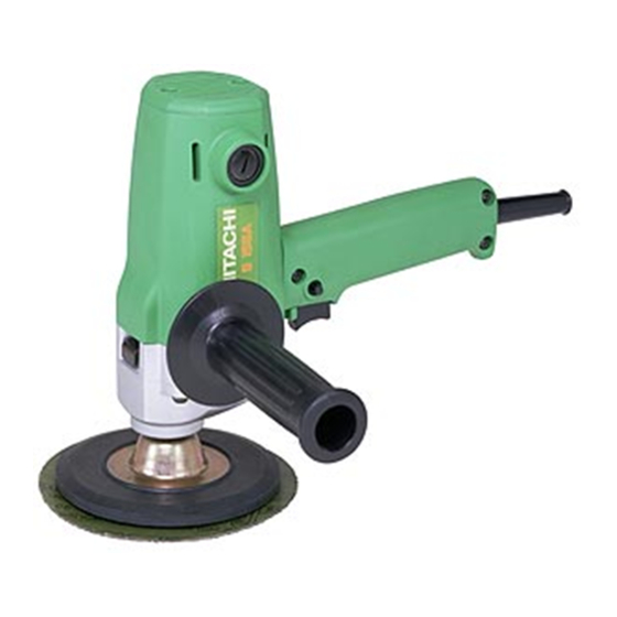
S 18SA [180 mm (7")] 2. MARKETING OBJECTIVE The Models S 15SA and S 18SA are high-power and double-insulated disc sanders with a stand-up design specially developed to meet customer demands in European and Asian markets. These disc sanders will make it possible to exploit new markets because they are the first products in our disc sander line to satisfy this range of demands. -
Page 5: Selling Point Descriptions
(Maximum output may vary depending on market area.) 2) Convenient spindle lock The Models S 15SA and S 18SA are the first disc sanders in the disc sander industry equipped with a convenient spindle-lock mechanism. Thanks to this mechanism, tools can be easily replaced as shown in Fig. 1. - Page 6 3) Excellent overload durability The Models S 15SA and S 18SA provide excellent overload durability thanks to the improved cooling fan and cooling air passage design as well as the high-power motor. Overload durability is defined as the amount of thrust force required to raise the stator coil temperature by 200 K, and the ratio of these models to similar products C-1 and C-2 is indicated in Table 2.
-
Page 7: Specifications
5. SPECIFICATIONS Model S 15SA S 18SA Item 150 mm (6") 180 mm (7") Capacity Power source AC single phase 50 or 60 Hz Voltage (V) Current (A) Power input (W) Voltage, current and power input 4,000 /min Rotation speed (no-load) -
Page 8: Comparisons With Similar Products
6. COMPARISONS WITH SIMILAR PRODUCTS 6-1. Specification Comparisons Maker HITACHI C-1 / C-2 Model S 15SA / S 18SA Capacity 150 (6") / 180 (7") 150 (6") / 180 (7") Power input Power output 390 (0.5 hp) 340 (0.5 hp) Max. -
Page 9: Practical Test Data
The graph below shows the relationship between the rotation speed and the stator coil temperature rise while varying loads. The temperature rise of the Model S 18SA (the Model S 15SA is similar) is lower than that of the similar product C-2. -
Page 10: Precautions In Sales Promotion
7. PRECAUTIONS IN SALES PROMOTION In the interest of promoting the safest and most efficient use of the Models S 15SA and S 18SA Disc Sanders by all of our customers, it is very important that at the time of sale, the salesperson carefully ensures that the buyer seriously recognizes the importance of the contents of the Handling Instructions, and fully understands the meaning of the precautions listed on the Name Plate attached to each tool. -
Page 11: Precautions In Disassembly And Reassembly
The [Bold] numbers in the descriptions below correspond to the item numbers in the Parts List and exploded assembly diagram for S 15SA and the <Bold> numbers to those in the Parts List and exploded assembly diagram for S 18SA. -
Page 12: Disassembly Of The Stator Ass'y
8-2. Disassembly of the Stator Ass'y (1) After taking off the Armature Ass'y [13] <13>, loosen the five Tapping Screws D4 X 20 [26] <26> and remove the Tail Cover [25] <25>, the Handle Cover [29] <29> and the Fan Guide [16] <16>. (2) Disconnect the lead wires of the Stator Ass'y [17] <17>... -
Page 13: Reassembly
8-4. Reassembly Reform reassembly in the reverse order of disassembly while ovserving the given precautions and taking care of the following points. (1) After disassembly, thoroughly remove old grease from the inside of the Gear Cover [8] <8>, and insert 15 g of new grease (Nippeco JF-375, Code No. -
Page 14: Insulation Tests
8-7. Insulation Tests On completion of reassembly after repair, measure the insulation resistance and conduct the dielectric strength test. 7 M Ω or more with DC 500V Megohm Tester Insulation resistance: Dielectric strength: AC 4,000 V for 1 minute, with no abnormalities 220 V --- 230 V •... -
Page 15: Standard Repair Time (Unit) Schedules
9. STANDARD REPAIR TIME (UNIT) SCHEDULES Variable MODEL 60 min. Fixed Work Flow G 15SA G 18SA Switch Cord Housing Ass'y Stator General Assembly Armature Ass'y Ball Bearing (6000DD) Ball Bearing (608VV) Dust Seal Inner Cover Gear Cover First Gear Ball Bearing (6201DD) Spindle... -
Page 16: Assembly Diagram For S 15Sa
Assembly Diagram for S 15SA --- 13 ---... - Page 17 S 15SA PARTS ITEM CODE NO. DESCRIPTION REMARKS USED 953-381 WASHER NUT 935-652 RUBBER PAD 944-005 BEARING CAP 317-895 SPINDLE 620-1DD BALL BEARING 6201DDCMPS2L 939-542 RETAINING RING FOR D12 SHAFT (10 PCS.) 316-321 TAPPING SCREW (W/FLANGE) D5X45 318-017 GEAR COVER...
- Page 18 S 15SA STANDARD ACCESSORIES ITEM CODE NO. DESCRIPTION REMARKS USED 937-913Z WRENCH OPTIONAL ACCESSORIES ITEM CODE NO. DESCRIPTION REMARKS USED 314-073 SANDING DISCS 150MM C-P16 (10 PCS.) 314-074 SANDING DISCS 150MM C-P20 (10 PCS.) 314-075 SANDING DISCS 150MM C-P24 (10 PCS.) 314-076 SANDING DISCS 150MM C-P30 (10 PCS.)
-
Page 19: Assembly Diagram For S 18Sa
Assembly Diagram for S 18SA --- 16 ---... - Page 20 NOISE SUPPRESSOR FOR ITA,FRG,FRA,ESP,CHN 311-741 TERMINAL FOR NOISE SUPPRESSOR 959-144 TERMINAL 50051 (10 PCS.) FOR NOISE SUPPRESSOR 302-477 SWITCH (C) (1P SCREW TYPE) W/LOCK HITACHI LABEL 317-893 DUST PACKING 980-063 TERMINAL FOR CORD 984-750 TAPPING SCREW (W/FLANGE) D4X16 960-266 CORD CLIP 953-327 CORD ARMOR D8.8...
- Page 21 S 18SA PARTS ITEM CODE NO. DESCRIPTION REMARKS USED 500-240Z CORD (CORD ARMOR D8.8) FOR USA 5 ---- 99 : ALTERNATIVE PARTS --- 18 ---...
-
Page 22: Optional Accessories
S 18SA STANDARD ACCESSORIES ITEM CODE NO. DESCRIPTION REMARKS USED 937-913Z WRENCH 314-090 SANDING DISCS 180MM C-P50 (10 PCS.) 314-084 SANDING DISCS 180MM C-P16 (10 PCS.) FOR ESP OPTIONAL ACCESSORIES ITEM CODE NO. DESCRIPTION REMARKS USED 314-084 SANDING DISCS 180MM C-P16 (10 PCS.) 314-085 SANDING DISCS 180MM C-P20 (10 PCS.) 314-086...