Kenwood TKR-750 Service Manual
Vhf fm repeater
Hide thumbs
Also See for TKR-750:
- Service manual (102 pages) ,
- Programming reference manual (83 pages) ,
- Brochure & specs (2 pages)
Table of Contents
Advertisement
VHF FM REPEATER
TKR-750
SERVICE MANUAL
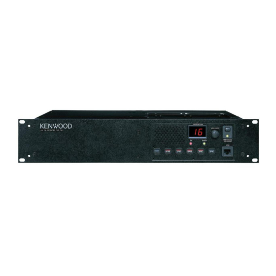
Panel (Outer)
(A62-0840-03)
Panel assy
(A62-0934-03)
GENERAL .................................................. 2
SYSTEM SET-UP ...................................... 2
OPERATING FEATURES .......................... 3
REALIGNMENT ....................................... 11
INSTALLATION ....................................... 13
MODIFICATION ....................................... 15
DISASSEMBLY FOR REPAIR ................. 16
CIRCUIT DESCRIPTION .......................... 17
SEMICONDUCTOR DATA ...................... 23
DESCRIPTION OF COMPONENTS ........ 25
PARTS LIST ............................................. 27
EXPLODED VIEW .................................... 37
PACKING ................................................. 39
ADJUSTMENT ........................................ 40
Key top
(K29-5460-02)
CONTENTS
TERMINAL FUNCTION ........................... 47
WIRING .................................................... 51
RX PLL/VCO (X58-4780-10) ................ 53
TX PLL/VCO (X58-4790-10) ................ 54
DISPLAY UNIT (X54-3330-20) ............ 55
FINAL UNIT (X45-3620-XX) ................ 59
TX-RX UNIT (X57-6260-XX) (A/2) ...... 65
TX-RX UNIT (X57-6260-XX) (B/2) ...... 71
SCHEMATIC DIAGRAM .......................... 77
BLOCK DIAGRAM ................................... 89
KES-4 (EXTERNAL SPEAKER) ............... 92
SPECIFICATIONS .................................... 93
© 2001-1 PRINTED IN JAPAN
B51-8556-00 ( N ) 1435
Knob (DC source)
(K29-9106-04)
Knob (VOL)
(K29-5389-03)
Modular jack
(E08-0543-05)
Advertisement
Table of Contents

Related Manuals for Kenwood TKR-750


Summary of Contents for Kenwood TKR-750
-
Page 1: Table Of Contents
VHF FM REPEATER TKR-750 SERVICE MANUAL © 2001-1 PRINTED IN JAPAN B51-8556-00 ( N ) 1435 Knob (DC source) (K29-9106-04) Panel (Outer) Knob (VOL) (A62-0840-03) (K29-5389-03) Panel assy Key top Modular jack (A62-0934-03) (K29-5460-02) (E08-0543-05) CONTENTS GENERAL ..........2 TERMINAL FUNCTION ......47 SYSTEM SET-UP ........ -
Page 2: General
TKR-750 GENERAL / SYSTEM SET-UP INTRODUCTION PERSONNEL SAFETY SCOPE OF THIS MANUAL The following precautions are recommended for person- nel safety : This manual is intended for use by experienced techni- • DO NOT transmit until all RF connectors are verified se- cians familiar with similar types of commercial grade com- cure and any open connectors are properly terminated. -
Page 3: Operating Features
TKR-750 OPERATING FEATURES 1. Controls and Functions 1-1. Front Panel 1 Speaker 7 Programmable Function keys Press these keys to activate their programmable func- 2 CH/STATUS Display tions. Two, 7-segment digits display the channel number or sta- tus. PF1 key (left side) -
Page 4: Operating Features
TKR-750 OPERATING FEATURES • “E2” is displayed when the channel data is not written. 2. Two 7-segment LED displays • Channel display (1~16) : While operating normally in user mode. • “E3” is displayed when PLL is unlocked. Receiver PLL unlocked = flashing BUSY LED. - Page 5 TKR-750 OPERATING FEATURES 3. Programmable Functions TKR-750 contains many Programmable Functions tabled below. Programmable Function Description AUX Out 1~5 Off AUX Out 1 to 5 ports become deactivated, respectively. AUX I/O 1~6 Off AUX I/O 1 to 6 ports become deactivated, respectively.
- Page 6 TX Disable/Enable Toggles between transmitter inhibited and transmitter enabled (normal). The following Programmable Functions are output functions used to tell the condition of the TKR-750 to an external device. The output functions can be assigned to only AUX Outputs as follows.
- Page 7 TKR-750 OPERATING FEATURES 4. Trigger Assignment The Programmable Functions described above can be assigned to PF keys, AUX input, Save on/off, Start up, and Power supply according to following table. In the last column of the table, when the Programmable Functions is assigned to any PF keys, it expresses that the LED in the PF key turns on either conditions.
- Page 8 Turns on in Disable status. None Do not turn on. The Multi Table function enables the TKR-750 to decode 5. Simplex/Duplex Operation any one of the 16 QT/DQTs pre-programmed into the Multi The Simplex/Duplex function is used to specify whether Table.
- Page 9 ADD channels is done in ascending order. audio. The TKR-750 can select the time between 140 to 200 2) Single Priority Scan : The Priority channel is set as either ms that the QT reverse burst is sent.
-
Page 10: Test Tone
15. RF Power to the Receive Audio (RA) port and a speaker if the Send CW ID to RA function is set to Yes. The TKR-750 contains 8 The TKR-750 is able to switch transmission output on a message banks for CW Message. CW Message 1 to 8 is per-channel basis. -
Page 11: Realignment
The TKR-750 repeater is programmed by using a personal 21. Start Up computer, programming interface and KPG-66D software. When the TKR-750 is first turned on or is reset, up to 3 3-2. Connection Procedure functions pre-programmed into the Start Up function are 1. - Page 12 4-1. Preface The KPG-46 is required to interface the TKR-750 to the The TKR-750 uses flash memory to allow it to be easily computer. It has a circuit in its D-sub connector (25-pin) upgraded when new features are released in the future.
-
Page 13: Installation
TKR-750 INSTALLATION 1. External Power Supply Connection TX-RX unit (B/2) control section (Rear Connectors) : See Page 3 Component side This unit has two external power supply connectors : Main DC and Backup. If an external DC power supply is connected to the main... - Page 14 TKR-750 INSTALLATION 3. External Speaker (KES-4) The TKR-750 has a internal built-in speaker (5W/8Ω), and the external speaker output from the TEST/SPKR connector (15-pin) on the rear of the radio is 4W/4Ω. Use external speaker KES-4. 3-1. Connection for the KES-4 With the TKR-750 When taking the AF output from the TEST/ Fig.
-
Page 15: Modification
TKR-750 MODIFICATION 1. Modification for Sinking the Collector Current Up 2. DC Source Switch Auxiliary output 1 and 2 can each be modified to sink up To prevent the power supply from turning off due to 600mA of the collector current. The following modification... -
Page 16: Disassembly For Repair
TKR-750 MODIFICATION / DISASSEMBLY FOR REPAIR 3. Trickle Charge for Backup Battery DISASSEMBLY FOR REPAIR If the external DC power supply is connected to the Main DC connector and a backup battery (12V rechargeable type) How to Remove the Panel Assy (ABS) -
Page 17: Circuit Description
The BPF L5/L6/L7 attenuates the unwanted signals, and 1. Outline sends only the necessary signal to the first mixer DBM A1. The TKR-750 is a VHF/FM repeater designed to operate in the frequency range of 136 to 174MHz. 2-2. First Mixer... - Page 18 TKR-750 CIRCUIT DESCRIPTION 2-4. Audio Amplifier 3. Transmitter Circuit The audio amplifier circuit is located in control section of The transmitter circuit consists of the following circuits : TX-RX unit (X57-626 B/2). The recovered audio signal ob- 3-1 microphone circuit, 3-2 modulation level adjustment cir-...
- Page 19 TKR-750 CIRCUIT DESCRIPTION 3-3. Driver and Final Power Amplifier Circuit The transmit signal is generated by the TX VCO (A2), amplified by Q11, and sent to final unit (X45-362). This am- plified signal is amplified by Q2, Q3, and Q4, and is passed to the FINAL stage.
- Page 20 TKR-750 CIRCUIT DESCRIPTION 4-2. Transmitter PLL 4. PLL Frequency Synthesizer The transmitter PLL circuit is located in VCO unit A2 (X58- The PLL frequency synthesizer circuit consists of the fol- 479) on TX-RX unit (X57-626 A/2), and consists of VCXO X3, lowing circuits : 4-1 receiver PLL circuit, 4-2 transmitter PLL VCO’s (Q350 and Q351), a single-chip PLL IC IC300, buffer...
- Page 21 TKR-750 CIRCUIT DESCRIPTION 5-5. Display Circuit 5. Control Circuit The display circuit (X54-333) contains two 7-segment The control circuit mainly located in the control section of LEDs D506, D507 (orange : see the operation manual for TX-RX unit (X57-626 B/2) consists of the following : 5-1 CPU,...
- Page 22 TKR-750 5-6. DSP 6. DC Power Supply Circuit The DSP circuit filters transmit/receive audio signal and 6-1. DC Source Switching Relay Circuit encode/decodes signaling (QT, DQT). This circuit consists 1. The final unit contains a relay (K1) for switching between of IC618, IC612, IC613, IC614, IC603, IC606, IC608, IC610, the Main DC and Backup Battery.
-
Page 23: Semiconductor Data
TKR-750 SEMICONDUCTOR DATA DSP : 320VC5402PGE (TX-RX unit IC618) Pin Function Pin No. Name Function Pin No. Name Function NC1,NC2 – Not used (No connection) BFSR1 Frame sync. for receiver input – (LRCK : 16.128kHz) DVDD – VDD for I/O pins (+3.3V) -
Page 24: Description Of Components
TKR-750 SEMICONDUCTOR DATA / DESCRIPTION OF COMPONENTS Final Unit (X45-3620-XX) Pin No. Name Function NC13 – Not used (No connection) Ref No. Part name Description HPI data bus DC amplifier TOUT0 – Not used (No connection) Thermostat EMU0 Emulator 0 (to JTAG connector) -
Page 25: Description Of Components
TKR-750 DESCRIPTION OF COMPONENTS TX-RX Unit (X57-6260-XX) Ref No. Part name Description Q600 DC switch Ref No. Part name Description Q601 Transistor DC switch IC1,2 Buffer amplifier Q602 DC switch IC3~5 Voltage regulator Q603 Transistor Inverter D/A converter Q604 DC switch... -
Page 26: Parts List
TKR-750 PARTS LIST New Parts. indicates safety critical components. L : Scandinavia K : USA P : Canada Parts without Parts No. are not supplied. Y : PX (Far East, Hawaii) T : England E : Europe Les articles non mentionnes dans le Parts No. ne sont pas fournis. - Page 27 TKR-750 PARTS LIST FINAL UNIT (X45-3620-XX) Desti- Desti- Ref. No. Address Parts No. Description Ref. No. Address Parts No. Description parts nation parts nation CK73FB1H103K CHIP C 0.010UF L9-11 L34-4520-05 AIR-CORE COIL C43,44 CK73GB1H102K CHIP C 1000PF L34-4523-05 AIR-CORE COIL...
- Page 28 TKR-750 PARTS LIST FINAL UNIT (X45-3620-XX) DISPLAY UNIT (X54-3330-20) TX-RX UNIT (X57-6260-XX) Desti- Desti- Ref. No. Address Parts No. Description Ref. No. Address Parts No. Description parts nation parts nation 02DZ5.1(Y) ZENER DIODE R511,512 RK73GB1J103J CHIP R 1/16W 1SS355 DIODE...
- Page 29 TKR-750 PARTS LIST TX-RX UNIT (X57-6260-XX) Desti- Desti- Ref. No. Address Parts No. Description Ref. No. Address Parts No. Description parts nation parts nation CC73GCH1H180J CHIP C 18PF C109 CC73GCH1H270J CHIP C 27PF CC73GCH1H220J CHIP C 22PF C110 CC73GCH1H030C CHIP C 3.0PF...
- Page 30 TKR-750 PARTS LIST TX-RX UNIT (X57-6260-XX) Desti- Desti- Ref. No. Address Parts No. Description Ref. No. Address Parts No. Description parts nation parts nation C639 CK73GB1E103K CHIP C 0.010UF C753,754 C92-0628-05 CHIP-TAN 10UF 10WV C640 C92-0628-05 CHIP-TAN 10UF 10WV C755...
- Page 31 TKR-750 PARTS LIST TX-RX UNIT (X57-6260-XX) Desti- Desti- Ref. No. Address Parts No. Description Ref. No. Address Parts No. Description parts nation parts nation CN603 E40-5887-05 PIN ASSY RK73GB1J102J CHIP R 1.0K 1/16W CN604 E40-5702-05 PIN ASSY RK73GB1J103J CHIP R...
- Page 32 TKR-750 PARTS LIST TX-RX UNIT (X57-6260-XX) Desti- Desti- Ref. No. Address Parts No. Description Ref. No. Address Parts No. Description parts nation parts nation R92-1252-05 CHIP R 0 OHM R638 RK73GB1J102J CHIP R 1.0K 1/16W R87,88 RK73GB1J102J CHIP R 1.0K...
- Page 33 TKR-750 PARTS LIST TX-RX UNIT (X57-6260-XX) Desti- Desti- Ref. No. Address Parts No. Description Ref. No. Address Parts No. Description parts nation parts nation R735 RK73GB1J333J CHIP R 1/16W R808 RK73GB1J102J CHIP R 1.0K 1/16W R736,737 RK73GB1J473J CHIP R 1/16W...
- Page 34 TKR-750 PARTS LIST TX-RX UNIT (X57-6260-XX) RX PLL/VCO (X58-4780-10) Desti- Desti- Ref. No. Address Parts No. Description Ref. No. Address Parts No. Description parts nation parts nation Q1,2 2SC3357 TRANSISTOR C359 CC73GCH1H080B CHIP C 8.0PF 2SC3356(R24) TRANSISTOR C360,361 CK73FB1C474K CHIP C 0.47UF...
- Page 35 TKR-750 PARTS LIST RX PLL/VCO (X58-4780-10) TX PLL/VCO (X58-4790-10) Desti- Desti- Ref. No. Address Parts No. Description Ref. No. Address Parts No. Description parts nation parts nation Q300,301 2SC4116(GR) TRANSISTOR L360,361 L33-1268-15 SMALL FIXED INDUCTOR Q302 2SC4215(Y) TRANSISTOR L362 L40-8271-34...
-
Page 36: Exploded View
TKR-750 TKR-750 EXPLODED VIEW : N09-2292-05 ø3 (FW) : N15-1030-46 M2.6 x 6 : N30-2606-46 D M4 x 6 : N30-4006-46 Mx14 M4 x 14 : N30-4014-46 M4 x 20 BLK : N30-4020-45 G M3 x 6 (F) : N32-3006-46... -
Page 37: Packing
TKR-750 PACKING 53 Protection bag (H25-0029-04) 49 Cushion (G13-1801-04) 59 Foot (J02-0475-05) x 2 50 Cushion (G13-1802-04) 60 Foot (J02-0492-04) x 2 54 Protetion bag (H25-0747-04) 62 Grommet (J59-0302-05) x 2 61 Hardware fixture (J21-8402-04) D Binding head machine screw (N30-4006-46) x 2... -
Page 38: Adjustment
To connect the TX-RX unit A/2 (CN14) to the TX-RX unit 150.10 150.00 146.10 146.00 B/2 (CN602) while in servicing, you can use the 36-pin flat 155.10 155.00 155.90 156.00 cable, E37-0979-05, which is available from the KENWOOD 165.10 165.00 140.10 140.00 parts center. 170.10 170.00 148.10 148.00 158.50... -
Page 39: Adjustment
TKR-750 ADJUSTMENT Measurement Adjustment Item Condition Specifications/Remarks Test- Unit Terminal Unit Parts Method equipment 1. Setting & 1) Connect the unit to a suitable DC power supply. 2) Turn the DC source switch on after connecting a PC and FPU cable to the radio. → “P.G.” appears on LED display Firmware →... - Page 40 TKR-750 ADJUSTMENT Measurement Adjustment Item Condition Specifications/Remarks Test- Unit Terminal Unit Parts Method equipment 10. TX 1) High CH (Automatically) f. counter TX-RX CN19 PC adj. frequency (A/2) 173.9975MHz (tune) 2) Low CH (Automatically) PC adj. 136.0025MHz 11. Setting 1) Insert 8 pin cable and the coaxial cable to CN16, and CN19 on TX-RX side.
- Page 41 TKR-750 ADJUSTMENT Measurement Adjustment Item Condition Specifications/Remarks Test- Unit Terminal Unit Parts Method equipment (Narrow) 3) CH : 2 (Narrow) Rear RX ANT PC adj. SSG output : 3dB below to Adjust to point of 12dB SINAD level Audio TEST/SPKR...
- Page 42 TKR-750 ADJUSTMENT Measurement Adjustment Item Condition Specifications/Remarks Test- Unit Terminal Unit Parts Method equipment ± 0.1kHz (Narrow) 2) A-low CH (TX VCO A low) MOD ANA Rear TX OUT PC adj. A-center CH (VCO A center) 2.05kHz A-high CH (TX VCO A high)
- Page 43 TKR-750 ADJUSTMENT Measurement Adjustment Item Condition Specifications/Remarks Test- Unit Terminal Unit Parts Method equipment ± 0.1kHz 27. Test tone 1) VCO-A CH (TX VCO A center) MOD ANA Rear TX ANT PC adj. deviation VCO-B CH (TX VCO B center) or...
- Page 44 TKR-750 ADJUSTMENT ATTEN 10dB MKR –42.17dB ATTEN 20dB MKR –13.50dBm ATTEN 10dB MKR –46.000dB RL –32.0dBm 10dB/ 25.00kHz RL 10.0dBm 10dB/ RL –32.0dBm 10dB/ 15.00kHz More than More than 3dB Max. 3.75kHz 3.75kHz 1.5MHz 1.5MHz 3dB Max. 5.5~7.5kHz 5.5~7.5kHz 3dB Max.
-
Page 45: Terminal Function
TKR-750 TERMINAL FUNCTION Connector Terminal Terminal I/O Terminal function Final Unit (X45-3620-XX) Name Connector Terminal Terminal I/O Terminal function STB1 Strobe data for shift register Name Clock data input TX driver input signal (Coaxial) Serial data input – – Reserved... - Page 46 TKR-750 TERMINAL FUNCTION Connector Terminal Terminal I/O Terminal function TX-RX Unit (X57-6260-XX) (B/2) : Control Section Name Connector Terminal Terminal I/O Terminal function Enable input for RX PLL Name Enable input for TX PLL CN600 O Power supply output after power...
- Page 47 TKR-750 TERMINAL FUNCTION Connector Terminal Terminal I/O Terminal function Connector Terminal Terminal I/O Terminal function Name Name – Ground O RX data output (voice & data) O Output enable for shift register I/O Programable I/O 3 TEMP High temperature detector signal input...
- Page 48 TKR-750 TERMINAL FUNCTION Connector Terminal Terminal I/O Terminal function Connector Terminal Terminal I/O Terminal function Name Name Clock input for PLL EMON External monitor switch input Reference frequency signal input “L”: Monitor on, “H”: Monitor off CN350 – Ground EPTT...
-
Page 49: Wiring
TKR-750 TKR-750 WIRING... -
Page 50: Pc Board Views
TKR-750 PC BOARD VIEWS RX PLL/VCO (X58-4780-10) RX PLL/VCO (X58-4780-10) TX PLL/VCO (X58-4790-10) TX PLL/VCO (X58-4790-10) Component side view Foil side view Component side view Foil side view J72-0749-02 A/2 J72-0749-02 A/2 J72-0750-02 A/2 J72-0750-02 A/2 R368 C379 C379 R368... -
Page 51: Display Unit (X54-3330-20)
TKR-750 PC BOARD VIEWS DISPLAY UNIT (X54-3330-20) Component side view J72-0756-02 A/2 J72-0756-02 B/2 CN601 VR601 C603 C606 D506 D507 C602 S507 CP502 CP504 D602 D601 CP501 CP503 MAIN DC BACKUP R601 D505 HOOK J601 IC504 IC505 R543 R517 R606... - Page 52 TKR-750 PC BOARD VIEWS DISPLAY UNIT (X54-3330-20) Foil side view J72-0756-02 A/2 J72-0756-02 B/2 CN601 VR601 D507 D506 C606 C603 C602 S507 CP504 CP502 D602 D601 CP503 CP501 BACKUP MAIN DC R601 D505 HOOK J601 IC505 IC504 R543 R517 R606...
- Page 53 TKR-750 PC BOARD VIEWS FINAL UNIT (X45-3620-XX) -10 : K,E -11 : K2 Component side view CN8 GND CN6 MAIN DC J72-0754-12 A/2 (BLACK) (RED) CN7 BACKUP J72-0754-12 B/2 (ORANGE) C118 CHARGE C141 C142 C140 C106 TX IN Component side Ref No.
-
Page 54: Final Unit (X45-3620-Xx)
TKR-750 PC BOARD VIEWS FINAL UNIT (X45-3620-XX) -10 : K,E -11 : K2 Foil side view J72-0754-12 A/2 J72-0754-12 B/2 C108 C109 C110 Component side Ref No. Address Ref No. Address Ref No. Address Pattern 1 Pattern 2 Pattern 3... - Page 55 TKR-750 PC BOARD VIEWS FINAL UNIT (X45-3620-XX) -10 : K,E -11 : K2 Component side view + Foil side CN8 GND CN6 MAIN DC J72-0754-12 A/2 (BLACK) (RED) CN7 BACKUP J72-0754-12 B/2 (ORANGE) C118 CHARGE C141 C142 C140 C108 C106...
-
Page 56: Tx-Rx Unit (X57-6260-Xx) (A/2)
TKR-750 PC BOARD VIEW TX-RX UNIT (X57-6260-XX) (A/2) -10 : K,E -11 : K2 Component side view J72-0757-01 A/2 CN16 CN19 GND2 8CLT GND1 CN18 TP102 TX CV A2 : TX VCO (X58-479) C137 C139 C212 CN15 C213 NARROW C196... -
Page 57: Tx-Rx Unit (X57-6260-Xx) (B/2)
TKR-750 PC BOARD VIEW TX-RX UNIT (X57-6260-XX) (A/2) -10 : K,E -11 : K2 Foil side view J72-0757-01 A/2 R15 R16 GND2 R106 C127 + R148 R159 C129 R121 C167 C199 C123 GND1 C120 R122 C131 R151 R152 R153 R130... - Page 58 TKR-750 PC BOARD VIEW TX-RX UNIT (X57-6260-XX) (A/2) -10 : K,E -11 : K2 Component side view + Foil side J72-0757-01 A/2 CN16 CN19 R106 GND2 C127 R148 R159 C129 R121 C199 C167 C123 C120 GND1 CN18 8CLT R122 TP102...
- Page 59 TKR-750 PC BOARD VIEW TX-RX UNIT (X57-6260-XX) (B/2) -10 : K,E -11 : K2 Component side view C806 C800 R781 IC627 IC630 C817 C789 L606 IC629 L607 C826 C801 + 3.3D C785 C795 L601 C798 D600 L604 C814 C613 R654...
- Page 60 TKR-750 PC BOARD VIEW TX-RX UNIT (X57-6260-XX) (B/2) -10 : K,E -11 : K2 Foil side view Q602 Q601 CN602 C784 C787 R616 X600 R754 R606 IC600 Q606 R762 C783 D627 Q611 Q609 Q603 C635 C634 C629 C791 R811 C731...
- Page 61 TKR-750 PC BOARD VIEW TX-RX UNIT (X57-6260-XX) (B/2) -10 : K,E -11 : K2 Component side view + Foil side Q601 Q602 CN602 C806 C800 C784 R781 C787 IC627 IC630 C817 C789 R616 X600 L606 R754 R606 IC600 Q606 IC629...
- Page 62 TKR-750 Note : Components marked with a dot (·) are parts of pattern 1. CIRCUIT DIAGRAM...
- Page 63 TKR-750 CIRCUIT DIAGRAM Note : Components marked with a dot (·) are parts of pattern 1.
- Page 64 TKR-750 Note : Components marked with a dot (·) are parts of pattern 1. CIRCUIT DIAGRAM...
-
Page 65: Block Diagram
TKR-750 TKR-750 TKR-750 BLOCK DIAGRAM... -
Page 66: External Speaker)
TKR-750 KES-4 (EXTERNAL SPEAKER) When Using an External Speaker 1. Make sure the unit‘s power is tuned off. 2. When using the external speaker, remove the jumper lead from the connector, and attach the speaker cable. 3. When not using the external speaker, replace the jumper lead and insert the connector into the speaker jack (pin9 and 12). - Page 67 TKR-750 SPECIFICATIONS (K,K2 TYPE) GENERAL Frequency Range ........ K : 146 to 174MHz K2 : 136 to 150MHz Number of Channels ......16 channel Channel Spacing ......... Wide : 30kHz, 25kHz Narrow : 15kHz, 12.5kHz (PLL channel stepping 2.5kHz/5kHz/6.25kHz/7.5kHz) Operating Voltage ....... 13.6V DC± 15% Current Drain Standby ..........
- Page 68 Mechelsesteenweg 418 B-1930 Zaventem, Belgium KENWOOD ELECTRONICS FRANCE S.A. 13, Boulevard Ney, 75018 Paris, France KENWOOD ELECTRONICS U.K. LIMITED KENWOOD House, Dwight Road, Watford, Herts., WD1 8EB United Kingdom KENWOOD ELECTRONICS EUROPE B.V. Amsterdamseweg 37, 1422 AC Uithoorn, The Netherlands KENWOOD ELECTRONICS ITALIA S.p.A.