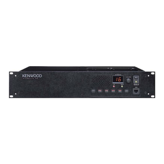
Kenwood TKR-751 Service Manual Supplement
Vhf fm repeater
Hide thumbs
Also See for TKR-751:
- Modification information (18 pages) ,
- Instruction manual (15 pages) ,
- Brochure & specs (2 pages)
Advertisement
Quick Links
Document Copyrights
Copyright 2006 by Kenwood Corporation. All rights reserved.
No part of this manual may be reproduced, translated, distributed, or transmitted in any
form or by any means, electronic, mechanical, photocopying, recording, or otherwise, for
any purpose without the prior written permission of Kenwood.
Disclaimer
While every precaution has been taken in the preparation of this manual, Kenwood
assumes no responsibility for errors or omissions. Neither is any liability assumed for
damages resulting from the use of the information contained herein. Kenwood reserves
the right to make changes to any products herein at any time for improvement purposes.
Advertisement

Summary of Contents for Kenwood TKR-751
- Page 1 Kenwood. Disclaimer While every precaution has been taken in the preparation of this manual, Kenwood assumes no responsibility for errors or omissions. Neither is any liability assumed for damages resulting from the use of the information contained herein. Kenwood reserves...
-
Page 2: Table Of Contents
This supplement to the service manual is available for products with serial number 60700001 or later. This service manual contains a parts list, schematic diagrams and PC board of a new final unit for the TKR-751. Since the adjustment procedure is the same as before, refer to the service manual (B51-8683-00) the TKR-751 for items not provided in this service manual. -
Page 3: Modification
3. Single Antenna 1. Solder the prepared coaxial cable to the final unit. The TKR-751 can be used as a base station by sharing an 2. Connect the pin connector of the coaxial cable to CN18 of external antenna connector for both transmitting and receiv- the TX-RX unit. -
Page 4: Parts List
Les articles non mentionnes dans le Parts No. ne sont pas fournis. Y : AAFES (Europe) X : Australia M : Other Areas Teile ohne Parts No. werden nicht geliefert. TKR-751 (Y54-322X-XX) FINAL UNIT (X45-3732-71) Desti- Desti- Ref. No. Address Parts No. - Page 5 TKR-751 PARTS LIST FINAL UNIT (X45-3732-71) Desti- Desti- Ref. No. Address Parts No. Description Ref. No. Address Parts No. Description parts nation parts nation R92-2559-05 CHIP R 1/2W R23,24 RK73FB2A104J CHIP R 100K 1/10W RK73GB1J473J CHIP R 1/16W RK73GB1J101J CHIP R...
-
Page 6: Exploded View
TKR-751 EXPLODED VIEW D M4 x 14 : N30-4014-46 M3 x 8 : N67-3008-46 N M2.6 x 6 (Br-Tap) : N87-2606-46 M3 x 6 (Br-Tap) : N87-3006-46 Px11 Final (A/2) Final (B/2) Parts with the exploded numbers larger than 700 are not supplied. -
Page 7: Pc Board
TKR-751 PC BOARD FINAL UNIT (X45-3732-71) Component side view (J72-0970-19) CN8 GND CN6 MAIN DC (BLACK) (RED) CN7 BACKUP (ORANGE) Back up battery Main DC C118 CHARGE FAB 1 C106 C143 TX IN J72-0970-19 (B/2) Ref. No. Address Ref. No. Address... - Page 8 TKR-751 PC BOARD FINAL UNIT (X45-3732-71) Component side view (J72-0970-19) J72-0970-19 (A/2) C164 C118 C165 C173 CN53 ANT SW Component side Layer 1 Layer 2 Layer 3 Layer 4 Foil side...
- Page 9 TKR-751 TKR-751 PC BOARD PC BOARD FINAL UNIT (X45-3732-71) Component side view (J72-0970-19) FINAL UNIT (X45-3732-71) Component side view (J72-0970-19) J72-0970-19 (A/2) CN8 GND CN6 MAIN DC (BLACK) (RED) C164 CN7 BACKUP (ORANGE) Back up battery Main DC C118 CHARGE...
- Page 10 TKR-751 PC BOARD FINAL UNIT (X45-3732-71) Foil side view (J72-0970-19) J72-0970-19 (A/2) C174 Ref. No. Address Ref. No. Address Ref. No. Address...
- Page 11 TKR-751 PC BOARD FINAL UNIT (X45-3732-71) Foil side view (J72-0970-19) C103 C168 Back up battery Main DC C108 C109 C110 J72-0970-19 (B/2) Component side Layer 1 Layer 2 Layer 3 Layer 4 Foil side...
- Page 12 TKR-751 TKR-751 PC BOARD PC BOARD FINAL UNIT (X45-3732-71) Foil side view (J72-0970-19) FINAL UNIT (X45-3732-71) Foil side view (J72-0970-19) J72-0970-19 (A/2) C103 C168 Back up battery Main DC C174 C108 C109 C110 J72-0970-19 (B/2) Component side Ref. No. Address Ref.
-
Page 13: Schematic Diagram
TKR-751 SCHEMATIC DIAGRAM FINAL UNIT (X45-3732-71) (A/2) T:8.04V R:0V T:7.84V R:0V 350mW C143 1000p 1000p 1000p 2SC3357 2SC3356 (R24) THERMAL T:1.15V T:0.73V SENSE R:0V R:0V Q2,3 1SS226 RF AMP DC SWITCH SURGE VOLTAGE ABSORPTION THERMOSTAT 2SC4116(Y) REGULATOR T:13.02V 100k R:13.65V... - Page 14 TKR-751 SCHEMATIC DIAGRAM FINAL UNIT (X45-3732-71) (A/2) 3.0A FINAL AMP C160 1000p 120p TX ANT 1000p 1000p DRIVE 100k 100k D4,5 RF SWITCH RF DETECTOR MA4PH633 T:5.18V VOLTAGE R:0V REFERENCE DC AMP TA75W01FU IN2+ 1000p IN1+ IN2- 100k IN1- OUT-B...
- Page 15 FINAL UNIT (X45-3732-71) (A/2) 3.0A T:8.04V R:0V T:7.84V R:0V FINAL AMP C160 1000p 350mW C143 120p TX ANT 1000p 1000p 1000p 1000p 1000p 2SC3356 2SC3357 (R24) DRIVE 100k 100k THERMAL D4,5 RF SWITCH T:1.15V T:0.73V SENSE RF DETECTOR R:0V R:0V MA4PH633 T:5.18V Q2,3...
- Page 16 Leuvensesteenweg 248 J, 1800 Vilvoorde, Belgium KENWOOD ELECTRONICS FRANCE S.A. 13, Boulevard Ney, 75018 Paris, France KENWOOD ELECTRONICS U.K. LIMITED KENWOOD House, Dwight Road, Watford, Herts., WD18 9EB United Kingdom KENWOOD ELECTRONICS EUROPE B.V. Amsterdamseweg 37, 1422 AC Uithoorn, The Netherlands KENWOOD ELECTRONICS ITALIA S.p.A.


