Table of Contents
Advertisement
Quick Links
Copyright C Hitachi High-Technologies Corporation 2010.
All rights reserved. Printed in Japan.
INSTRUCTION MANUAL
MODEL TM3000
TABLETOP MICROSCOPE
・Before using the instrument, read the safety instructions and
precautions carefully.
・Be sure to follow the instructions and warning of instruction manual
and warning label.
・Keep this manual in a safe place nearby so it can be referred to
whenever needed.
FOR
Part No. 55E-9001-1 HT-R (H-HMS)
Advertisement
Table of Contents

Related Manuals for Hitachi TM3000


Summary of Contents for Hitachi TM3000
- Page 1 ・Be sure to follow the instructions and warning of instruction manual and warning label. ・Keep this manual in a safe place nearby so it can be referred to whenever needed. Copyright C Hitachi High-Technologies Corporation 2010. All rights reserved. Printed in Japan. Part No. 55E-9001-1 HT-R (H-HMS)
- Page 2 NOTICE: 1. Information contained in this document is subject to change without notice for improvement. 2. This manual is copyrighted by Hitachi High-Technologies Corporation with all rights reserved. No part of this manual may be reproduced, transmitted or disclosed to a third party in any form or by any means without the express written permission of Hitachi High-Technologies Corporation.
-
Page 3: Preface
PREFACE Thank you for your recent purchase of a TM3000 Tabletop Microscope. The TM3000 Tabletop Microscope (“TM” for short) is designed to observe and evaluate specimens that are prepared specifically for the TM, using an electron beam accelerated to 5 or 15kV as a light source. - Page 4 ● First, please read the sections on “IMPORTANT” and “For the Safe Handling of the System” provided at the beginning of this Instruction Manual. List of Abbreviations Abbreviations that appear frequently in this Instruction Manual and their full spellings are given below: PC : Personal Computer HV : High Voltage...
-
Page 5: Important
Product Warranty Product Warranty Hitachi High Technologies Corporation (“HHT”) warrants that the Model TM3000 Tabletop Microscope is free of defect, either in material or manufacturing, based on the specifications provided in this Instruction Manual, provided that the system is used in compliance with the contents of the Instruction Manual. - Page 6 A system failure arising from the corrosion of its electrical circuits or deterioration of its optical elements due to the use of the system under a strongly corrosive atmosphere, such as chlorine gas, or in a dusty environment. A system failure arising from the use of hardware, software, or supplies that are not provided by HHT.
-
Page 7: Installation, Relocation, And After Service
Third-Party Intellectual Property HHT disclaims any liability for claims made by a third party, such as on products made by using a system delivered by HHT or an affiliate thereof, or on patents owned by a third party with respect to the use of a delivered system. -
Page 8: Workshop And Training For Customers
Workshop and Training for Customers For the safe and accurate use of the system, HHT provides workshop and training, either at HHT’s facility or on an on-site visit basis. For procedures for receiving such training, please consult the sales department that handles your account (it will be on a charge basis). System Life The life length of the system is seven (7) years from the commencement of its use, provided that the system is properly maintained in terms of the periodic maintenance and inspection,... -
Page 9: Miscellaneous
Miscellaneous Leaked X-Rays Unlike equipment that emits X-rays to the outside for use, electron microscopes are not subject to filing requirements under the Radiation Damage Prevention Act or the Ionizing Radiation Damage regulations. The International Committee on Radiation Protection (ICRP), identify electron microscopes, as well as home television sets, as potential, undesirable sources of X-rays as byproducts. -
Page 10: For The Safe Handling Of The System
For the Safe Handling of the System Before using the Tabletop Microscope, carefully read the safety precautions provided below, and please be sure to understand them thoroughly. Precautions on human safety are displayed using the following headers combining the safety alert symbol and the phrases “DANGER”, “WARNING”, and “CAUTION”: :... - Page 11 ・ When using the chemical such as the reagent, confirm properties of the material and information on handling (MSDS etc.) and handle it properly. ・ If any problem arises with respect to the system, please contact the Sales Department that handles your account or a maintenance service company designated by HHT.
-
Page 12: General Precautions On Safety
For the Safe Handling of the System General Precautions on Safety Notes that have not been described in the instruction manual are shown below. WARNING Accident by using the device continuously with abnormal condition • If an abnormal noise, a strange odor, or the generation of fumes occurs when the system is being used, immediately turn it off, and unplug the power cord from the outlet. - Page 13 For the Safe Handling of the System Warnings Provided in the Instruction Manual Notes that have been described to the manual and their description places are shown as follows. WARNING Use in humid and dusty place • Do not use the system near a sink, a humidifier, or any place near water, in a humid basement room, or a dusty place or a place subject to fumes.
- Page 14 For the Safe Handling of the System Warnings Provided in the Instruction Manual (continued) WARNING Injury by heavy load • The system is a heavy object weighing approximately 63 kg. Install the system on a table with a minimum load bearing capacity of 100 kg. Installing it on a table with an inadequate load bearing capacity can cause the table to break, which can result in unexpected injury beyond damage to the system.
- Page 15 For the Safe Handling of the System Warnings Provided in the Instruction Manual (continued) CAUTION Injury from Being Pinched • The specimen stage's weight is approximately 5 kg. It might cause injury when operating it grasping the parts other than the handle. When changing specimens, securely grasp the handle, and use caution so that your hands will not be pinched.
-
Page 16: Warning And Caution Labels On The System
P/N 55E-2764 WARNING Hazardous voltage inside Can cause death or severe injury. Do not remove the cover. P/N 52E-4125 Locations of WARNING and CAUTION Labels on the TM3000 Main Unit (on the Sides) SAFETY - 7... - Page 17 For the Safe Handling of the System WARNING and CAUTION Labels on the System (continued) WARNING WARNING Hazardous voltage inside Can cause death or severe injury. Hazardous voltage inside Do not remove the cover. Can cause death or severe injury. P/N 52E-4125 Do not remove the cover.
-
Page 18: To Avoid Serious Property Damage Or Damage To The System
For the Safe Handling of the System To Avoid Serious Property Damage or Damage to the System NOTICE About the Power Supply (1) Make sure the power supplied to the Tabletop Microscope is AC 100-240V (Min. 90V, Max. 250V), 500 VA or higher (50/60Hz). Voltage fluctuations and superposed noise on the power line can adversely affect the main unit. -
Page 19: About Power Outages
For the Safe Handling of the System To Avoid Serious Property Damage or Damage to the System (continued) NOTICE About Power Outages An instantaneous voltage sag caused by a power outage or lightening can potentially damage the basic software, the application software, or data. As a countermeasure against instantaneous voltage sag, the use of the system with a PC battery mounted is recommended. -
Page 20: About The Computer Virus
For the Safe Handling of the System To Avoid Serious Property Damage or Damage to the System (continued) NOTICE About the Computer Virus If a program or data suddenly becomes corrupt, an unexpected operation occurs, or an abnormal screen appears, the infection of the PC by a computer virus must be suspected. The computer virus refers to a malicious program that surreptitiously invades the PC, runs the PC uncontrollably, or damages data. -
Page 21: About Network Connection
For the Safe Handling of the System To Avoid Serious Property Damage or Damage to the System (continued) NOTICE About Network Connection For network connection, the PC is equipped with an Ethernet port. As connecting to the network through the use of Ethernet requires sufficient knowledge on the network environment, perform such a connection by consulting your network administrator. -
Page 22: For The Proper Use Of The System While Avoiding Minor Damage To It
For the Safe Handling of the System For the Proper Use of the System While Avoiding Minor Damage to It Installing the Control Application If the control application is installed using a privilege other than the administrator privilege, when a user logs in by using power user or general user privileges, the control application may fail to run properly. - Page 23 For the Safe Handling of the System For the Proper Use of the System While Avoiding Minor Damage to It (continued) Precautions on Operating the System When leaving the system unattended, turn off the Start button. Do not use large quantities of chemicals (such as conducting paste) that fix specimens onto the specimen stub.
-
Page 24: Table Of Contents
Contents PREFACE ........................... 1 ABOUT THIS INSTRUCTON MANUAL ................1 IMPORTANT ....................IMPORTANT-1 Product Warranty.................... IMPORTANT-1 Installation, Relocation, and After Service............IMPORTANT-3 Workshop and Training for Customers............IMPORTANT-4 System Life..................... IMPORTANT-4 Disposal......................IMPORTANT-4 Miscellaneous ....................IMPORTANT-5 For the Safe Handling of the System ............SAFETY- 1 General Precautions on Safety ................ -
Page 25: Precautions On Operating The System
2.3.4 Upgrade of Instruction Manual ..............2- 62 2.3.5 Upgrade (Repair) of Instruction Manual............2- 66 2.3.6 Downgrade of Instruction Manual............... 2- 67 2.4 About TM3000 Setup Disk (A Brief Explanation /Summary) ........2- 68 2.4.1 Installing an Application ................2- 69 - ii -... - Page 26 2.4.2 Upgrade for TM3000 Application..............2- 70 2.4.3 Output Log Data..................2- 71 2.4.4 About TM3000 Application ................. 2- 71 2.4.5 Exit......................2- 71 3 SYSTEM CONFIGURATION..................3- 3.1 System Configuration .................... 3- 3.2 Part Names ......................3- 3.2.1 Main Unit....................3- 3.2.2 Diaphragm Pump ..................
- Page 27 4.3.6 Setting Menu....................4- 48 4.3.7 Stage Menu ....................4- 50 4.3.8 Maintenance Menu..................4- 53 4.3.9 Help Menu ....................4- 54 4.3.10 Start/Stop Button..................4- 55 4.3.11 View Mode Selection Button ..............4- 57 4.3.12 Image Mode Button.................. 4- 58 4.3.13 Observation Condition Selection Button ...........
- Page 28 5.4 Objective Aperture Replacement................5- 23 5.5 Error Messages ..................... 5- 27 5.5.1 Messages That are Displayed When a Given Application is Started ..5- 27 5.5.2 Initial Startup Window (During Initialization) ..........5- 29 5.5.3 Normal Observation Screen ............... 5- 31 5.5.4 Wait Message Window................
-
Page 29: Precautions On Handling
PRECAUTIONS ON HANDLING For safety, please comply with the following precautions: 1. Precautions on Using the System WARNING (1) Do not remove the cover from the main unit. Maximum voltages of AC 240 V and DC 15 kV prevail inside the main unit, potentially causing severe injury or death from electric shock when touched. -
Page 30: Emergency Action
6. Electromagnetic Wave Interference The TM3000 is in compliance with EN Standard EN61326-1:2006 Class A(except for PC). Do not install the system near a device in which data is subject to adverse impact by electromagnetic noise within the tolerance value of the Standard. -
Page 31: Specifications And Installation Conditions
By downsizing a conventional electron microscope and simplifying the operations, the Tabletop Microscope invites users who have never touched an electron microscope before to use it as a handy tool. The TM3000 represents considerable improvements in performance and functionality over the previous Model TM-1000 Tabletop Microscope, offering a truly easy to use high-performance system. -
Page 32: Features
1.2 Features The TM3000 provides the following main features. 1. A compact desktop electron microscope. 2. Provides a great focal depth and permits high magnification observations when compared with an optical microscope. 3. Elimination of cumbersome preparation of samples. 4. The capacity to accept the mounting of specimens up to 70 mm across and 50 mm thick. -
Page 33: Specifications
1.3 Specifications Table 1.3 Specifications Item Product Specifications 1 Accelerating voltage 5 kV, 15 kV Magnification 15 to 30000x (image display magnification: number of steps: 40 (※1) ) (digital zoom 2x, 4x), max. observation range: 3.5 mm on an edge The minimum magnification depends on the accelerating voltage, D (※2), and the screen size. -
Page 34: Installation Conditions
Frequency ≦ 7 Hz, 4.0 µm p-p or less 7 Hz < frequency ≦ 10 Hz, 1.5 µm p-p or less 10 Hz < frequency, 2.0 cm/s or less Allowable stray magnetic field for the TM3000 Magnetic field DC magnetic field AC magnetic field... - Page 35 ・ The customer must not transfer the device. When transferring the device is required, contact the Hitachi's service engineer or qualified engineers trained and certified by Hitachi. WARNING : As a rule, do not move the diaphragm pump because it is a heavy load of 4.5 kg.
- Page 36 For layout, see Figure 1.4 below. Power supply & grounding Grounded 3P power cable (3 m) Diaphragm pump USB cable ※ Recommended Table layout Notebook PC 2P power cable (2.5 m) Main unit 1000 min. Units: mm ※ The Chair is not included in the size Figure 1.4 Layout Diagram 1 - 6...
-
Page 37: Pc Specifications
1.5 PC Specifications Table 1.5 PC Specifications Item Details Recommended PC specifications : Windows Ⓡ 7 Professional (32 bit, English Version) : Intel Ⓡ Core™ 2Duo T8700 (or a compatible CPU) or greater Memory capacity : 2 GB minimum Display resolution : 1280 x 800 pixels (1,677,000 colors) WXGA Display : 15.4-inch Interface connector : USB2.0... -
Page 38: Installation And Setup
2 INSTALLATION AND SETUP 2.1 Connecting to the PC Connect the PC to the main unit as shown in Figure 2.1 1. Connect the USB cable protruding from the main unit to the USB port on the back of the PC. -
Page 39: Setting Up The Pc
2.2 Setting up the PC 2.2.1 Installing an Application NOTE : Before installing an application, check the following precautions: 1. For installation, log on as Administrator. 2. Install the application before connecting the system main unit to the PC via the USB. - Page 40 4. TM3000 Setup Tools is run automatically. If User Account Control is displayed on the window, click [ALLOW]. Click Figure 2.2.1-3 User Account Control 5. Type Serial Number in the dialogue box, and click [OK]. Figure 2.2.1-4 Passwords 6. Serial No. is on the seal of back of main unit .
- Page 41 7. Displayed the menu of TM3000 Setup Tools. Click [Installation for TM3000 application] on that window. Click Figure 2.2.1-6 The Main Menu of TM3000 Setup Tools 8. The following window appears. Click the button [Installation of application program]. Click Figure 2.2.1-7 Installation for TM3000 Application...
- Page 42 NOTE : If the application is already installed, the window shown below appears. If this is the case, click [OK], uninstall the application, and then re-install it. (For details on the uninstall process, see [2.2.9 Uninstalling an application]). Figure 2.2.1-8 Message 9.
- Page 43 Click Figure 2.2.1-12 User Information Entry Window NOTE : If the TM3000 application is for all login users on the PC, select [Anyone who uses this computer (all users)]. The [Only for me] option excludes users other than the one who is performing the installation from using the TM3000 application.
- Page 44 13. The following window appears. Click [Install] button. Click Figure 2.2.1-13 Install Start Window 14. The following window appears. (Do not click the [Cancel;] button.) Figure 2.2.1-14 Application Install Window (a) 2 - 7...
- Page 45 15. When the window shown in Figure 2.2.1-15 (Windows Security) appears, click [Install this driver software anyway]. Click Figure 2.2.1-15 Application Install Window (b) 16. Operation stops with the following windows in a few minutes. Figure 2.2.1-16 Application Install Window (c) 2 - 8...
- Page 46 17. This is because a message of Figure 2.2.1-19 is covered on the back of the above window (Figure2.2.1-16). In this case because [Attach Your device] is displayed on task bar, and click it. Click Figure 2.2.1-17 Task Bar (Windows VISTA) Click Figure 2.2.1-18 Task Bar (Windows 7) 18.
-
Page 47: Installing An Instruction Manual
2.2.2 Installing an Instruction Manual 1. Install an instruction manual. Click the button [Installation for TM3000 application]. Click Figure 2.2.2-1 The Main Menu of TM3000 Setup Tools 2. The following window appears. Click the button [Installation of the instruction manuals]. - Page 48 NOTE : If the Instruction Manual is already installed, the window shown below appears. If this is the case, click [OK], uninstall the Instruction Manual, and then re-install it. (For details on the uninstall process, see [2.2.12 Uninstalling an Instruction Manual]).
- Page 49 Click Figure 2.2.2-7 User Information Entry Window NOTE : If the TM3000 application is for all login users on the PC, select [Anyone who uses this computer (all users)]. The [Only for me] option excludes users other than the one who is performing the installation from using the TM3000 application.
- Page 50 7. The window shown in Figure 2.2.2-8 appears. Click the [Install] button. Click Figure 2.2.2-8 Instruction Manual Install Window 8. The following window appears. (Do not click the [Cancel;] button.) Figure 2.2.2-9 Manual Install Window 2 - 13...
- Page 51 9. The following [InstallShield Wizard Completed] is displayed. Click [Finish] button. Click Figure 2.2.2-10 InstallShield Wizard Completed Window 2 - 14...
-
Page 52: Setup Of System Files
2.2.3 Setup of System Files 1. Setup System Files. Click the button [Installation for TM3000 application]. Click Figure 2.2.3-1 The Main Menu of TM3000 Setup Tools 2. The following window appears. Click the button [Setup of system files]. Click Figure 2.2.3-2 Installation Menu of TM3000 Setup Tools... - Page 53 3. The following message is displayed, after finishing installation of System Files. Figure 2.2.3-3 Message of Finishing Installation of System Files 4. Click the button [Exit] of Installation menu of TM3000 Setup Tools. Click Figure 2.2.3-4 Installation for TM3000 Application 5.
-
Page 54: Checking The Installation Of Application
1. Verify that a [TM3000] shortcut exists on Desktop. Figure 2.2.4-1 TM3000 Shortcut Icon 2. Verify that [TM3000] has been added to the Start program menu. Figure 2.2.4-2 Checking the Application 3. The files containing the application are installed in a folder named [C:\Program Files\TM3000\]. -
Page 55: Installing The Usb Driver Software
2.2.5 Installing the USB Driver Software Installing the USB software has to be done after having installed a TM3000 application program. 1. With a USB cable, connect the system main unit to the PC. Keep turning off the system of main unit. -
Page 56: Checking The Driver Software
2.2.6 Checking the Driver Software 1. From [Control Panel], open [Device Manager]. Figure 2.2.6-1 Device Manager Icon ※ If Device Manager fails to appear, click [Classic View] to display it. 2. The window (User Account Control) shown in Figure 2.2.6-2 appears. Click [Continue]. Click Figure 2.2.6-2 User Account Control Window 2 - 19... - Page 57 3. Device Manager is displayed. On Device Manager, verify that the [SemUsb Device] exists. If [SemUsb Device] does not exist, re-install the USB driver. Figure 2.2.6-3 Device Manager Window 4. Close the Device Manager. 2 - 20...
-
Page 58: Screen Settings
2.2.7 Screen Settings ® 1. In the Case of Windows 1a. Click the lower left of desktop button, click [Control Panel]. Click Figure 2.2.7-1 Open the Control Panel 1b. Click [Small icons] of View by: [Category] on Control panel. Click Figure 2.2.7-2 Control Panel 2 - 21... - Page 59 1c. Click [Personalization]. Click Figure 2.2.7-3 Adjust your computer’s settings 1d. Down the scrollbar, and click [Windows 7 Basic]. Scroll down Figure 2.2.7-4 Personalization 2 - 22...
- Page 60 1e. The window is B/W image in a few seconds, and return. Confirm [Windows color] is changed to [Windows 7 Basic], [Screen saver] is changed to [None]. Click [Screen saver]. Click Figure 2.2.7-5 Setting of Personalization NOTE : It is recommend use by the setting mentioned above. Especially, there is the case that does not some function smoothly when using [Windows Aero] function.
- Page 61 1g. [Power Options] window appears. Confirm [Plans shown on the battery meter] is [Balance], and click [Change plan settings]. Click Figure 2.2.7-7 Select a power plan 1h. [Edit Plan Settings] window appears. Change [Turn off the display], [Put the computer to sleep] and [On battery] [Plugged in] both to [Never].
- Page 62 1i. Change a plan to [Power saver], and Click [Change plan settings]. Change the setting to [Never] in a procedure same as 1h. Click the [Save changes]. Click 1 Click 2 Figure 2.2.7-9 Select a Power Plan Again 1j. Back to [Power Options], and Click [Choose what closing the lid does]. Click Figure 2.2.7-10 Select a Power Plan Again 2 - 25...
- Page 63 1k. The following window appears. Change the setting to [Shut down] of When I press the power button: Change the setting to [Do nothing] of When I close the lid: Set same condition to [On battery] and [Plugged in]. After setting, click [Save changes]. Change to [Shut down] Change to [Do nothing] Click...
- Page 64 1l. Return to [Select a power plan], click [Personalization] and click [Display]. Click Figure 2.2.7-12 Select a Personalizations Click Figure 2.2.7-13 Click [Display] 2 - 27...
- Page 65 1m. The following window appears. Click [Set custom text size (DPI)]. Click Figure 2.2.7-14 Display 1n. Confirm the setting is follow (9point Segoe UI at 96 pixels per inch), click [OK]. Figure 2.2.7-15 Custum DPI Setting 1o. Back to Display, Click [Adjust resolution]. Click Figure 2.2.7-16 Click [Adjust resolution] 2 - 28...
- Page 66 1p. Confirm the setting is follow (1280x800 (Recomended)), click [OK]. Figure 2.2.7-17 Screen Resolution With the above setup of the PC is completion. Refer to [2.2.1 Installing an Application] about installation of TM3000 application. 2 - 29...
- Page 67 ® 2. In the Case of Windows VISTA 2a. From [Control Panel], open [Personalize]. Figure 2.2.7-18 Personalize Icon 2b. The Personalization menu appears. Click [Display Settings]. Click Figure 2.2.7-19 Personalize Window 2 - 30...
- Page 68 2c. A Display Settings dialog appears. Select a [1280×800 pixel] resolution and a [maximum (32-bit)] color. Click the [Apply] button and the [OK] button to close the window. If the resolution and the color are already set as indicated above when the Display Settings dialog is opened, simply click the [OK] button to close the window.
- Page 69 2e. A DPI scale is displayed. Verify that [Default scale (96 DPI) – fit more information] is selected. Click the [OK] button to close the window. If a DPI scale different from the above is selected, change it, and click the [Apply] button, and then the [OK] button. Click Click to change Figure 2.2.7-22 DPI Scaling Window...
- Page 70 Click Click Figure 2.2.7-23 Screen Saver Settings 2g. From [Power Management], click [Change power settings ….]. A power options menu appears. Click [Change plan settings] for the currently selected mode. Click Figure 2.2.7-24 Power Options Window 2 - 33...
- Page 71 2h. The [Edit Plan Settings] menu appears. On all of the options, [Turn off the display] and [Put the computer to sleep], select [Never], and click the [Save changes] button. Click Figure 2.2.7-25 Change Settings for the Plan Window NOTE : Specify the above settings in each of the Balanced, Power Saver, and High Performance modes.
- Page 72 2j. The System Settings menu appears. Set [When power button is pressed] to [Run on battery], [When connected to power supply] to [Shut down], [When lid is closed] to [Run on battery], and [When connected to power supply] to [Do nothing]; click [Save changes]. When finished with saving the changes, close the Power Options window and the Screen Saver window.
- Page 73 2k. On the Personalization menu, click [Window Color and Appearance]. A Window color and appearance menu appears. Click Figure 2.2.7-28 Window Color and Appearance Window 2l. On the Window Color and Appearance menu, click [Open the classic style [Appearance] property to set detailed color options]. The Appearance Settings window appears. For color scheme, select [Windows Vista basic], and click the [Apply] button.
- Page 74 NOTE : For the application, the uses of the above settings are recommended. The use of the [Windows Aero] feature can potentially cause problems, such as slow observation window drawing or a failure to support normal observation. 2m. Close the Personalization menu. 2 - 37...
-
Page 75: Changing The Default Input Language
2.2.8 Changing the Default Input Language 1. Click on the [Option] button of the Language Bar. Figure 2.2.8-1 [Option] Button of the Language Bar 2. From the sub menu, click on [Settings…]. The Text Services and Input Languages dialog will be displayed. Figure 2.2.8-2 Languages Dialog 2 - 38... - Page 76 3. Click on the [Add…] button. The Add Input Language dialog will be displayed. Figure 2.2.8-3 Add Input Language-General Dialog 4. From the list, select [Japanese (Japan)] – [Keyboard] – [Microsoft IME] and click on the [OK] button. Figure 2.2.8-4 Add Input Language Dialog 2 - 39...
- Page 77 5. From the pull down list of the “Default input language” in the “Text Services and Input Languages” dialog, select [Japanese (Japan) – Microsoft IME]. Figure 2.2.8-5 Select [Japanese (Japan) – Microsoft IME] 2 - 40...
- Page 78 6. From the list of “Installed services,” select “Japanese (Japan) – Keyboard - Microsoft Office IME 2007,” and click on the [Remove] button. Figure 2.2.8-6 Remove [Microsoft Office IME 2007] 7. Click on the [OK] button, and close the Text Services and Input Languages dialog. This completes the change of the Default input language, and the deletion of the “Japanese (Japan) - Microsoft Office IME 2007.”...
-
Page 79: Setting An Observation Screen Size
3. When the application is being started, do not turn off the main unit or unplug the USB cable. 1. Turn on the main unit. Double-click the application (the TM3000 shortcut) on Desktop. (2) Application starts. USB cable... - Page 80 3. When the application is started for the first time after having been installed, a [No data found in Initial File. Do you default to start up PC?] message appears, as shown below. Click the [OK] button. Click Figure 2.2.9-3 Initial Data File Setup Window 4.
- Page 81 NOTE : When initialization is in progress, do not turn off the main unit or unplug the USB cable. 6. When the application has started successfully, the operation window shown in Figure 2.2.9-6 appears. Figure 2.2.9-6 Operation Window 7. From the [Maintenance] menu on the Operation window, select [Observation Screen Size …].
- Page 82 8. On the Operation window, an [Observation Screen Size …] window and a red line are displayed. Figure 2.2.9-8 Observation Screen Size Setup Window 9. Using a ruler, measure the length of the red line displayed on the Operation window. Figure 2.2.9-9 Measuring the Observation Screen Size NOTE : Measure the length of the red line in units of mm.
- Page 83 10. In the observation screen size field of the [Observation screen size settings], enter the length of the red line that was measured, and click the [SET] button. ※ The observation screen size to be used depends on the particular PC environment to be used.
-
Page 84: Adding A User Account
[2.2.6 Screen settings]. For a description on how to create a Windows user account, see the instruction manual that is supplied with the PC. 2. Turn on the main unit. On Desktop, double-click the application (the TM3000 shortcut). Figure 2.2.10-1 TM3000 Shortcut Icon NOTE : Before launching an application, check the following items: 1. - Page 85 4. A [No data found in Initial File. Do you default to startup PC?] message appears. Click the [OK] button. Click Figure 2.2.10-3 User Settings File Verification Window 5. When the application program has successfully started, the following operation window appears.
- Page 86 7. When the type of closure verification window shown below appears, click the [OK] button to close the application program. Click Figure 2.2.10-5 Application Closure Verification Window 2 - 49...
-
Page 87: Uninstalling An Application Program
1. From the Start menu, open [Control Panel]. 2. From [Control Panel], open [Programs and Features]. Figure 2.2.11-1 Programs and Features Icon 3. When the following window appears, specify [TM3000] and click [Uninstall]. Click Figure 2.2.11-2 Programs and Features Window 4. - Page 88 7. The window shown in Figure 2.2.11-6 appears, and the uninstall process begins. Figure 2.2.11-6 Application Program Uninstall Window 8. When finished with the uninstall process, verify that [TM3000] has been removed from the Programs and Features window. 9. Close the Programs and Features window.
-
Page 89: Uninstalling An Instruction Manual
1. From the Start menu, open [Control Panel]. 2. From [Control Panel], open [Programs and Features]. Figure 2.2.12-1 Programs and Features Icon 3. When the following window appears, specify [TM3000 Manual] and click [Uninstall]. Click Figure 2.2.12-2 Programs and Features Window 4. - Page 90 7. The window shown in Figure 2.2.12-6 appears, and the uninstall process begins. Figure 2.2.12-6 Application Program Uninstall Window 8. When finished with the uninstall process, verify that [TM3000 Manual] has been removed from the Programs and Features window. 9. Close the Programs and Features window.
-
Page 91: Upgrade
When installing the application of the version that is newer than the application that was already installed, can be Upgrade by using a TM3000 Setup Tools. NOTE : Confirm the version of the TM3000 application by choosing a [Upgrade for TM3000 application] in the TM3000 Setup Tools. And be able to confirm the version of TM3000 application that installed already from [Version Information] of HELP menu. - Page 92 2. The following window appears. Click the button [Upgrade of application program]. Click Figure 2.3.1-2 Upgrade of Application Program 3. The following window appears. Click the [OK] button. Figure 2.3.1-3 Choose Setup Language 4. The following window appears. Click the [Yes] button. Figure 2.3.1-4 Message of Confirmation 2 - 55...
- Page 93 5. The following window appears. Please wait slightly. Figure 2.3.1-5 Preparing to Install 6. The following window appears. Click the [Next>] button. Click Figure 2.3.1-6 Install Shield Wizard 2 - 56...
- Page 94 7. The following window appears. (Do not click the [Cancel;] button.) Figure 2.3.1-7 Application Install Window (a) 8. Operation stops with the following windows in a few seconds. Figure 2.3.1-8 Application Install Window (b) 2 - 57...
- Page 95 9. This is because a message of Figure 2.3.1-11 is covered on the back of the above window (Figure2.3.1-9). In this case because [Attach Your device] is displayed on task bar, and click it. Click Figure 2.3.1-9 Task Bar (Windows VISTA) Click Figure 2.3.1-10 Task Bar (Windows 7) 10.
-
Page 96: Upgrade (Repair) Of Application
2.3.2 Upgrade (Repair) of Application When installing the application of the version that is same as the application that was already installed, can be [Repair] by using a TM3000 Setup Tools. Use this function when some trouble has occurred on application. - Page 97 2. The following window appears. Click the button [Upgrade of application program]. Click Figure 2.3.2-2 The Main Upgrade Menu of TM3000 Setup Tools 3. The procedure of a thing of the future is the same as [2.3.1 Upgrade] from now on.
-
Page 98: Downgrade Of Application
In this case, uninstall the TM3000 application, which is installed already. After the uninstallation, can be install the new version. NOTE : Confirm the version of the TM3000 application by choosing a [Upgrade for TM3000 application] in the TM3000 Setup Tools. And be able to confirm the version of TM3000 application that installed already from [Version Information] of HELP menu. -
Page 99: Upgrade Of Instruction Manual
When installing the Instruction Manual of the version that is newer than the manual that was already installed, can be Upgrade by using a TM3000 Setup Tools. NOTE : Confirm the version of the TM3000 application by choosing a [Upgrade for TM3000 application] in the TM3000 Setup Tools. And be able to confirm the version of TM3000 application that installed already from [Version Information] of HELP menu. - Page 100 2. The following window appears. Click the button [Upgrade of the instruction manuals]. Click Figure 2.3.4-2 Upgrade of Application Program 3. The following window appears. Choose [English] and click [OK] button. Figure 2.3.4-3 Choose Setup Language 4. The following window appears. Click the [Yes] button. Figure 2.3.4-4 Message of Confirmation 2 - 63...
- Page 101 5. The following window appears. Please wait slightly. Figure 2.3.4-5 Preparing to Install 6. The following window appears. Click the [Next>] button. Click Figure 2.3.4-6 InstallShield Wizard 2 - 64...
- Page 102 7. The following window appears. (Do not click the [Cancel;] button.) Click Figure 2.3.4-7 Application Install Window (a) 8. The following [InstallShield Wizard Completed] is displayed. Click [Finish] button. Click Figure 2.3.4-8 InstallShield Wizard Completed 2 - 65...
-
Page 103: Upgrade (Repair) Of Instruction Manual
2.3.5 Upgrade (Repair) of Instruction Manual When installing the instruction manual of the version that is same as the manual that was already installed, can be [Repair] by using a TM3000 Setup Tools. Use this function when some trouble has occurred on an instruction manual. -
Page 104: Downgrade Of Instruction Manual
3. The procedure of a thing of the future is the same as [2.3.4 Upgrade of Instruction Manual] from now on. But there is one different point. The following windows are displayed between 6. and 7. procedure. Click [Repair] and go ahead to 7. . Click Figure 2.3.5-3 The [Repair] Setup 2.3.6 Downgrade of Instruction Manual... -
Page 105: About Tm3000 Setup Disk (A Brief Explanation /Summary)
1. For installation, log on as Administrator. 2. Install the application before connecting the system main unit to the PC via the USB. 3. Use one PC for one TM3000. When using some PC for one TM3000, cannot acquire the maintenance data of the device definitely. -
Page 106: Installing An Application
2. Setup of system files Use for installing the adjustment data of TM3000. *In the case of not installing the adjustment data , TM3000 application is not start. *System files are different data every devices such as factory adjustment data. Do not use it other than serial number device printed by the disk surface. -
Page 107: Upgrade For Tm3000 Application
Figure 2.4.2 Upgrade for TM3000 Application Use this function for Upgrade the TM3000 application program or Instruction manual. When TM3000 application program is installed already, it can be use. It cannot be used for downgrade. 1. Backup of system files Backup the system files maintaining it in a PC temporarily. -
Page 108: Output Log Data
In addition, troubles may happen by that. 2.4.3 Output Log Data Click [Output log data] from main menu of TM3000 Setup disk, log data of TM3000 is output to desktop. Use the system log for a device to diagnose a device state when malfunction occurred. -
Page 109: System Configuration
3 SYSTEM CONFIGURATION 3.1 System Configuration Figure 3-1 shows the external view of the TM3000 Tabletop Microscope. Main unit Table (supplied by the customer.) Diaphragm pump Figure 3.1 External View of the TM3000 Tabletop Microscope 3 - 1... -
Page 110: Part Names
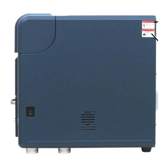
3.2 Part Names 3.2.1 Main Unit Figures 3.2.1-1, 3.2.1-2 and 3.2.1-3 show the front, back and right side of the main unit respectively. Top cover SYSTEM LED (Green) Turns ON when the system is normal. (Does not light when the error occurs.) AIR LED (Yellow) Turns ON when the... - Page 111 Power switch Figure 3.2.1-3 Main Unit (Right Side View) Figure 3.2.1-4 shows the electron gun section (under the top cover). Electron gun Electron gun cushion Axis adjustment knobs Figure 3.2.1-4 Electron Gun Section 3 - 3...
-
Page 112: Diaphragm Pump
3.2.2 Diaphragm Pump Figure 3.2.2 shows the diaphragm pump. Evacuation tube connector Power Signal connector connector Figure 3.2.2 Diaphragm Pump 3 - 4... - Page 113 3.3 PC Figures 3.3-1 and 3.3-2 show the components of the notebook PC. Note that the location of the USB port may differ depending on the PC. LCD monitor Notebook PC (Main unit) Mouse Figure 3.3-1 PC (Front View) USB2.0 port Figure 3.3-2 PC (Back View) 3 - 5...
-
Page 114: Operations
4 OPERATIONS 4.1 Summary of Operations This section explains the basic operations and terminology necessary for the use of the system. 4.1.1 Operation Units The principal operations of the system involve the use of the mouse and the keyboard. 1. Operating the Mouse Executes processing and specifies settings. 1a. -
Page 115: Operation Windows
4.1.2 Operation Windows The section explains operation windows used to control the model TM3000 Tabletop Microscope. On the operation window, a button is provided for each function so that buttons can be switched and adjusted by clicking them. Menu bar... - Page 116 5. Image observation area Displays the image being observed. 6. Information/comment area Upper row: Provides a data display of the image being observed. Lower row: Displays comments on the observation image. 7. Observation conditions settings button Specifies observation conditions. 8. Observation magnification settings button Specifies an observation magnification rate.
-
Page 117: Basic Operations
4.2 Basic Operations The flowchart below depicts the flow of basic operations. Details on the items that make up the flowchart are provided in each subsection and in Section 4.3, Detailed Description of Functions. 4.2.1 Starting the System 4.2.16 Terminating the Image Observation 4.2.17 Shutting Down the System 4.2.2 Fixing a Specimen and Adjusting its Height 4.2.3 Changing Specimens... - Page 118 4.2.1 Starting the System 1. Verify that the earth leakage breaker located on the back of the system is turned on. Figure 4.2.1-1 Earth Leakage Breaker 2. Turn on the Power switch located on the right side of the system. Figure 4.2.1-2 Starting the System (Pressing the Power Switch) 3.
- Page 119 AIR LED (yellow) Figure 4.2.1-3 AIR LED (Yellow) Solidly Lit 3c. EVAC LED (blue) solidly lit: Vacuum status (observation enabled) 3d. EVAC LED (blue) blinking: Evacuation in progress from atmospheric to vacuum status EVAC LED (Blue) Figure 4.2.1-4 AIR LED (Blue) Solidly Lit 4.
- Page 120 6. Turn on the PC. 7. Launch the application. 7a. On Desktop, double-click the [TM3000] shortcut icon Or, from the menu select [TM3000] or right-click the shortcut icon to select [Open]. Double-click or right click to select [Open] Select Figure 4.2.1-6 Launching the Application 7b.
- Page 121 NOTE : Verify that the main unit is connected to the PC with a USB cable. The application will not start if the USB cable is not connected. Also, the application will not start if the Power switch on the main unit is turned off. 4.2.2 Fixing a Specimen and Adjusting its Height 1.
- Page 122 2. The figure below shows an external view of a specimen stub (one set). Specimen stub Height adjustment screw lock nut 1 lock nut 2 Figure 4.2.2-1 External View of the Specimen Stub NOTE : When handling the specimen stub, wear clean gloves to keep the specimen stub free from particles and contaminants.
- Page 123 4. Affix the observation specimen on the conducting double-sided tape. Figure 4.2.2-3 Affixing the Observation Specimen on the Specimen Stub 5. Attach the specimen stub to a height-adjustment screw. Figure 4.2.2-4 Attaching the Specimen Stub to a Height Adjustment Screw 6.
- Page 124 7. As shown in Figure 4.2.2-5, adjust the height so that the gap between the specimen height gauge and the topmost surface of the specimen will be approximately 1 mm (0.5 to 1.5 mm). As shown in Figure 4.2.2-6, loosen the lock nut 1, adjust the height by turning the height adjustment screw, and then tighten the lock nut 1onto the lock nut 2 to secure the specimen stub.
-
Page 125: Changing Specimens
4.2.3 Changing Specimens 1. In the Midst of Observing a Specimen During the observation of a specimen, click the stop button on the Operation Window to terminate the observation process. Press the EVAC/AIR switch; wait for 3 minutes until the specimen chamber reaches the atmospheric pressure. - Page 126 Specimen stub Stage Figure 4.2.3-3 Taking Out the Specimen Stub Assembly 5. Insert the specimen stub assembly, with its height already adjusted, securely into the holder base for the stage until it stops. Lock nut 2 can be fixed with the hexagon socket head screw outside of the holder base. Tighten the hexagon socket head screw with the ball wrench 2 when observing at high magnification or observing the heavy specimen.
- Page 127 Hexagon socket head Specimen stub assembly screw Ball wrench 2 Stage feeding screw Head Figure 4.2.3-6 Hexagon Socket Screw for Fixing the Specimen Stub NOTE : Specimen stub assembly can be fixed with the hexagon socket head screw outside of the holder base. The vibration trouble might occur when observing at high magnification or observing the heavy specimen.
- Page 128 6. Align the specimen with the center of the specimen stage. Turn the stage knobs X and Y to align the tip of the positioning guide with the center position mark (a cross mark) shown in Figure 4.2.3-7. A: Center mark ●...
- Page 129 NOTE : As shown in Figure 4.2.3-9 Specimen Change (Readjustment), if the specimen or the specimen stub touches the upper face of the frontage, re-adjust the height of the specimen stub with reference to 4.2.2 6., 7. so that the specimen does not touch the front of the specimen chamber.
- Page 130 9. The evacuation-in-progress status is also indicated as a dialog in the application operation window (the dialog disappears upon completion of the evacuation). Dialog Figure 4.2.3-11 Evacuation-in-progress Screen 4 - 17...
-
Page 131: Starting Observing An Image
4.2.4 Starting Observing an Image 1. When the EVAC/LED (blue) on the main unit lights up solidly, the Start button on the operation window is enabled for clicking. Click Figure 4.2.4-1 Starting Observing an Image 2. Either click the Start button on the operation window or on the menu operation unit click File Menu →... -
Page 132: Selecting A Display Mode
4.2.5 Selecting a Display Mode Change the display mode for the image observation area to the Fast mode and find the target observation FOV. In the next step, set the Reduce mode to adjust the brightness and the focus. A display mode can be set by using the following methods: 1. - Page 133 1c. Reduce Mode This is a display mode well-suited for the adjustment of the brightness or focus of the image being observed. Figure 4.2.5-4 Display Mode Buttons (Image Adjustment) 1d. Freeze Mode This display mode allows the user to hold the image being observed still.
-
Page 134: Setting An Observation Mode
4.2.6 Setting an Observation Mode Select an observation mode from the Observation mode on the Settings menu. Figure 4.2.6 Setting an Observation Mode (Standard Mode) In the observation mode in Figure 4.2.6, Setting an observation mode, the standard mode is check-marked. -
Page 135: Setting An Observation Condition
4.2.7 Setting an Observation Condition Select an observation condition either by operating the observation condition buttons in the observation condition setup unit or from the View menu. On the observation condition button, the part enclosed in a green frame represents the currently selected observation condition (when the system is started, the previous observation condition is displayed). - Page 136 2. Auto Operation The Auto B/C mode automatically adjusts the brightness and contrast. Figure 4.2.8-2 Adjusting the Brightness/Contrast of an Image (Auto B/C Operation) Either clicking the Auto B/C button or selecting the Auto brightness/contrast adjustment option on the view menu executes the automatic adjustment of brightness and contrast. Figure 4.2.8-3 Image Brightness/Contrast Adjustment (Auto B/C Execution Screen) Changing the FOV or the magnification on the specimen being observed can vary the brightness and contrast of the image.
-
Page 137: Coarse Adjustment Of The Focus
4.2.9 Coarse Adjustment of the Focus Focusing can be adjusted by using both auto and manual modes. 1. Manual Operation Figure 4.2.9-1 Coarse Adjustment of Focusing (Manual Operation) The focus changes when the + or – side on the button is clicked. Clicking continuously causes the focus to vary continuously. -
Page 138: Selecting An Observation Fov
Either click the auto-focus button or select Auto Focus on the View menu to execute auto focusing. Figure 4.2.9-4 Coarse Focusing (Auto-focusing in Progress Screen) The precision of auto-focusing can be affected by the surface structure of the specimen. Auto-focusing will not operate properly if the specimen surface contains few minute structural features, its contrast is low, or the specimen is liable to become charged. - Page 139 NOTE : If the rotation is not 0°, the direction in which the image moves vary. Therefore, first set the rotation to 0°, move the FOV, and then use the rotation to rotate the image. (2) Manual Stage To move the FOV extensively, adjust the mouse cursor to △ mark on the observation screen and hold the left mouse button down.
- Page 140 Turning the Y knob (on the right side when viewed from the front) on the manual stage to the right (clockwise) moves the observation image to downward; turning it to the left (counterclockwise) moves the observation image upward. Y knob Figure 4.2.10-2 Selecting an Observation FOV (Y-Knob) 2.
- Page 141 2b. Click Center Function The double-clicked position moves to the center of the observation screen by the motor drive or the image shift function when double-clicking left mouse button when the mouse cursor is on the observation screen. Either the motor drive or the image shift is automatically decided by the amount of the movement and the observation magnification.
- Page 142 The double-clicked position moves to the center of the observation screen. 4. Resetting the Image Shift Figure 4.2.10-6 Selecting an Observation FOV (Image Shift Reset Operation) Clicking the image shift reset button returns the FOV to the position that was in effect before image shifting was performed.
-
Page 143: Setting An Image Mode
4.2.11 Setting an Image Mode Image observation can be conducted in any of three image modes: COMPO, shadow, and TOPO. Figure 4.2.11 Setting an Image Mode (Changing Image Modes) For details, see 4.3.12 Image Mode Button. 4.2.12 Setting a Magnification A magnification can be set by any of the following methods: 1. - Page 144 FOV deviation can occur. In such a case, change magnifications by using the observation magnification button. Hitachi recommends that the Preset button is used at x5,000 or less.
- Page 145 Select a magnification from magnification specifications values on the View menu. The current magnification changes to the selected magnification. Figure 4.2.12-4 Setting a Magnification (View Menu Operation) Change the magnification in order to adjust the observation position for the specimen. Although the specific magnification to be used depends on the size of the specimen, a magnification of 100x or less is generally suitable for adjusting the specimen position.
-
Page 146: Fine Focusing
4b. Pressing the left button on the mouse and dragging it to the right and left changes the magnification. Dragging it to the right increases the magnification, and dragging it to the left decreases it. While viewing the image, perform adjustments until an appropriate magnification level is attained. - Page 147 1c. While pressing the left button on the mouse, drag it to the right and left for fine-focusing. While viewing the image, perform adjustment until an appropriate focusing level is attained. Figure 4.2.13-3 Fine Focusing (Mouse-Dragging) 2. Mouse-Dragging within the Focusing Button See Section 4.3.21 Focus Button. Fine focusing, however, is not enabled if the accelerating voltage is off or the View mode is in the freeze image mode.
- Page 148 In the presence of astigmatism, moving the focus back and forth (see 4.2.13 1. 2. ) produces an image that runs in one direction, as shown below: Figure 4.2.13-5 Astigmatism Correction Screen (2) If astigmatism is present, the problem can be corrected as described below. For ease of correction, astigmatism correction and focusing correction might be performed in alternating fashion.
-
Page 149: Saving The Image Data
3b. Using focusing adjustment, set the focus in the condition shown in Figure 4.2.13-5 (A). Position (A) is the middle position of the points through which the image runs vertically. 3c. By dragging the slider bars for astigmatism correction 1 and astigmatism correction 2, make the image more clearly visible. - Page 150 1b. A Setting for Save window appears. On this window, specify information view/hide settings, edit any comment entry, and select the type of image save to be performed. Figure 4.2.14-2 Setting for Save Window Table 4.2.14-1 Image Save Type and Image Save Size (.jpg) Image Save Type Quick Save (size) Save (size)
-
Page 151: Checking The Image Data
1c. Click the [SET] button to commit the settings. After committing the settings by clicking the [OK] button, close the Setting for Save window. 2. Standard Save For details, see 4.3.15 Save Button. 3. Quick Save For details, see 4.3.14 Quick Save Button. 4.2.15 Checking the Image Data Using Windows Explorer, display a list of saved images. -
Page 152: Terminating The Image Observation
4.2.16 Terminating the Image Observation 1. Click the [Stop] button to terminate the image observation process. Figure 4.2.16-1 Terminating the Image Observation (Stop Button) 2. When continuing to observe an image, perform the steps described beginning in Section 4.2.4 Starting Observing an Image. When observing another image, perform the steps described beginning in Section 4.2.2 Fixing a Specimen and Adjusting its Height. -
Page 153: Shutting Down The System
4.2.17 Shutting Down the System 1. When stopping to observe other specimens on a continuing basis, press the EVAC/AIR switch to set the specimen chamber to the atmospheric pressure, and remove the specimen that had been loaded. 2. Press the EVAC/AIR switch to set the specimen chamber to a vacuum (observation-enabled) status. - Page 154 4. Turn off the Power switch on the main unit to shut it off. Figure 4.2.17-3 Shutting Down the System (Pressing the Power Switch) NOTICE : If image observation is not performed for a long time, in order to keep the specimen chamber in a vacuum condition, activate the main unit at least once every two weeks, set it in a vacuum state (observation-enabled condition) (with the EVAC indicator (blue) lit up solidly), and then shut down the system.
-
Page 155: Detailed Description Of Functions
4.3 Detailed Description of Functions 4.3.1 Image Viewing Area The image viewing area displays the observation image. System operations are performed by viewing the observation image displayed in this area. By dragging the mouse by pressing the left button on the mouse on the image viewing area (see 4.2.13 3. -
Page 156: File Menu
NOTE : The scaling cannot be set in the hide mode. The observation mode (see Section 4.3.6 5. ) is display when the charge-up reduction mode is selected in an observation-enabled status (when the specimen chamber is in a vacuum state). The Image mode (see Section 4.3.5 2. - Page 157 2. Saving Image Figure 4.3.3-3 File Menu (Image Save Menu) 2a. Quick save Depending on the particular View mode that is selected, this button captures the image being observed and saves it as an image file (image save size: 640x480 pixels (image only), 640x520 pixels (image + information), and 640x550 pixels (image + information + comments)).
-
Page 158: Edit Menu
4.3.4 Edit Menu Figure 4.3.4 Edit Menu 1. Copy Image Copies the image being observed to the clipboard. This button is enabled when the View mode is the freeze mode. The image size produced by the image copying process is 640x480 pixels for a freeze image, 1280x960 pixels for a freeze image after the execution of save, and 1280x960 pixels for a freeze image after the execution of the Digital Zoom screen. -
Page 159: View Menu
4.3.5 View Menu Figure 4.3.5-1 View Menu 1. View Mode Figure 4.3.5-2 View Menu (View Mode Menu) For details, see 4.3.11 View Mode Selection Button. 2. Image Mode Figure 4.3.5-3 View Menu (Image Mode Menu) For details, see 4.3.12 Image Mode Button. 3. - Page 160 Selecting either of the two magnifications that were set on the Preset Magnification screen causes the direct switching to that magnification. The same operation can be performed by using the Preset Magnification button. 4. Magnification Figure 4.3.5-5 View Menu (Magnification Menu) A change is made to the magnification selected on the menu.
-
Page 161: Setting Menu
4.3.6 Setting Menu Figure 4.3.6-1 Setting Menu 1. Auto B/C Adjustment… This function displays the Auto B/C Adjustment window that presets conditions (brightness and contrast levels) for Auto B/C adjustment. 2. Preset Magnification… This function displays the Preset Magnification Settings screen that sets a preset magnification in advance. - Page 162 5. Observation Mode 5a. Standard Mode Figure 4.3.6-3 Settings Menu (Observation Mode Menu) Ordinary specimens, such as industrial materials, should be observed in standard mode. This function changes the vacuum level of the specimen chamber to a relatively high vacuum level.
-
Page 163: Stage Menu
4.3.7 Stage Menu The following menus are displayed when the motor drive stage is installed. Figure 4.3.7-1 Stage Menu 1. Stage Position Displays the stage position display window to show the stage position on a present observation screen. Specimen position monitor Specimen stub image Present observation position Specimen stub size... - Page 164 1e. Home position button Moves the motor drive stage to home position. NOTE : In the following cases, the following dialog is displayed until the initialization processing is completed. At this time, the operation screen cannot be operated. ・ When the initialization of the stage position (starting point movement) isn't completed while the application program is starting ・...
- Page 165 2b. 4 Points Display the stage operation button in four directions. (top/bottom/right/left) Figure 4.3.7-5 Mouse Control Mode 2 2c. None Hides the stage move button. Figure 4.3.7-6 Mouse Control Mode 3 NOTE : While introducing the air into the specimen chamber, the stage cannot move. 4 - 52...
-
Page 166: Maintenance Menu
4.3.8 Maintenance Menu Figure 4.3.8 Maintenance Menu 1. Beam Axis Alignment … This function displays the Beam Axis Alignment window that allows the user to perform optical axis alignment on the electron beam. Use this window if beam axis conditions changed after filament change, maintenance operations, or a change in observation conditions. -
Page 167: Help Menu
4.3.9 Help Menu 4.3.9-1 Help Menu 1. Instruction Manual … F1 Displays the instruction manual of the TM3000 main unit. 2. Explanation of Buttons Figure 4.3.9-2 Help Menu (Explanation of Buttons Menu) 2a. Show Changes settings so that an explanation is displayed when the mouse cursor is moved to under the button which is the principal operation unit on the operation window. -
Page 168: Start/Stop Button
4.3.10 Start/Stop Button 1. Start (HV-ON) Button Figure 4.3.10-1 Start/Stop Button (Start) [Start] means that electron beam irradiation is off (HV-OFF). Clicking the [Start] button turns on the power source for the electron gun in order to irradiate the specimen with the electron beam, and the process of heating by the filament commences, a process that requires approximately 10 seconds. - Page 169 Figure 4.3.10-3 Auto Start Execution Window NOTE : The Start button is not enabled until the specimen chamber becomes stable in an observation-enabled vacuum state. Normally, the Start button becomes operable after specimens are changed, the EVAC/AIR switch on the front side of the system main unit is pressed, and three minutes have elapsed.
-
Page 170: View Mode Selection Button
4.3.11 View Mode Selection Button This button changes view modes. The current view mode button is indicated by a solidly lit yellow button. Change to the view mode of your choice while viewing the image. The following view modes are available: 1. -
Page 171: Image Mode Button
This is a view mode that renders the current image into a freeze image. NOTE : Compared with the Slow mode, the Fast mode degrades image quality. NOTE : To prevent damage to the specimen by the electron beam, if approximately 5 minutes elapses with electron beam irradiation on (HV-ON) and with Freeze selected in the View mode, the observation operation is canceled (HV-OFF), and a message is displayed. - Page 172 1. COMPO Sets the observation image to the COMPO condition. This is a mode in which the system is turned on. Figure 4.3.12-3 Setting an Image Mode (COMPO Mode) 2. Shadow 1 Sets the observation image to a shadow image (an image illuminated from the above).
- Page 173 4. TOPO Sets the observation image to the topo display. This method is useful when the topographic information is to be exaggerated during the observation. When TOPO is selected, the information area in the lower right part of the observation screen is indicated by a [T] mark (see 4.3.2).
-
Page 174: Observation Condition Selection Button
4.3.13 Observation Condition Selection Button Figure 4.3.13-1 Observation Condition Selection Button Select an observation mode from the observation mode in the observation condition settings unit. Change observation modes to match the sample on hand and the prevailing observation condition. For the various observation conditions, see the explanations provided below. 1. - Page 175 This observation, well-suited for observing specimens that do not produce adequate brightness/contrast levels, yields smooth images. 4. Setting an Observation Condition from the View Menu On the View menu, select one of the following observation conditions: 5 kV, 15 kV, and Analy. Figure 4.3.13-5 Setting an Observation Condition (15 kV Mode) In Figure 4.3.13-5, the 15 kV observation condition is check-marked.
-
Page 176: Quick Save Button
4.3.14 Quick Save Button Figure 4.3.14-1 Quick Save Button This button saves the currently displayed image as is. Image save size: 640x480 pixels (image only), 640x520 pixels (image + information), 640x550 pixels (image + information + comments) Image save format: JPEG (*.jpg), bitmap (*.bmp), TIFF (*.tif) 1. - Page 177 When the image pauses, a dialog appears in the center of the window. When a freeze image is set, the dialog disappears. When canceling a Quick Save operation, click the [Cancel] button on the dialog. NOTE : If Quick Save is executed in the View mode from either Fast or Reduce, the Quick Save operation cannot be canceled.
-
Page 178: Save Button
4.3.15 Save Button Figure 4.3.15-1 Save Button This button saves high-definition images. Image Save size: 1280x960 pixels (image only), 1280x1040 pixels (image + information), 1280x1100 pixels (image + information + comments) Image save format: JPEG (*.jpg), bitmap (*.bmp), TIFF (*.tif) 1. - Page 179 During image capture, a dialog appears in the center of the window, indicating the progress of the image capture process. The dialog disappears when image capture is finished. To cancel saving the image, click the [Cancel] button on the dialog. NOTE : To avoid noise in the saved image, be careful not to exert any vibration on the system main unit during the image capture process.
-
Page 180: Magnification Button
4.3.16 Magnification Button Figure 4.3.16-1 Magnification Button This button allows the user to change the observation magnification. To increase the magnification from the current level, click the + side; to decrease it, click the – side. These operations change the current magnification to a level one step above or below the current level, and the image changes to the new magnification rate. -
Page 181: Preset Buttons
4.3.17 Preset Buttons Figure 4.3.17 Preset Buttons Clicking the Preset button changes the current magnification to the magnification that is display on the button. Set two preset magnifications to one that facilitates finding an observation position and one to be used when saving the image. In this manner, switching to an intended magnification can be accomplished simply by clicking the Preset button. - Page 182 1. Adjusting the brightness Figure 4.3.18-2 Adjusting the Brightness of the Image (Manual Operation) Brightness (+) Contrast (+) Contrast (-) Brightness (-) Figure 4.3.18-3 Adjusting the Brightness of the Image 2. Adjusting the Brightness (Mouse-Dragging) 2a. Moving the mouse cursor into the Brightness button changes the appearance of the cursor to a brightness adjustment display Figure 4.3.18-4 Adjusting the Brightness of the Image (Mouse-Dragging) 4 - 69...
-
Page 183: Contrast Button
2b. Adjust the brightness by pressing the left button on the mouse and dragging it to the right and left. Dragging to the right on the Brightness button increases the brightness; dragging it to the left decreases it. While viewing the image, perform adjustments until an appropriate brightness is attained. - Page 184 2. Contrast Adjustment (Mouse-Dragging) 2a. Moving the mouse cursor into the contrast adjustment button causes the cursor display to change to the contrast adjustment view Figure 4.3.19-3 Mouse-Dragging (Dragging Operation) 2b. Perform adjustment by pressing the left button on the mouse and dragging it to the right and left.
-
Page 185: Auto B/C Button
4.3.20 Auto B/C Button Figure 4.3.20-1 Auto B/C Button This button automatically adjusts the brightness and contrast of the image being observed. Clicking the Auto B/C button starts the auto brightness/contrast adjustment process. A dialog appears while the processing is in progress. The dialog disappears when the processing is finished. -
Page 186: Focus Button
4.3.21 Focus Button Figure 4.3.21-1 Focus Button Adjust the focusing in the height direction of the specimen. To reduce the focal distance (the specimen is too high) from the current adjustment, click the + side. On the other hand, to increase the focal distance (the specimen is too low), click the –... -
Page 187: Auto Focus Button
3. Perform focus fine adjustment by pressing the left button on the mouse and dragging it to the right and left. While viewing the image, perform adjustment for an appropriate focusing. If the cursor moves outside the focus button range, adjustment can still be effected until the left button is released. -
Page 188: Image Shift Reset Button
4.3.23 Image Shift Reset Button Figure 4.3.23 Image Shift Reset Button Clicking the Image Shift Reset button resets the FOV to the condition that existed before the Image Shift (see 4.2.10 2.) was performed. NOTE : Because the range over which the FOV can be moved by image shifting is limited (see Section 1.3), if the FOV ceases to move, press the Reset button once, move the FOV by manipulating the XY knobs, and then use the Image Shift again for fine adjustments. -
Page 189: Edit Button
5. Fine-Adjusting the Rotational Position Clicking the + mark rotates the image clockwise; the – mark rotates it counterclockwise. Clicking it continuously produces continuous change one step at a time. Image turns to (-) Image turns to (+) Figure 4.3.24-2 Selecting an Observation FOV (Rotation Operation) NOTE : If the rotation position is not 0°... - Page 190 1. [Image View] Tab This tab allows the user to edit the contents of the Information/Comments area, and specify Show/Hide. Observation magnification Image number Date Time Comment Distance Figure 4.3.25-2 Save Settings Area 1a. Information Figure 4.3.25-3 Information Block (1) Date Specifies show/hide for the date in the information field. Placing a checkmark on the date imprints the date of capture on the saved image (Save Image type: other than Image Only).
- Page 191 (4) Magnification NOTE : The magnification shown in the information area is indicated in an [xMMM] format. A magnification greater than 1000 is represented by xM.Mk, and a value greater than 10000 by xMMk. This screen sets the Show/Hide of the magnification in the information field. Placing a checkmark on Observation Magnification imprints the magnification used during the image capture on the saved image (Save Image type: other than Image Only).
- Page 192 2. [Image Save] Tab 2a. Image Type Figure 4.3.25-5 Image Type Block By selecting the image save type, the user can enter the type of auxiliary information display for the saved image and the file name. Table 4.3.25 Image Save Type and Image Save size Image Type Quick Save Save...
- Page 193 (1) Image only ・ Information/comments area The characters in the information and comments areas are hidden. Figure 4.3.25-6 Information/Comments Area (Characters Hidden) ・ Save Image The saved images are an image file consisting exclusively of observation images (Save Image size: standard save: 1280x1024 pixels, Quick Save: 640x480 pixels). Figure 4.3.25-7 Save Settings Screen (Characters Hidden) (2) Image + information ・...
- Page 194 Figure 4.3.25-9 Save Settings Screen (Comments Area Characters: Hidden) (3) Image + information + comments ・ Information/Comments area Displays characters in the Information/Comments areas. Figure 4.3.25-10 Information/Comments Area (Information/Comments Area Characters: Displayed) ・ Saved Image The saved image is an image file in which information and comments (items that are applied using the [Screen Display] tab) are entered in the observed image (Save Image size: Standard Save: 1280x1100 pixels, Quick Save: 640x550 pixels).
- Page 195 NOTE : The magnification embedded in the saved image is a magnification based on the observation image display on the observation screen. NOTE : If the observation mode [L] mark (see 4.3.6 5.) or the image mode [S] [D] [T] mark (see 4.3.5 2.) is displayed in the information area, similarly those marks are also embedded in the saved image.
-
Page 196: Minimize Button
Minimizes the application program. The minimized application program is stored in [Hitachi TM3000] on the Taskbar. Figure 4.3.26-2 Taskbar To deminimize, click [Hitachi TM3000] on the Taskbar. This displays the application program. 4.3.27 Exit Button Figure 4.3.27-1 Exit Button Terminates the application program. Clicking [OK] on the Application Termination Confirmation screen terminates the application program. -
Page 197: Setting For Save Window
4.3.28 Setting for Save Window Figure 4.3.28 Setting for Save Window For details on settings, see 4.3.25 Edit Button. 4 - 84... -
Page 198: Save Image Window
4.3.29 Save Image Window Figure 4.3.29 Save Image Window This window allows the user to save an image file by specifying a destination and a file name. 1. Location of Save Upon termination of the capture of the observation screen using [Save] and [Quick Save], a list of available drives and folders is displayed. - Page 199 3. File Type Three image file types are supported: Table 4.3.29 File Types File Type Format JPEG file (*.jpg) JPEG compatible image file (images saved by compression) Bitmap file (*.bmp) Bitmap image file (images saved without compression) TIFF file (*.tif) Tagged image file format (images saved without compression) ※...
-
Page 200: Digital Zoom Window
4.3.30 Digital Zoom Window Figure 4.3.30-1 Digital Zoom Window Digital zooming operation can be performed for the observation image. Zoom magnification: Select a digital zoom magnification (x2 or x4) from the box. Zooming location specification frame: Using a frame, specify the location where digital zooming is to be performed. - Page 201 Save button: This button performs a Quick Save in the condition of the displayed image (Image Save size: 640x480 pixels) on the Digital Zoom window. Close button: Closes the Digital Zoom window. Digital Zoom operation 1. Selecting digital zoom on the Edit menu starts the capturing of high-definition images (image capture), irrespective of the current View mode.
- Page 202 2. Upon termination of the image capture process, the dialog disappears, and the Digital Zoom screen is displayed. Figure 4.3.30-3 Digital Zoom Window 3. Clicking [Zoom] by specifying a zoom magnification and a zoom location displays a digital zoom image. Figure 4.3.30-4 Digital Zoom Execution Window 4 - 89...
- Page 203 4. Click [Save] to save the digital zoom image. As a Save Image window appears, enter the file name, and save the image by selecting the destination of save and the file type. If not saving the image, click the [Cancel] button. NOTE : Any of the following characters cannot be used in a file name: [\ / : ;...
-
Page 204: Data Entry/Measurement Window
NOTE : If a magnification is embedded in the information area and the saving of a digital zoom image is executed, the magnification is also embedded in the saved image. The embedded magnification will be the virtual magnification [D x MMM] used during the execution of digital zooming. - Page 205 Figure 4.3.31-2 Choosing the Data Entry/Measurement from a Pull-Down Menu Figure 4.3.31-3 Image Capture Execution Window 1b. The Data Entry/Measurement window is displayed. Figure 4.3.31-4 Data Entry/Measurement Window 4 - 92...
- Page 206 1c. From the entry mode selection button, select the data to be entered (characters and graphics) to enter data. Figure 4.3.31-5 Data Entry/Measurement Window NOTE : Entered data (characters and graphics), once it is saved, cannot be re-edited. To change data, before it is saved, delete it by pressing the Clear button and re-enter it.
- Page 207 2. Entry Mode Selection Buttons The following data entry modes are available for selection: Entry cancellation button: Cancels the input of data. Character entry button: Allows the input of characters. Left-clicking any location on the screen where text is to be inserted, the text insertion part is displayed black-on-white. From the keyboard, enter text, and press the ENTER key to commit it.
- Page 208 Circle button: Draws a circle. Left-click the mouse at the starting point of the circle, move the mouse while holding down on the button, and release the button to draw the circle. Square button: Draws a square. Left-click the mouse at the starting point of the square, move the mouse while holding down on the button, and release the button to draw the square.
-
Page 209: Image Balance Window
4.3.32 Image Balance Window Figure 4.3.32 Image Balance Window This window allows the user to adjust the image on the Data Entry window. Brightness slider: Adjusts the brightness. Dragging the slider to the right increases the brightness; dragging it to the left decreases it. Contrast slider: Adjusts the contrast. -
Page 210: Preset Magnification Window
FOV deviation can occur. In such a case, change magnifications by using the observation magnification button. Hitachi recommends that the Preset button be used at x5,000 or less. -
Page 211: Control Sensitivity Window
This button allows the user to set a brightness or contrast level for auto brightness/contrast adjustment. Selecting Auto B/C Adjustment Settings on the Settings menu displays the Auto B/C Adjustment window. On this window, set the brightness and contrast levels to desired levels. -
Page 212: Beam Axis Alignment Window
3. Contrast With respect to the Contrast button on the operation window, specifies the sensitivity of operation (the speed of continuous contrast change) when the button is clicked continuously. 4. Focus With respect to the Focus button on the operation window, specifies the sensitivity of operation (the speed of continuous focus change) when the button is clicked continuously. - Page 213 menu activates the Beam Axis Alignment window. Before performing a beam axis alignment, set the supplied image verification specimen on the specimen stage. For details, see Section 5.2 Beam Axis Alignment Methods. NOTE : The Beam Axis Alignment window appears only when electron beam irradiation is on (HV-ON).
-
Page 214: Observation Screen Size Window
Stop button: Cancels the beam axis alignment process and closes the Beam Axis Alignment window. 4.3.37 Observation Screen Size Window Figure 4.3.37 Observation Screen Size Window Displays an observation screen size window for registering the size of the image observation area (see 2.2.7). An observation screen size must be set after an application is installed. -
Page 215: Astigmatism Correction
4.3.38 Astigmatism Correction Figure 4.3.38 Astigmatism Correction An astigmatism correction (to correct any electron beam distortion) on the observation screen can be performed here. Perform this adjustment if focusing becomes difficult to adjust due to aging or after the column is serviced, including filament replacement. An astigmatism correction operation unit can be displayed in the information/comments area on the operation window by selecting astigmatism correction on the settings menu. -
Page 216: User Information Window
4.3.39 User Information Window Figure 4.3.39 User Information Window On this window, user information for the management of applications can be recorded. Use this window if the party responsible for controlling this program for operational purposes must be tracked. On the Help menu, selecting user information displays the user information window. -
Page 217: Version Information Window
4.3.40 Version Information Window Figure 4.3.40 Version Information Window The Version Information window displays the product logo, the software version, and copyright declarations. The lower part of the window shows the information that was registered on the user information window. Selecting version information on the Help menu displays a version information window. -
Page 218: Maintenance
5 MAINTENANCE Periodically perform inspection and maintenance of the following items to keep the system in good working condition to extend the lifetime of the instrument. 1. After reading this instruction manual carefully, perform the maintenance according to the procedures described in this manual. 2. -
Page 219: Filament Replacement
5.1 Filament Replacement If an image does not appear when an application button is pressed or a filament-related error message appears, a blown filament must be suspected. Any blown filament, which provides a light source that permits observation, must be replaced. 1. - Page 220 4. When the blue LED lights up, it is an indication that the specimen chamber has reached the atmospheric pressure, in which case turn off the power switch. 5. There is a rubber cushion on the left side of the electron gun. Tilt the electron gun to the left side of the system until it touches the cushion, and then gradually open the electron gun.
- Page 221 NOTE : When handling the components inside the electron gun (the cap, the Wehnelt, the anode, and the cartridge filament), use clean gloves to keep them free of particles and smudges. Wehnelt and Cartridge filament Figure 5.1-6 Removing the Welnelt Figure 5.1-7 and the Cartridge Filament Welnelt and Cartridge Filament...
- Page 222 Location to be cleaned Figure 5.1-10 Cleaning the Wehnelt 1 Dissolve the supplied metal polishing agent in alcohol, apply it to the tip of a cotton swab, and clean the spots shown in Figure 5.1-10. Finally, thoroughly wipe the cleaned spots with alcohol to remove any residual metal polishing agent or particles, and remove lint and particles with an air blower.
- Page 223 Location to be cleaned Figure 5.1-13 Cleaning the Anode 1 Figure 5.1-14 Cleaning the Anode 2 10. Fasten the Wehnelt onto the new cartridge filament. The tip of the filament is like an extremely thin wire. Touching it ever slightly can deform it, rendering it unusable.
- Page 224 Spacer is used to adjust the image brightness. Reuse (Wehnelt) If broken: Cartridge Discard filament (Cartridge filament, spacer) Figure 5.1-16 Replacing the Cartridge Filament Spacer Fasten the Wehnelt onto the cartridge filament clockwise. Incorporate it into the electron gun by verifying it that there is not play. Align the guard ring pin with the holder groove of the cartridge filament, and insert it vertically.
- Page 225 11. Attaching the cap Secure the cap, by turning it clockwise, onto the cartridge filament that was attached in Section 5.1 10. . Figure 5.1-20 Cap Figure 5.1-21 Attaching the Cap 12. Verify that grease is applied to the o-ring and is free of particles, then attach the o-ring to the groove.
- Page 226 13. Press the [EVAC/AIR] switch. The filament replacement process is complete when the evacuation is finished. In the next step, perform beam axis adjustments (see Section 5.2). Figure 5.1-23 Filament Replacement Finished 5 - 9...
-
Page 227: Beam Axis Adjustment
5.2 Beam Axis Adjustment 1. Press the [EVAC/AIR] switch. Verify that the evacuation of the specimen chamber is finished. After replacing the filament (see Section 5.1), set the supplied standard specimen (see Sections 4.2.2 and 4.2.3) in the center of the stage, press the [EVAC/AIR] switch, and verify that the evacuation of the specimen chamber is finished. - Page 228 3. Start the beam axis adjustment mode. Beam axis adjustment is a three-step process, involving a gradual adjustment of the beam irradiation position to the center of the lens. From the [Maintenance] menu, select [Beam axis adjustment] to bring up the Beam Axis Adjustment window. Figure 5.2-3 Starting the Beam Axis Adjustment Mode NOTE : Beam axis adjustment can be performed only when electron beam irradiation is on (with HV-ON).
- Page 229 Specify electron beam conditions. Figure 5.2-5 Electron Beam Condition Setup Window (1) ※ If the supplied image verification specimen is not loaded, in the confirmation message shown in Figure 5.2-4, click the [Cancel] button. When the following message appears, click the [OK] button, and by following the message, load the supplied image verification specimen and perform the beam axis adjustment procedure again.
- Page 230 Figure 5.2-7 Beam Axis Adjustment STEP 1, an Example 4a. First, loosen the four axis adjustment knobs, A, B, C and D, by approximately one turn. Figure 5.2-8 Operating the Electron Gun Axis Adjustment Knobs (1) Figure 5.2-9 Operating the Electron Gun Axis Adjustment Knobs (2) 4b.
- Page 231 4c. When the image on the observation screen turns into an image as shown in Figure 5.2-10, click the [STEP 2] tab. Figure 5.2-10 STEP 1 Reference Image NOTE : Figure 5.2-10 is only an example. Don’t be alarmed if the same image does not appear;...
- Page 232 5. Beam Axis Adjustment STEP 2 Turn the four axis adjustment knobs, A, B, C, and D, for the electron gun to move the electron gun, and adjust it so that the window will be the brightest. Figure 5.2-12 Beam Axial Adjustment STEP 2 5a.
- Page 233 NOTE : Figure 5.2-13 is only an example. Don’t be alarmed if the same image does not appear; it is not a problem. 6. Beam Axial Adjustment STEP 3 (if STEP 2 was Not Successful) Turn the four axis adjustment knobs, A, B, C, and D, for the electron gun to move the electron gun, and adjust it so that the image will be the brightest.
- Page 234 NOTE : Figure 5.2-15 is only an example. Don’t be alarmed if the same image does not appear; it is not a problem. 7. The END of Beam Axis Adjustment Set the electron beam irradiation conditions in the observation conditions. Upon completion of the setting step, the beam axis adjustment window disappears, marking the conclusion of the process.
- Page 235 9. Checking Performance After replacing the filament, check image quality by using the supplied image verification specimen. Use the same method if image deterioration becomes apparent after the system is used. 9a. Set the supplied image verification specimen in the standard position. See Section 4.2.3 Changing Specimens.
-
Page 236: Condenser Lens Aperture Replacement
5.3 Condenser lens Aperture Replacement The condenser lens aperture is built into the liner tube and it is located underneath the anode. After the system has been in use for about 6 months and it appears that there is image deterioration (an out-of-focus condition), replace the condenser lens aperture. - Page 237 NOTE : When handling the components inside the electron gun (the cap, the Wehnelt, the anode and the cartridge filament), use clean gloves to keep them free of particles and smudges. CAUTION : The electron gun weighs 2.5 kg. When opening the electron gun, do not release your hand until the electron gun comes to a halt.
- Page 238 Holder Pipe holder Condenser Top holder lens aperture Pipe 3 Pipe 1 Holder Pipe holder Pipe 2 Condenser Condenser Holder Holder lens aperture Condenser lens aperture lens aperture Figure 5.3-5 Disassembling the Liner Tube 8. When handling the condenser lens aperture, use caution since it is thin and easily to deform.
- Page 239 9. Place the top holder as shown in the photograph below. Drop down the aperture from the above into the center of the top holder. Use caution so that the aperture is not tilted. In the next step, mount the holder, and secure the pipe by tightening it onto the top holder screw thread.
-
Page 240: Objective Aperture Replacement
11. Insert the liner tube into the liner pipe. Mount the anode by turning it clockwise, and replace the electron gun to its original position. This concludes the condenser lens aperture replacement process. Liner Pipe Figure 5.3-11 Replacing the Condenser lens Aperture (4) 5.4 Objective Aperture Replacement The objective aperture is built into the liner tube. - Page 241 NOTE : When handling the components inside the electron gun (the cap, the Wehnelt, the anode, and the cartridge filament), use clean gloves to keep them free of particles and smudges. CAUTION : The electron gun weighs 2.5 kg. When opening the electron gun, do not release you hand until the electron gun comes to a halt.
- Page 242 Liner pipe Figure 5.4-4 Pulling the Liner Pipe Out (2) NOTE : Since the liner pipe is thin and easily bent, when pulling it out, pull it straight up. 6. Remove the objective aperture unit; replace the objective aperture unit. Grasp the center of the liner pipe, and using a slotted screwdriver, turn the stopper at the tip counterclockwise to take out the objective aperture unit.
- Page 243 Objective aperture O-ring Spacer Aperture holder Stopper Figure 5.4-7 Figure 5.4-8 Liner Pipe Objective Aperture Unit and Liner Pipe 8. Install the liner pipe. Insert the liner pipe into the hole from which it was pulled out, and with fingers push it all the way in.
-
Page 244: Error Messages
5.5 Error Messages 5.5.1 Messages That are Displayed When a Given Application is Started Listed below are principally error messages that are displayed after an application is started. <<Error Messages List>> Code Error Message Countermeasure 1000 Failed to access the memory. Click the [OK] button to close the program. - Page 245 Code Error Message Countermeasure 1081 No application files found, or Click the [OK] button to close the program. failed to access these files. If application files access error occurs, this Could not start up the message appears. When the account type into application.
-
Page 246: Initial Startup Window (During Initialization)
5.5.2 Initial Startup Window (During Initialization) Listed below are principally messages that are displayed when an application is being started (when the initial window is being displayed). <<Error Message List>> Code Error Message Countermeasure 1101 The data in Adjust File are Click the [OK] button to close the program. - Page 247 1160 Main Power Switch is off, or the The TM3000 main unit may be de-energized or USB cable is not connected. the USB cable may be disconnected. Restart the system in the following procedure.
-
Page 248: Normal Observation Screen
5.5.3 Normal Observation Screen Listed below are principally messages that are displayed when an error is found on the normal observation screen. <<Error Messages List>> Code Error Message Countermeasure 1201 Time has run out. The high This message appears if a time-out has occurred voltage cannot be applied. - Page 249 Code Error Message Countermeasure 1209 The electron gun or the high Abnormality on the high voltage power supply voltage power supply stopped has been detected. It is possible that an due to the failure. emission current greater than 200 μA (an Start up the main unit and overcurrent) was detected.
- Page 250 Code Error Message Countermeasure 1212 Beam current is too high. An emission current of 200 µA or more Please check the filament (overcurrent) has been detected during a setting. gradual-increase process of high voltage. Click the [OK] button to dismiss the message. Make sure there are no particles on the filament tip and Wehnelt opening.
- Page 251 Code Error Message Countermeasure 1223 Beam current is too low. An emission current level higher than 10 µA or Please check the filament lower than 20 µA has been detected while the setting. electron beam is being emitted. Click the [OK] button to dismiss the message.
- Page 252 Code Error Message Countermeasure 1242 Was the reference sample set in This message appears to confirm that the the center of the stage? furnished reference sample is set to the center of specimen stage before start of beam axis alignment. If the specimen is already set, click the [OK] button.
- Page 253 Code Error Message Countermeasure 1251 The image observation was When [HV not Ready] is detected in the HV-ON stopped. condition, the program turns off the HV and Now ventilating the specimen displays the message. Click the [OK] button to chamber. dismiss the message.
- Page 254 Code Error Message Countermeasure 1265 The image is being observed. When shutdown of the application was tried Do you shut down the during electron beam irradiation (HV-ON status), application? this message will open to confirm your intention of shutdown. If you click the [OK] button, the electron beam will be turned off and the application will be shutdown.
- Page 255 Code Error Message Countermeasure 1401 Time has run out. “Image This message appears if a time-out (50 s) has Capture” cannot be executed. occurred during image capturing. Image Start up the main unit and capturing stops and the view mode returns to the application again.
- Page 256 Code Error Message Countermeasure 1423 Memory size is inadequate. During image data saving, it was detected that a Change the destination of an free space in the hard disk or data saving image to save. medium is not adequate. Image could not be saved normally.
- Page 257 Code Error Message Countermeasure 1510 Cannot evacuate. A time-out (120 s) has occurred during Check if the stage is closed evacuation. right. Click the [OK] button to dismiss the message. Check if the diaphragm pump is Restart the system in the following procedure. working.
- Page 258 Code Error Message Countermeasure 1513 TMP stopped due to the Turn off the power switches for the PC and the exceeded temperature or control unit; let the system stand inactive for current. about 1 hour to cool down. Also, check the Check if the diaphragm pump is following items 1.
- Page 259 Code Error Message Countermeasure 1530 Evacuation System is wrong. This message appears when the evacuation Start up the main unit and SEQ did not run successfully due to an error application again. other than the above (1510 ~ 1514) in the Contact service if the failure evacuation system.
- Page 260 Code Error Message Countermeasure 1575 The power supply of +18V for An overcurrent in the power supply or a blown C2 was shut down. fuse (F14 on the COLHVC00 board) was found. Start up the main unit and Click the [OK] button to dismiss the message. application again.
- Page 261 Code Error Message Countermeasure 1581 The power supply of +15V for An overcurrent in the power supply or a blown DEF was shut down. fuse (F8 on the COLHVC00 board) was found. Start up the main unit and Click the [OK] button to dismiss the message. application again.
- Page 262 Code Error Message Countermeasure 1690 The instruction manual does not This message appears if the TM3000 manual (in exist. PDF format) is not installed on the PC, Install the instruction manual. preventing the display of the manual. Install the TM3000 manual from the supplied Manual CD.
- Page 263 Code Error Message Countermeasure 1736 It is time to maintain the This message appears when the diaphragm Diaphragm Pump. pump run time has reached a specified limit (720 It is recommended to replace it hours). with a new one. Click the [OK] button to dismiss the message. 1800 Main Power Switch is off, or the This message appears when the power supply...
-
Page 264: Wait Message Window
5.5.4 Wait Message Window These messages are principally displayed during the processing of an application. <<Error Messages List>> Code Error Message Countermeasure 1200 Now turning on accelerating This [Wait] message appears when the HV-ON voltage. ramp-up is started. Please wait. The [Wait] message is dismissed when the HV-ON state is set or the [Cancel] button is clicked. - Page 265 Code Error Message Countermeasure 1310 “Auto Focus” is activated. This [Wait] message appears when auto Please wait. focusing is started. The [Wait] message is dismissed upon completion of auto focusing or when the [Cancel] button is clicked. 1400 Now capturing the image. This [Wait] message appears when capture save Please wait.
-
Page 266: Termination Process
Code Error Message Countermeasure 1610 Now initializing the stage unit. This [Wait] message appears during the Please wait. initialization of the motor drive stage system. This [Wait] message is dismissed upon termination of the initialization of the stage system. 5.5.5 Termination Process These are principally messages that are displayed upon termination of an application. -
Page 267: Replacement Parts
6 REPLACEMENT PARTS 6.1 Consumables Obtain the following consumables as needed to operate the system. (See Table 6.1.) Table 6.1 Consumables Part No. Part Name Usage Notes Electrically conductive To prevent charge on G370009 30 g pack coating nonconductive specimen 50E-6159 Carbon seal Fixing specimen... -
Page 268: Limited Life Parts
6.2 Limited Life Parts The parts which are regarded as limited life parts (See Table 6.2) must be replaced in the specified interval. If the system is continuously used without properly replacing the limited life parts, it may not only damage the system but cause safety problems. Contact the nearest service office to schedule the replacements. - Page 269 Although the lifespan for limited life parts may vary depending on how the system is used, perform replacement based on the specified replacement interval. Contact a Hitachi service office to schedule the replacements. The customer must not perform the replacement.
-
Page 270: Spare Parts
6.3 Spare Parts The spare parts shown below must be obtained when the system is operated for a long time. The number of spare parts you need to stock differs depending on your usage. (See Table 6.3.) Table 6.3 Spare Parts Quantity Part No. -
Page 271: Requirements For Conformity
REQUIREMENTS FOR CONFORMITY 1. For the Customer in the EU Area This instrument requires the following conditions to conform with the LVD directive and EMC directive of the EU. (1) Connect to the power supply with the below specifications Power voltage : Single phase 100 – 240 V (Min. 90 V, Max. 250 V) Frequency : 50/60 Hz Capacity... - Page 272 CE - 2...