Cisco ASR 1002 Quick Start Manual
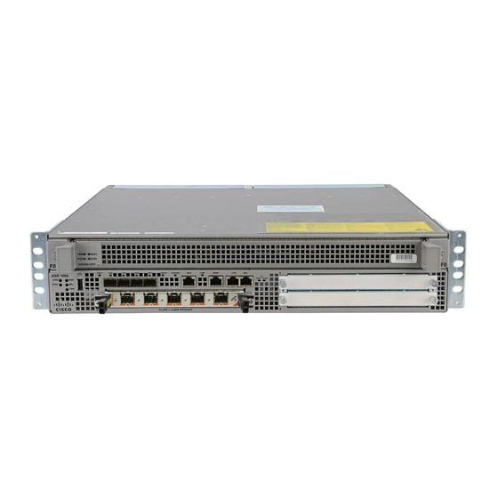
Asr 1002 router
Hide thumbs
Also See for ASR 1002:
- Hardware installation manual (57 pages) ,
- Software configuration manual (378 pages) ,
- Replacing (120 pages)
Table of Contents

Related Manuals for Cisco ASR 1002


Summary of Contents for Cisco ASR 1002
- Page 1 UICK TART UIDE Cisco ASR 1002 Router Documentation and Resources Prepare for Installation Rack-Mount the Router Connect the Router to the Network Start the System Configuring the Router After Installation...
-
Page 2: Document Revision History
Subscribe to the What’s New in Cisco Product Documentation as a Really Simple Syndication (RSS) feed and set content to be delivered directly to your desktop using a reader application. The RSS feeds are a free service and Cisco currently supports RSS... -
Page 3: Prepare For Installation
Only trained and qualified personnel should install, replace, or service this equipment. Statement 1030 Caution The eUSB panel door on the side of the Cisco ASR 1002 Router must not be opened. If there is a problem with eUSB flash card, the chassis should be returned. -
Page 4: Prepare For Rack-Mount Installation
Front rack-mount bracket screws Front rack-mount bracket e To install the rack-mount brackets on a Cisco ASR 1002 Router for a front rack-mount configuration, follow these steps: Step 1 Locate the threaded holes in the front sides of the chassis. -
Page 5: Attach The Rack-Mount Brackets-Chassis Rear-Mounted
Attach the Rack-Mount Brackets—Chassis Rear-Mounted To install the rack-mount on a Cisco ASR 1002 Router for a rear rack-mount configuration, follow these steps: Locate the threaded ear holes in the rear sides of the chassis. Step 1 Position the rear rack-mount bracket top hole with the chassis from the back (See Figure 2).Make certain that you hold... - Page 6 Figure 3 shows the Cisco ASR 1002 Router in a four-post rack. Figure 3 Installing the Cisco ASR 1002 Router in a Four-Post Rack - Front and Rear Rack-Mounting SPA-4 XOC3 -POS SPA-4 XOC3 -POS AS R 10 02 stat...
-
Page 7: Two-Post Rack Installation
Inner clearance (the width between the inner sides of the two posts or rails) must be at least 19 inches (48.26 cm). Note Airflow through the chassis is from front to back. Figure 4 Installing a Cisco ASR 1002 Router in a Two-Post Rack -POS SPA-4 XOC3 SPA-4 XOC3... -
Page 8: Attach The Cable-Management Bracket
Step 4 a. The Cisco ASR 1002 Router rack-mount bracket has 4 ear holes and two for the cable-management bracket. Insert the bottom screw into the fifth hole from the top of the rack-mount ear and use a hand-held screwdriver to tighten the screw to the rack rail. -
Page 9: Chassis Ground Connection Installation
Before you connect power or turn on power to your router, you must provide an adequate chassis ground (earth) connection for the Cisco ASR 1002 Router. The chassis ground lugs (two) and the respective screws (4) are provided in the accessory kit that ships with your Cisco ASR 1002 Router. - Page 10 SPA-4 XOC3- crit F0 with Cisco ASR1000-ESP5 or Cisco ASR1000-ESP10 The eUSB panel door on the side of the Cisco ASR 1002 Router must not be opened. If there is a problem with eUSB flash card, the chassis should be returned.
-
Page 11: Console And Auxiliary Port Cable Connections
The Cisco ASR 1002 Router uses RJ-45 ports for both the auxiliary port and console port to attach a modem or console terminal. The console DCE-mode port connects a console terminal and a DTE-mode auxiliary port connects a modem or other DCE device to your router. -
Page 12: Management Ethernet Port Cable Connection
After you establish normal router operation, you can disconnect the terminal. Step 3 For console and auxiliary port pinouts, see Cisco ASR 1002 router specifications in the Cisco ASR 1000 Series Note Aggregation Services Routers Hardware Installation and Initial Configuration Guide. -
Page 13: Connect The Shared Port Adapter Cables
Connect the Shared Port Adapter Cables The instructions for connecting the cables for the shared port adapters installed in the Cisco ASR 1002 Router are contained in the Cisco ASR 1000 Series Aggregation Services Routers SPA and SIP Hardware Installation Guide. -
Page 14: Start The System
Warning This product relies on the building’s installation for short-circuit (overcurrent) protection. Ensure that the protective device is rated not greater than: AC power supplies 20 A and DC power supplies 30 A for Cisco ASR 1002 Routers. Statement 1005 Figure 11 shows the AC power supply for the Cisco ASR 1002 Router. -
Page 15: Connect Dc Power To The Cisco Asr 1002 Router
Note To connect an AC power supply to the Cisco ASR 1002 Router, follow the steps in Installing the AC Power Supply, page Connect DC Power to the Cisco ASR 1002 Router The DC power supply input connector is a euro-style terminal block. - Page 16 LED operation before going off. To connect the DC power supply to a Cisco ASR 1002 Router, follow these steps: At the rear of the router, check that the power switch is in the standby position.
- Page 17 DC power source. Warning When you install the unit, the ground connection must always be made first and disconnected last. Figure 13 Cisco ASR 1002 Router DC Power Supply OU TP UT IN PU T FA N...
-
Page 18: Verifying Power Supply Operation
Check the following conditions before you start the Cisco ASR 1002 Router: • The Cisco ASR 1002 Router has one slot for FP0 with three subslots for SPAs, subslots 1, 2, and 3. Make certain that each shared port adapter is firmly seated in its subslot and its captive screws are securely tightened. - Page 19 Step 1 Turn on power. The green OK LED on the power supply turns on. (Both power supplies are required in the Cisco ASR 1002 Router.) Listen for the fans; you should immediately hear them operating. Step 2 During the boot process, observe the system LEDs. The power LED should be green. The STATUS LED lights yellow Step 3 to indicate booting and then green when Cisco IOS is running.
- Page 20 The system boots differently depending on the configuration that ships with your system. The display below is a snapshot of messages that are output on the console of the Cisco ASR 1002 Router system after power-up and during IOS booting. This is only an example of what you might see from any Cisco ASR 1000 Series Router.
- Page 21 If you are unable to comply with U.S. and local laws, return this product immediately. A summary of U.S. laws governing Cisco cryptographic products may be found at: http://www.cisco.com/wwl/export/crypto/tool/stqrg.html If you require further assistance please contact us by sending email to export@cisco.com.
-
Page 22: Configuring The Router
For detailed software configuration information, see the Cisco ASR 1000 series Aggregation Services Routers Software Configuration Guide. -
Page 23: Configure Global Parameters Using The Set-Up Facility
Rights clause at FAR sec. 52.227-19 and subparagraph (c) (1) (ii) of the Rights in Technical Data and Computer Software clause at DFARS sec. 252.227-7013. cisco Systems, Inc. 170 West Tasman Drive San Jose, California 95134-1706 --- System Configuration Dialog ---... - Page 24 for management of the system, extended setup will ask you to configure each interface on the system Would you like to enter basic management setup? [yes/no]: n First, would you like to see the current interface summary? [yes]: y Any interface listed with OK? value "NO" does not have a valid configuration Interface IP-Address OK? Method Status...
- Page 25 no ip address interface GigabitEthernet0/0/1 shutdown no ip address interface GigabitEthernet0/0/2 shutdown no ip address interface GigabitEthernet0/0/3 shutdown no ip address interface GigabitEthernet0/1/0 shutdown no ip address interface GigabitEthernet0/1/1 shutdown no ip address interface FastEthernet0/3/0 shutdown no ip address interface FastEthernet0/3/1 shutdown no ip address interface FastEthernet0/3/2...
- Page 26 Proceed with reload? [confirm] *Jan 11 06:59:29.476: %SYS-5-RELOAD: Reload requested by console. Reload Reason: Reload command. System Bootstrap, Version 12.2(20071105:235056) [gschnorr-mcp_rommon_rel_1_25 101], DEVELOPMENT SOFTWARE Copyright (c) 1994-2007 by cisco Systems, Inc. Compiled Mon 05-Nov-07 16:50 by gschnorr-mcp_rommon_rel_1_25 Current image running: Boot ROM1...
-
Page 27: Check The Running Configuration Settings
Basic management setup configures enough connectivity for managing the system; extended setup will ask you to Note configure each interface on the system. For detailed information about setting global parameters, refer to the Cisco ASR 1000 Series Aggregation Services Routers Software Configuration Guide. -
Page 28: Save The Running Configuration To Nvram
Follow the instructions in this section to replace field-replaceable units (FRUs) after installation. The Cisco ASR 1002 Router supports the following components as FRUs: Cisco ASR1000-ESP5, shared port adapters, and power supplies. For a complete list of Cisco ASR 1000 Series Routers field replaceable units, go to the Cisco ASR 1000 Series Note Aggregation Services Router Hardware Installation and Initial Configuration Guide, Chapter 8. -
Page 29: Power Off The Cisco Asr 1002 Router
Power Off the Cisco ASR 1002 Router This section explains how to shut down the Cisco ASR 1002 Router. It is recommended that before turning off all power to the chassis, you issue the reload command. This insures that the operating system cleans up all the file systems. Once the reload operation is complete, then the Cisco ASR 1000 Series router can be powered off safely. -
Page 30: Replace The Shared Port Adapters
Using the handles on both sides of the module, with two hands, gently insert the Cisco ESP5 or -ESP10 into the top Step 2 chassis slot. Note Handle the Cisco ESP5 and ESP10 by the carrier edges only; never touch the printed circuit board components or connector pins. -
Page 31: Replace A Power Supply In The Cisco Asr 1002 Router
Removing an AC Power Supply To remove a Cisco ASR 1002 Router AC power supply that is not operating normally (and then replace the AC power supply within five minutes), follow this procedure: Slip on the ESD-preventative wrist strap that was included in the accessory kit. - Page 32 15. Make sure the power cord is hanging loosely so that it cannot be disconnected from the AC power inlet. Figure 15 Cisco ASR 1002 Router AC Power Cord - Left and Right OU TP UT INP UT FAI L...
-
Page 33: Removing The Dc Power Supply
Removing the DC Power Supply Before you can remove a DC power supply from the Cisco ASR 1002 Router, you must remove power from the power supply. Make certain that the chassis ground is connected before you begin removing and installing the power supply. -
Page 34: Installing The Dc Power Supply
Replace the DC power supply within five minutes or the system will shutdown. Step 7 You have completed the procedure for removing a DC power supply from the Cisco ASR 1002 Router. Installing the DC Power Supply This section provides information about replacing a DC power supply in the Cisco ASR 1002 Router. - Page 35 Turn the branch circuit breaker on at your site and the turn the Standby switch to the On (I) position. Step 8 Check that the power supply LEDs light when power is supplied to the router. Step 9 You have completed the procedure for installing a DC power supply in the Cisco ASR 1002 Router.
- Page 36 31 0 800 020 0791 Fax: 408 527-0883 Fax: 31 0 20 357 1100 Cisco has more than 200 offices worldwide. Addresses, phone numbers, and fax numbers are listed on the Cisco Website at www.cisco.com/go/offices. © 2008 Cisco Systems, Inc. All rights reserved.