Cisco ASR1002 Installation Manual
Overview and installation
Hide thumbs
Also See for ASR1002:
- Software configuration manual (462 pages) ,
- Quick start manual (47 pages) ,
- Configuration manual (34 pages)
Table of Contents
Advertisement
Quick Links
Download this manual
See also:
Configuration Manual
Cisco ASR 1002 Router Overview and Installation
This chapter describes the Cisco ASR 1002 Router and provides procedures for installing the
Cisco ASR 1002 Router on an equipment shelf or tabletop or in an equipment rack.
This chapter contains the following sections:
•
•
•
•
•
•
•
•
•
•
•
•
•
•
•
•
Cisco ASR 1002 Router Description
The Cisco ASR 1002 Router is part of the Cisco aggregation services family of routers. The Cisco
ASR 1002 Router offers a compact form factor router that satisfies customer demands such as low power
consumption and decreased usage of rack space.
The Cisco ASR 1002 Router supports three half-height SPAs and an optional built-in 4xGE SPA. The
Cisco ASR 1002 Router supports all the general-purpose routing and security features of the Cisco ASR
1000 Series Routers. It uses the same internal control and data-plane architecture as the other Cisco
ASR 1000 Series Routers.
OL-13208-09
Cisco ASR 1002 Router Description, page 8-1
Installation Methods, page 8-12
General Rack Installation Guidelines, page 8-13
Equipment Shelf or Tabletop Installation, page 8-14
Rack-Mounting the Cisco ASR 1002 Router, page 8-16
Attaching the Chassis Rack-Mount Brackets, page 8-17
Attaching the Cable-Management Bracket, page 8-23
Attaching a Chassis Ground Connection, page 8-25
Connecting the Shared Port Adapter Cables, page 8-28
Cisco ASR 1002 Router Power Supplies, page 8-30
Connecting a Terminal to the Cisco ASR1000-RP1 Console Port, page 8-44
Cisco ASR 1000 Series Aggregation Services Routers Hardware Installation Guide
8
C H A P T E R
8-1
Advertisement
Table of Contents

Related Manuals for Cisco ASR1002


Summary of Contents for Cisco ASR1002
-
Page 1: Table Of Contents
• Cisco ASR 1002 Router Description The Cisco ASR 1002 Router is part of the Cisco aggregation services family of routers. The Cisco ASR 1002 Router offers a compact form factor router that satisfies customer demands such as low power consumption and decreased usage of rack space. -
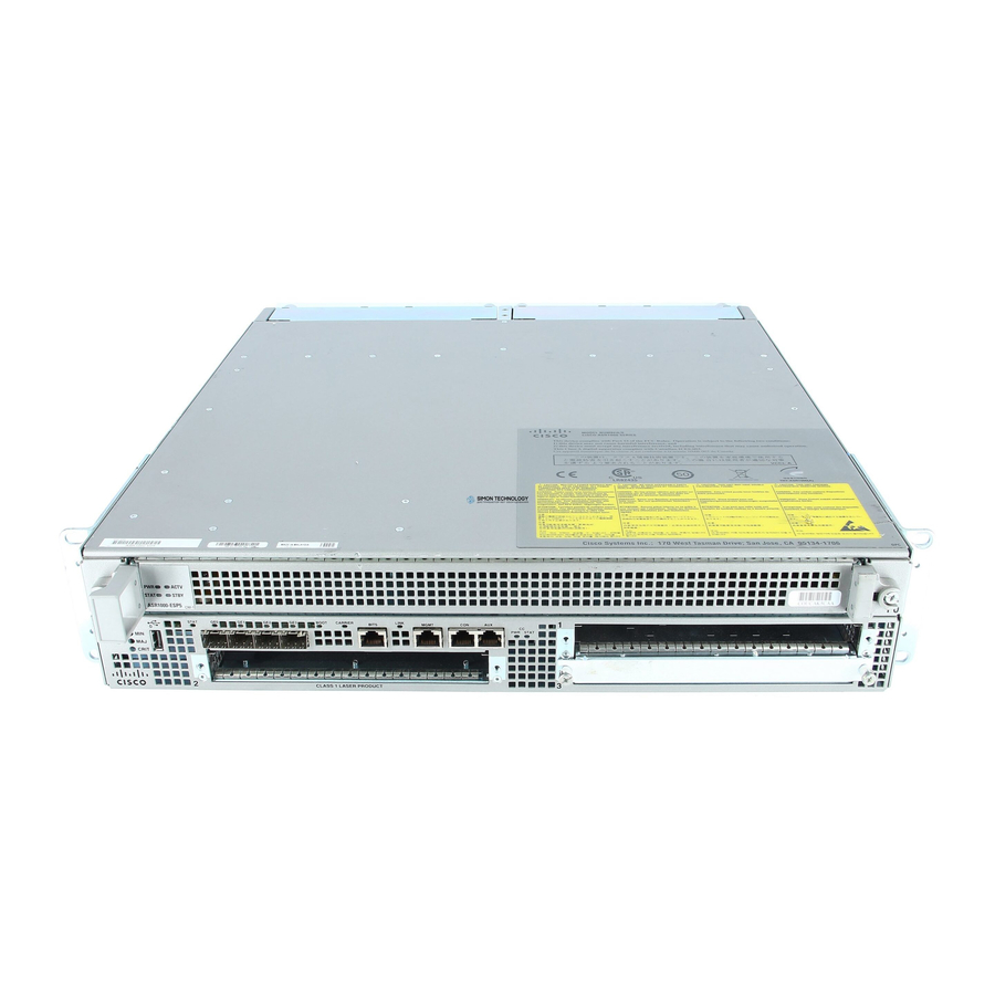
Page 2: Front View
The SPAs in subslots 1-3 are field upgradeable. The SIP that the SPAs reside in is not field-upgradeable and the Cisco ASR 1000 Series Route Processor is embedded in the chassis and not field upgradeable. Cisco ASR 1000 Series Aggregation Services Routers Hardware Installation Guide Cisco ASR 1002 Router—Front View... - Page 3 All connections must be removed to de-energize the unit. -48V/-60V 10 Negative lead Cisco ASR 1000 Series Aggregation Services Routers Hardware Installation Guide Cisco ASR 1002 Router Description OUTPUT INPUT FAIL This unit might have more than one power supply connection.
-
Page 4: Cisco Asr 1002 Router Components
Two power supplies, either two AC power supplies or two DC power supplies are accessed from the rear of the router. Use only AC power supplies or DC power supplies in the Cisco ASR 1002 Router. Do not mix power Caution supply types. - Page 5 Cisco ASR 1002 Router Overview and Installation Cisco Embedded ASR1000-RP1 for Cisco ASR 1002 Router Description The Cisco ASR 1000 Series route processor (embedded for the Cisco ASR 1002 Router) is the central control processor and runs the network operating system.
-
Page 6: Power Supplies In The Cisco Asr 1002 Router
STATUS STBY Standby The Cisco ASR 1000-ESP5 can only be used in the Cisco ASR 1002 Router. Note Power Supplies in the Cisco ASR 1002 Router The Cisco ASR 1002 Router power supply module supports the following Cisco power supplies: AC power supply operates between 85VAC to 264VAC and DC operates between –40.5 to –72VDC... - Page 7 Cisco ASR 1002 Router Overview and Installation The power supplies are installed into the rear of the chassis and are hot pluggable. The Cisco ASR 1002 Router supports up to 588 W input power from an infrastructure standpoint (cooling capacity, midplane and power distribution) but initial power supply development limit is up to 470 W output (AC and DC Input).
- Page 8 DC input wiring. The connection order is negative (–), positive (+), and GND. The DC power supply is secured into the system chassis with two captive screws mounted on the faceplate. Figure 8-7 shows the –48 VDC Power Supply for the Cisco ASR 1002 Router. Figure 8-7 Chassis ESD socket...
- Page 9 +24 VDC Power Supply for Cisco ASR 1002 Router This section provides information about the +24 VDC power supplies on the rear of the Cisco ASR 1002 Router. The recommended branch circuit breaker for the Cisco ASR 1002 Router +24 VDC power supply is a 40 A UL listed circuit breaker.
- Page 10 Cisco ASR 1002 Router Description The Cisco ASR 1002 Router has two of the same type power supplies in power supply slot 0 and power supply slot 1. The power supply slot identifiers are zero (0) on the left side of the chassis rear and one (1) on the right side of the chassis rear.
- Page 11 Chapter 8 Cisco ASR 1002 Router Overview and Installation The Cisco ASR 1002 Router +24 VDC power supply LEDs are defined in Table 8-5 Cisco ASR 1002 Router +24 VDC Power Supply LEDs LED Label OUTPUT FAIL Power supply activity...
-
Page 12: Installation Methods
Any combination of output voltage/currents cannot exceed total power rating of 470 Watts. Note +24 VDC Power Supply Important Notices The following items list important notes regarding the +24 VDC power supply in the Cisco ASR 1002 Router: Output Voltage Alarm Threshold—The Output Voltage Alarm is declared when the output voltage •... -
Page 13: General Rack Installation Guidelines
General Rack Installation Guidelines When planning your rack installation, consider the following guidelines: The Cisco ASR 1002 Router requires a minimum of 3.5 inches or 8.9 cm rack units of vertical rack • space. Measure the proposed rack location before mounting the chassis in the rack. -
Page 14: Guidelines For An Equipment Shelf Or Tabletop Installation
When installing the Cisco ASR 1002 Router on an equipment shelf or tabletop, ensure that the surface is clean and that you have considered the following: The Cisco ASR 1002 Router requires at least 3 inches (7.62 cm) of clearance at the inlet and exhaust •... - Page 15 Gather the two cable-management brackets and screws shipped with your chassis. Step 5 cable-management brackets attached on the front of the Cisco ASR 1002 Router. Make certain that the cable-management ‘U’ feature device has the open end pointing upwards Note...
-
Page 16: Rack-Mounting The Cisco Asr 1002 Router
Step 8 Rack-Mounting the Cisco ASR 1002 Router The Cisco ASR 1002 Router can be installed in an existing rack with equipment or in an empty rack with no equipment: The chassis can be mounted in either rack types: Two-post rack, either 19 inch or 23 inch. Inner clearance (the width between the inner sides of the •... -
Page 17: Attaching The Chassis Rack-Mount Brackets
Chapter 8 Cisco ASR 1002 Router Overview and Installation The Cisco ASR 1002 Router can be installed with both front or rear rack-mount brackets. Verifying Rack Dimensions Before you install the chassis, measure the space between the vertical mounting flanges (rails) on your equipment rack to verify that the rack conforms to the measurements shown in Mark and measure the distance between two holes on the left and right mounting rails. - Page 18 Repeat Step 1 through Step 3 on the other side of the chassis. Use black screws to secure the rack-mount Step 4 brackets to the chassis. Install the chassis in a rack. To install the Cisco ASR 1002 Router in a rack, go to the Step 5 Cisco ASR 1002 Router in a Rack” section on page This completes the steps for attaching the front rack-mount brackets to the Cisco ASR 1002 Router.
-
Page 19: Installing The Cisco Asr 1002 Router In A Rack
This completes the steps for attaching the rear rack-mount brackets to the Cisco ASR 1002 Router. To make installation easier, before you mount the ASR 1002 Router in a rack, make certain you read Caution which rack-mount bracket ear holes to use when positioning the chassis in the rack. - Page 20 See the next sections on the types of racks you can use to install the chassis. (Optional) Install a shelf in the rack to support the Cisco ASR 1002 Router. If you use a shelf, this will Step 3 help support the chassis while you secure it to the rack.
-
Page 21: Two-Post Rack Installation
Two-Post Rack Installation The Cisco ASR 1002 Router can be installed on a two-post rack, either 19 inch or 23 inch. Inner clearance (the width between the inner sides of the two posts or rails) must be at least 19 inches Note (48.26 cm). -
Page 22: Four-Post Rack Installation
Make sure the rack is stabilized. Note (Optional) Install a shelf in the rack to support the Cisco ASR 1002 Router. If you are using a shelf then Step 1 raise the chassis to the level of the shelf. Let the bottom of the chassis rest on the brackets, but continue to support the chassis. -
Page 23: Attaching The Cable-Management Bracket
The cable-management brackets for the Cisco ASR 1002 Router contain one independent cable-management “U” type features with four screws and provides cable dressing of each card module slot. - Page 24 Note to the chassis. Follow these steps to attach the cable-management brackets to both sides of the Cisco ASR 1002 Router in the rack: Align the cable-management bracket to the rack-mount bracket on one side of the Cisco ASR 1002 Step 1 Router.
-
Page 25: Attaching A Chassis Ground Connection
Cisco ASR 1002 Router Overview and Installation Attaching a Chassis Ground Connection Connecting the Cisco ASR 1002 chassis to ground is required for all DC powered installations and any AC powered installation where compliance with Telcordia grounding requirements is necessary. - Page 26 Attaching a Chassis Ground Connection Figure 8-17 shows the location of the dual ground lug on the side of the of Cisco ASR 1002 Router. Figure 8-17 F0 with ASR1000-ESP5 or ESP10. R0 slot with embedded ASR1000-RP1 and embedded ASR1000-SIP10.
- Page 27 Locate the chassis ground connector on the side of your chassis. Step 4 OL-13208-09 Parts of the Grounding Lug Cisco ASR 1000 Series Aggregation Services Routers Hardware Installation Guide Attaching a Chassis Ground Connection Ground lug screws Ground wire 8-27...
-
Page 28: Connecting The Shared Port Adapter Cables
Connecting the Shared Port Adapter Cables The instructions for connecting the cables for the shared port adapter installed in the Cisco ASR 1002 Router are contained in the respective configuration documents for each port adapter. For example, if... -
Page 29: Connecting The Console And Auxiliary Port Cables
This section describes how to attach a cable to the Cisco embedded ASR1000-RP1 console or auxiliary ports on the Cisco ASR 1002 Router. The Cisco ASR 1002 Router uses RJ-45 ports for both the auxiliary port and console port to attach a modem or console terminal. -
Page 30: Cisco Asr 1002 Router Power Supplies
Insert the other end of the RJ-45 cable to your management device or network. Step 2 Cisco ASR 1002 Router Power Supplies This section describes the Cisco ASR 1002 Router power supplies and how to connect them: Connecting AC Input Power to Cisco ASR 1002 Router, page 8-31 •... - Page 31 This section provides the procedures for connecting AC-input, –48 VDC input power, and the +24 VDC input power to your Cisco ASR 1002 Router. Detailed instructions for removing and replacing the Cisco ASR 1002 Router AC and DC power supplies Note are in Chapter 13, “Removing and Replacing FRUs from the Cisco ASR 1000 Series Routers.”...
- Page 32 Cisco ASR 1002 Router Power Supplies Figure 8-22 shows the various parts of the Cisco ASR 1002 Router AC power supply. Figure 8-22 Chassis ESD socket AC power supply slot number 0 AC power supply On (|) /Off (O) switch...
- Page 33 -e ne be re mo ve rg ize the un it. Cisco ASR 1002 Router AC Power Supply in Slot 0 and Slot 1 With Power Cord OU TPU T INP UT FAI L Thi s uni t...
- Page 34 The order the leads should be attached is GND, positive (+), and negative (-). The recommended branch circuit breaker for the Cisco ASR 1002 Router –48 VDC power supply is 30 A. Use a AWG #10 wire gauge on the 30 A circuit.
- Page 35 3 –48 VDC power supply switch Standby/On 4 –48 VDC power supply LEDs 5 Fan Table 8-9 describes the LEDs on the Cisco ASR 1002 Router –48 VDC power supply. Table 8-9 Cisco ASR 1002 Router –48 VDC Power Supply LEDs LED Label...
- Page 36 Power supply activity FAIL This section describes how to connect the –48 VDC power supply in the Cisco ASR 1002 Router. The color coding of the –48 VDC input power supply leads depends on the color coding of the –48 VDC Note power source at your site.
- Page 37 Connect the ground, positive, and negative leads to the power source. Step 7 OL-13208-09 Cisco ASR 1002 Router –48 VDC Power Supply Terminal Block Cable Connections Cisco ASR 1000 Series Aggregation Services Routers Hardware Installation Guide Cisco ASR 1002 Router Power Supplies...
- Page 38 Place the –48 VDC Standby switch in the On (|) position. The power supply LEDs light when power is Step 9 supplied to the router. You have completed the procedure for connecting a –48 VDC power supply in the Cisco ASR 1002 Router. Connecting Cisco +24 VDC Power Supply The +24 VDC power supply uses a spring-loaded terminal block.
- Page 39 5 Power supply LEDs This section describes how to connect the +24 VDC power supply in the Cisco ASR 1002 Router. The color coding of the +24 VDC input power supply leads depends on the color coding of the +24 VDC Note power source at your site.
- Page 40 Check that there is no copper portion of the lead wire exposed. You only want the wire insulation visible. Do not install wire into the terminal block that has not had its insulation removed. Caution Cisco ASR 1000 Series Aggregation Services Routers Hardware Installation Guide 8-40 Chapter 8 Stripping Wire for the +24 VDC Terminal Block —...
- Page 41 Once the screwdriver is completely removed, gently pull on the lead wire to make certain that the lead wire is securely installed. OL-13208-09 Cisco ASR 1002 Router +24 VDC Power Supply Lead Wire Inserted into Terminal Block T h is u n o n e p o w...
- Page 42 Repeat Steps 5 through Step 10 for each lead wire. Step 8 Figure 8-34 shows all the lead wires installed. Cisco ASR 1000 Series Aggregation Services Routers Hardware Installation Guide 8-42 Chapter 8 Removing a Screwdriver from the +24 VDC Power Supply Terminal Block...
- Page 43 (GND) lead to ensure that the ground lead is the last lead wire to disconnect from the power supply if a great deal of strain is placed on all three leads. OL-13208-09 Cisco +24 VDC Power Supply Terminal Block With Lead Wires Installed O U T P U T IN P U...
- Page 44 CON on its front panel. You can connect this port to most types of video terminals through use of the console cable kit that is included with your Cisco ASR 1002 Router. The console cable kit contains:...
- Page 45 (pin 1) is the same color as the wire connected to the outside (right) pin of the right plug (pin 8). Use the following procedure to connect a video terminal to the console port on a route processor. Each Cisco ASR 1000 Series Route Processor 1 must have a console port connection (typically to a Note terminal server) if you are running a redundant configuration in the chassis.
-
Page 46: Connecting Cables
Cisco ASR 1002 Router to a modem. Step 1 Connect one end of the modem cable to the RJ-45 port on the primary Cisco ASR 1000 Series Route Processor 1, labeled AUX. For the AUX port connection, see Run the cable up and through the cable-management bracket and connect the other end of the cable to Step 2 your modem.