Advertisement
Quick Links
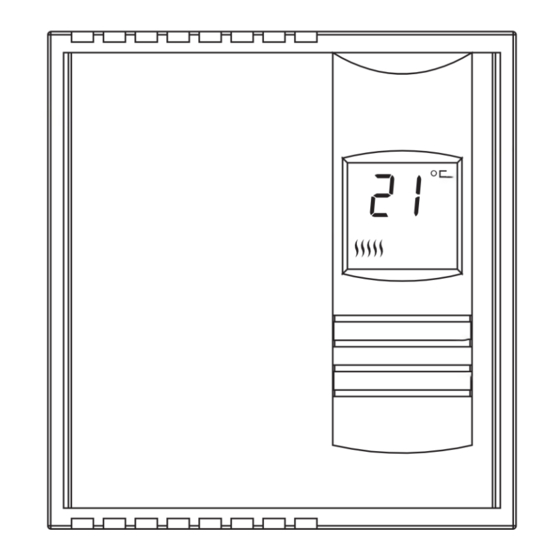
Heating power
indicator
Description
This thermostat can be used to control a electric heating system such
as an baseboard heater, a radiant ceiling, a radiant floor, a convector,
etc. See minimum and maximum load requirement in section 5.
The thermostat cannot be used with the following:
•
a resistive load under 2 A
•
systems driven by a contactor or a relay (inductive load)
•
fan-equipped heating systems
•
central heating systems
SUPPLIED PARTS
•
One (1) thermostat
•
Two (2) 6-32 mounting screws
•
Two (2) solderless connectors
Installation
TURN OFF POWER OF THE HEATING SYSTEM AT THE MAIN
POWER PANEL TO AVOID ELECTRIC SHOCK.
Loosen the screw holding the control module to the base. The screw
cannot be completely removed. Lift the control module to remove it
from the base.
Make the appropriate connections. Please note that the thermostat
wires are non-polarized; either wire can be connected to either termi-
nal.
RLV310
NOTE:
cal code. Special CO/ALR solderless connectors must be used when
connecting with aluminium conductors.
Temperature
display
Temperature
adjustment
2-wire installation
buttons
1.
4-wire installation
Align and affix the base to the
electrical box.
2.
Set the switch at the back of the remov-
able part of the thermostat to °C or °F.
Replace the front part of the thermostat
on the base and secure it in place with
the screw.
Keep air vents of thermostat clean and
free from obstructions.
All cables and connections must conform to the local electri-
69-1854
RLV310
User Guide
Electronic Thermostat
6/27/05
1/2
Advertisement

Related Manuals for Honeywell RLV310


Summary of Contents for Honeywell RLV310
-
Page 1: User Guide
Heating power indicator Description This thermostat can be used to control a electric heating system such as an baseboard heater, a radiant ceiling, a radiant floor, a convector, etc. See minimum and maximum load requirement in section 5. The thermostat cannot be used with the following: •... -
Page 2: Temperature Display And Setting
(ii) call Honeywell Customer Care at 1-800-468-1502. Customer This warranty does not cover removal or reinstallation costs. This warranty shall not apply if it is shown by Honeywell that the defect or malfunction was caused by damage which occurred while the prod- uct was in the possession of a consumer.