Table of Contents
Advertisement
Quick Links
Dell™ PowerConnect™ 3324/3348 User's Guide
Overview
Hardware Description
Installing the PowerConnect 3324/3348 Switch
Configuring the PowerConnect 3324/3348 Switch
Getting Started
Configuring System Information
Configuring Switch Information
Viewing Statistics
Configuring Quality of Service
Getting Help
NOTE:
Notes indicate important information that helps you make better use of your device.
NOTICE:
Notices indicate either potential damage to hardware or loss of data and tells you how to avoid the problem.
CAUTION:
Caution indicates a potential for property damage, personal injury, or death.
Information in this document is subject to change without notice.
© 2003 Dell Inc. All rights reserved.
Reproduction in any manner whatsoever without the written permission of Dell Inc. is strictly forbidden.
Trademarks used in this text: Dell, the DELL logo, PowerConnect, Dell OpenManage, PowerEdge, Inspiron, Dell Precision, Dimension, OptiPlex, Axim, PowerVault, PowerApp, DellNet, and
Latitude are trademarks of Dell Inc.; Microsoft and Windows are registered trademarks of Microsoft Corporation.
Other trademarks and trade names may be used in this document to refer to either the entities claiming the marks and names or their products. Dell Inc. disclaims any
proprietary interest in trademarks and trade names other than its own.
November 2003
Advertisement
Table of Contents

Related Manuals for Dell PowerConnect 3324


Summary of Contents for Dell PowerConnect 3324
- Page 1 Latitude are trademarks of Dell Inc.; Microsoft and Windows are registered trademarks of Microsoft Corporation. Other trademarks and trade names may be used in this document to refer to either the entities claiming the marks and names or their products. Dell Inc. disclaims any proprietary interest in trademarks and trade names other than its own.
-
Page 2: Configuration Overview
Back to Contents Page Configuring the PowerConnect 3324/3348 Switch Dell™ PowerConnect™ 3324/3348 User's Guide Configuration Overview Sample Configuration Process General Configuration Information Configuring Stacking Terminal Connection Configuration Rebooting the Device Other Configuration Requirements Startup Menu Functions Booting the Device Downloading the Software to Stacking Units Device Configuration Introduction... -
Page 3: General Configuration Information
General Configuration Information Dell™ PowerConnect™ 3324/3348 is provided with pre-defined implemented features and setup configuration. Auto-Negotiation Auto-negotiation allows a device to advertise modes of operation and share information with another device that shares a point-to-point link segment. This automatically configures both devices to take maximum advantage of their abilities. -
Page 4: Baud Rate
console> enable console# configure Console (config)# interface ethernet 1/e5 Console (config-if)# flowcontrol on The following is an example for enabling back pressure on port 1/e5 using CLI commands: console> enable console# configure Console (config)# interface ethernet 1/e5 ... -
Page 5: Terminal Connection Configuration
console(config-if)# exit console(config)# exit Terminal Connection Configuration The PowerConnect 3324/3348 requires the following Terminal Connection parameters for configuration: no parity one stop bit 8 data bits Other Configuration Requirements The following is required for downloading embedded software and configuring the device: ASCII terminal (or emulation) connected to the Serial port in the back of the unit. - Page 6 Boot1 Checksum Test..PASS Boot2 Checksum Test..PASS Flash Image Validation Test..PASS Testing CPU PCI Bus Device Configuration...PASS BOOT Software Version 1.30.11 Built 27-JAN-2003 10:06:03 Processor: MPC8245 Rev 0.12, 250 MHz (Bus: 100MHz), 32 MByte SDRAM. ...
- Page 7 Base Mac address is: 00:01:02:03:04:05 Dram size is: 32M bytes Dram first block size is: 20M bytes Dram first PTR is: 0xB70000 Flash size is: 8M STAND ALONE The BCM5625_A1 0 initiate successfully ...
-
Page 8: Device Configuration Introduction
After the device has been booted successfully, the system prompt appears (console>) and the configuration process can be started. The local terminal can be used for configuration. Device Configuration Introduction There are two types or levels of configuration. The initial configuration describes basic configuration functions with basic security considerations. The advanced configuration includes dynamic IP configuration and more advanced security considerations. - Page 9 console# show ip interface Gateway IP Address Activity status ----------------------- ----------------------- IP Address I/F ----------------------- ---------------------- 100.1.1.1/8 vlan 1 console# To configure an interface on a port, enter the commands at the system prompt as shown in the following configuration example: ...
-
Page 10: Default Gateway
----------------------- ---------------------- 10.1.1.1/8 1/e1 console# Default Gateway To manage a PowerConnect 3324/3348 device from a remote network, a default gateway, which is the gateway that a device uses if a specific gateway is not specified, must be configured. - Page 11 Simple Network Management Protocol (SNMP) provides a method for managing network devices. Devices supporting SNMP run a local software (agent). The SNMP agents maintain a list of variables, used to manage the device. The variables are defined in the Management Information Base (MIB). The MIB presents the variables controlled by the agent.
-
Page 12: Advanced Configuration
config# configure config(config)# snmp-server community private rw 11.1.1.2 config(config)# exit config# show snmp Community-String Community-Access IP address -------------------- ---------------- --------------- private readWrite 11.1.1.2 Traps are enabled. Authentication-failure trap is enabled. Trap-Rec-Address Trap-Rec-Community Version ... - Page 13 When using the DHCP protocol to retrieve an IP address, the device acts as a DHCP client. To retrieve an IP address from a DHCP server: 1. Select and connect any port to a DHCP server or to a subnet which has a DHCP server on it, in order to retrieve the IP address. 2.
-
Page 14: Receiving An Ip Address From A Bootp Server
Receiving an IP address from a BOOTP Server The standard BOOTP protocol is supported enabling the device to automatically download their IP host configuration from any standard BOOTP server in the internet. In this case, the device acts as a BOOTP client. ... -
Page 15: Security Management And Password Configuration
The device configuration must be deleted to retrieve an IP address from the BOOTP server. Security Management and Password Configuration System security is handled through the AAA (Authentication, Authorization and Accounting) mechanism that manages user access rights, privileges and management methods. -
Page 16: Configuring An Initial Telnet Password
console(config-line)# password console console(config-line)# exit console(config)# exit When initially logging on to a device through a console session, enter console at the password prompt. When changing a device's mode to enable, enter console at the password prompt. Configuring an Initial Telnet Password ... -
Page 17: Configuring An Initial Http Password
console(config)# aaa authentication login default line console(config)# aaa authentication enable default line console(config)# line ssh console(config-line)# login authentication default console(config-line)# enable authentication default console(config-line)# password admin console(config-line)# exit console(config)# exit When initially logging onto a device through a SSH session, enter admin as the password. When changing a device's mode to enable, enter admin as the password. -
Page 18: Sample Configuration Process
console(config)# username admin password admin level 15 console(config)# exit Enter the following commands once when configuring a console, a telnet, or an SSH session in order to use an HTTPS session. NOTE: In the Web browser, enable SSL 2.0 or greater for the content of the page to appear. ... - Page 19 1. Connect the PowerConnect 3324/3348 device to the RS232 interface of a computer operating as an ASCII terminal. 2. Set the ASCII terminal with the following settings and select the appropriate COM port (In this example using Windows Hyper Terminal application): ...
- Page 20 Flash Image Validation Test.......PASS Testing CPU PCI Bus Device Configuration..PASS BOOT Software Version 1.0.0.13 Built 11-May-2003 14:58:20 Processor: MPC8245 Rev 0.14, 250 MHz (Bus: 100MHz), 32 MByte SDRAM. I-Cache 16 KB, linesize 32.D-Cache 16 KB, linesize 32. ...
- Page 21 Base Mac address is: 00:06:5b:ff:59:4d Dram size is : 32M bytes Dram first block size is : 20M bytes Dram first PTR is : 0xB20000 Flash size is: 8M STAND ALONE The BCM5615_A1 0 initiate successfully ...
-
Page 22: Device Default Settings
01-Jan-2000 01:01:13 %LINK-W-Down: 1/g1 01-Jan-2000 01:01:13 %LINK-W-Down: 1/g2 01-Jan-2000 01:01:14 %LINK-I-Up: Vlan 1 01-Jan-2000 01:01:14 %LINK-I-Up: 1/e1 console> The device is ready for configuration. Device Default Settings To return to device default settings use delete startup-config command at the privileged mode prompt (#), and reboot the device. Once device reloads—it is set with the default settings. -
Page 23: Remote Management Access
Remote Management Access To allow remote device management (Telnet, Web etc.) perform the following: 1. Enter the command enable at the console to enter the Privileged EXEC screen mode as follows: console>enable console# 2. - Page 24 console (config)# exit 5. Define an IP address on the device by assigning an IP address to the interface connected to the management station (in this example 50.1.1.1). If the management station is connected directly to the interface, the IP address on the interface must have the same subnet as the management station. ...
- Page 25 8. Define a username and password to allow full (privileged level 15) device access for a remote user (telnet, Web Server etc.). In this example the username and password is "Dell". console# console# configure console(config)# username Dell password Dell level 15 console(config)# 9. Configure Console, Telnet, SSH, HTTP, and HTTPS security passwords: console> enable ...
- Page 26 console(config-line)# password admin console(config-line)# exit console(config)# aaa authentication login default line console(config)# aaa authentication enable default line console(config)# line telnet console(config-line)# login authentication default console(config-line)# enable authentication default console(config-line)# password admin console(config-line)# exit ...
-
Page 27: Start Running The Management Station
console(config)# ip https server console(config)# exit console# copy running-config startup-config The device is now configured and is ready for running the Web Management Interface. Start Running the Management Station To start running the device perform the following: 1. -
Page 28: Telnet Access
2. Enter the command Telnet and the device IP address. Microsoft Windows 2000 [Version 5.00.2195] (C) Copyright 1985-2000 Microsoft Corp. C:\>telnet 50.1.1.2 01-Jan-2000 02:40:23 %MSCM-I-NEWTERM: New TELNET connection from 50.1.1.2 User Name:Dell Password:**** console# show ip interface ... - Page 29 Gateway IP Address Activity status ----------------------- ----------------------- 50.1.1.100 inactive IP Address I/F ----------------------- ---------------------- 50.1.1.1/8 vlan 1 console# Notice that Device indicates (In ASCII terminal) Telnet session status: console>...
- Page 30 Logging on Interface 3. When the authentication window is displayed, enter the Username and password: Password Prompt The device Web Management Interface is displayed.
-
Page 31: Configuring Stacking
PowerConnect 3324/3348 Web Management Interface The PowerConnect 3324/3348 Interface Components Table lists the interface components with their corresponding numbers: Configuring Stacking Stacking Introduction Stacked PowerConnect 3324/3348 units act as a single system. Each stack has one Master unit, and up to five Member units. The Master unit: Manages all member device setup. -
Page 32: Configuring A Stack
All units are powered up. After a few seconds, the Unit ID LEDs flashes. Each Member unit has a unit ID. For more information about selecting Unit IDs, see "Stack ID Button". Configuring a Stack This section contains instructions for configuring a stack. To configure a stack: ... -
Page 33: Startup Menu Functions
Startup Menu Functions From the Startup Menu, additional device configuration functions are performed. The Startup Menu displays the following configuration functions: Downloading the Software Erasing the FLASH File Erasing FLASH Sectors The screen below illustrates the Startup Menu: ... -
Page 34: Erasing The Flash File
NOTE: The <Return> or <Esc> key must be pressed within 2 seconds in order to display the Startup menu. NOTE: The device times out after 35 seconds if no selection is made. The time out periods can be reset using the CLI. 5. -
Page 35: Password Recovery
NOTE: To ensure device security, redefine the Console Access Method passwords. For more information about configuring user passwords, see the CLI User's Guide. Running Diagnostics Contact Dell technical support before using this option. See "Contacting Dell". ... -
Page 36: Downloading The Software To Stacking Units
The software is downloaded from a TFTP server to all stacking units via one of the following methods: Sequentially using the CLI Individually using the CLI Via the Dell OpenManage™ Switch Administrator Downloading the Software Sequentially Using the CLI 1. Ensure that an IP address is assigned to at least one port on the Master unit. -
Page 37: Downloading The Software Individually Using The Cli
Copy: 2739187 bytes copied in 00:01:13 [hh:mm:ss] 5. Enter console# copy tftp://50.1.1.2/332448-10018.dos unit://2/image. The device software is copied to the Stacking member 2. unit: the //2/image indicates the Stacking member Unit ID to which the software is copied. The following is an example of the information that displays: ... - Page 38 Unit Active image Selected for next boot ----------------------------------------------------- 1 image-2 image-2 2 image-1 image-1 Both the active Image file and the Image file that is active after the device is reset are displayed for all units. 4.
-
Page 39: Defining Snmp Settings
14. Repeat steps 2 and 3 to ensure the correct Image file is active. Downloading the Software Via the PowerConnect 3324/3348 Dell OpenManage Switch Administrator For instructions on downloading the software via the Dell OpenManage Switch Administrator, see "Managing Files". Defining SNMP Settings ... - Page 40 After assigning IP addresses to the PowerConnect device, devices are connected to the RJ-45 connectors on the PowerConnect front panel. NOTICE: If auto negotiation is disabled for an RJ-45 port, the auto-MDI/MDI-X pin signal configuration is also disabled. ...
-
Page 41: Configuring Quality Of Service
Back to Contents Page Configuring Quality of Service Dell™ PowerConnect™ 3324/3348 User's Guide Quality of Service (QoS) Overview Defining QoS Global Parameters Mapping to Queues This section provides information for defining and configuring Quality of Service (QoS) parameters. Click Quality of Service in the Tree View. The Quality of Service page opens. - Page 42 QoS includes traffic such as voice, video, and real-time traffic that can be assigned a high priority queue, while other traffic can be assigned a lower priority queue. The result is an improved traffic flow for traffic with high demand. ...
-
Page 43: Defining Qos Global Parameters
DSCP mapping is enabled on a per-system basis. QoS Services After packets are assigned to a specific queue, QoS services can be assigned to the queue(s). Output queues are configured with a scheduling scheme by one of the following methods: Strict Priority—Ensures that time-sensitive applications are always forwarded via an expedited path. - Page 44 QoS Global Settings Page The QoS Global Settings page contains the following fields: Quality of Service—Enables managing network traffic using QoS. The field value options are: Enable—Enable QoS on the device. ¡ Disable—Disable QoS on the device. ¡ Trust Mode—Determines which packet fields to use for classifying packets entering the switch.
-
Page 45: Defining Qos Interface Settings
Enabling Trust Using the CLI Commands The following table summarizes the equivalent CLI commands for configuring fields in the QoS Global Settings page. CLI Command Description qos trust [cos | dscp | tcp-udp-port] Configures the system to basic mode and the trust state. qos ... - Page 46 Interface Settings Page The QoS Interface Settings page contains the following fields: Interface—Indicates the specific interface to which the Trust mode is applied. The trust mode is applied to: Port—Indicates the port number. ¡ LAG—Indicates the LAG number. ¡ VLAN—Indicates the VLAN number.
-
Page 47: Defining Queue Settings
qos cos default-cos Configures the default port CoS value. no qos trust Disables Trust state on each port. The following is an example of the CLI commands: Console (config)# interface ethernet 1/e5 Console (config-if)# qos trust Console (config-if)# qos cos 3 ... - Page 48 WRR Weight—Assigns WRR weights to egress queues. The possible field values are 1–255, where 1 is the lowest value and 255 is the highest value. % of WRR Bandwidth—Indicates the amount of bandwidth assigned to the WRR. Defining the Queue Settings: 1.
-
Page 49: Mapping To Queues
0 - 2 1 - 1 2 - 1 3 - 2 4 - 2 5 - 3 6 - 3 7 - 3 Mapping to Queues The Mapping to Queue page contains links to pages for mapping CoS and DSCP values, as well as TCP and UDP ports to QoS queues. To open the Mapping to Queue page: Select Quality of Service >... -
Page 50: Mapping Cos Values To Queues
Mapping to Queue Page The Mapping to Queue page includes links to the following topics: Mapping CoS Values to Queues Mapping TCP Port Values to Queues Mapping DSCP Values to Queues Mapping UDP Port Values to Queues Mapping CoS Values to Queues ... - Page 51 CoS to Queue Mapping Table Page The CoS to Queue Mapping Table page contains the following fields: Class of Service—Specifies the CoS priority tag values, where zero is the lowest and seven is the highest. Queue—Indicates the traffic forwarding queue to which the CoS priority is mapped. Four traffic priority queues are supported. ...
-
Page 52: Mapping Dscp Values To Queues
The following is an example of the CLI commands: Console (config)# wrr queue cos-map 4 7 Mapping DSCP Values to Queues The DSCP Mapping page allows network managers to determine the output queue that is assigned per a specific DSCP field. To open the DSCP Mapping page: ... -
Page 53: Mapping Tcp Port Values To Queues
2. Select a value in the DSCP In column. 3. Define the Queue fields. 4. Click Apply Changes. The DSCP is not overwritten, and the value is assigned a forwarding queue. Assigning DSCP Values Using the CLI Commands The following table summarizes the equivalent CLI commands for configuring fields in the DSCP Mapping page. - Page 54 The TCP to Queue page contains the following information: Select TCP Port from List—Provides a drop-down list of predefined commonly used TCP ports. Insert TCP Port—Enables defining a new TCP port. Map to Queue—Indicates the traffic queue to which the TCP port is assigned. ...
-
Page 55: Mapping Udp Port Values To Queues
The following table summarizes the equivalent CLI commands for configuring fields in the TCP to Queue page. CLI Command Description qos map tcp-port-queue port1.port8 to queue-id Modifies the TCP-Port to queue. show qos map tcp-port-queue Displays the TCP-Port to queue. no qos map tcp-port-queue ... - Page 56 UDP to Queue Page The UDP to Queue page contains the following fields: Select UDP from the List—Provides a drop-down list of predefined commonly used UDP ports. Insert UDP Port—A new UDP port may be defined. Map to Queue—Indicates the traffic queue to which the UDP port is assigned. ...
- Page 57 2. Select a port mapping in the UDP Port List drop-down list. The queue to which the port is assigned displays in the Map to Queue drop-down list. 3. Select a new traffic queue in the Map to Queue drop-down list. 4.
-
Page 58: Configuring Switch Information
Back to Contents Page Configuring Switch Information Dell™ PowerConnect™ 3324/3348 User's Guide Configuring Network Security Configuring Ports Configuring Address Tables Configuring GARP Configuring the Spanning Tree Protocol Configuring VLANs Aggregating Ports Multicast Forwarding Support This section provides all system operation and general information for configuring network security, ports, Address tables, GARP, VLANs, Spanning Tree, Port Aggregation, and Multicast Support. -
Page 59: Network Security Overview
Network Security Page The Network Security page contains links to the following topics: Network Security Overview Configuring Port Security Defining IP-Based ACLs Defining MAC-Based ACLs Binding ACLs Network Security Overview Access Control Lists (ACLs) allow network managers to define classification actions and rules for specific ingress ports. ACLs contain multiple classification rules and actions. -
Page 60: Configuring Port Security
first ACE. When a packet is matched to an ACE classification, the ACE action is taken, and the ACL processing stops. If a match is not found, the packet is dropped as a default action. If several ACLs are to be processed, the default action is applied only after processing all the ACLs. The default drop action forwards all permitted traffic, including management traffic such as Telnet, HTTP, or SNMP, to the switch. - Page 61 Interface—Indicates the selected interface type on which locked port is enabled. Port—Indicates the selected interface type is a port. ¡ LAG—Indicates the selected interface type is a stack member. ¡ Current Port Status—Indicates the current port status. Set Port—Indicates that the port is either locked or unlocked. The possible field values are: Unlocked—Unlocks Port.
-
Page 62: Defining Ip-Based Acls
CLI Command Description shutdown Disables interfaces. set interface active {ethernet interface | port-channel port-channel- Reactivates an interface that is shutdown due to port security reasons. number} port security <options> trap frequency Locks learning of new addresses on an interface. show ports security ... - Page 63 Add ACE to IP Based ACL Page The Add ACE to IP Based ACL page contains the following fields: ACL Name—Contains a list of user-defined ACLs. New ACE Priority—Defines the ACE priority. ACEs are checked on the first fit basis. The ACE priority defines the ACE order in the ACL list. Protocol—Enables creating an ACE based on a specific protocol.
- Page 64 2. Click Add. The Add ACE to IP Based ACL page opens. Add IP Based ACL Page 3. Define the ACL Name, New Ace Priority, Protocol, Source and Destination Port, Source and Destination IP Address, Match DSCP or Match IP Precedence, and Action fields.
-
Page 65: Defining Mac-Based Acls
Modifying an IP-based ACE: 1. Open the Add ACE to IP Based ACL page. 2. Click Show All.The ACEs Associated with IP-ACL page opens. 3. Modify the ACL Name, New Ace Priority, Protocol, Source and Destination Port, Source and Destination IP Address, Match DSCP or Match IP Precedence, and Action fields. - Page 66 Add ACE to MAC Based ACL Page The Add ACE to MAC Based ACL page contains the following fields: ACL Name—Contains a list of user-defined ACLs. New ACE Priority—Enables creating a new ACE and indicates the ACE priority. Source MAC Address—Matches the source MAC address from which packets are addressed to the ACE. Wild Card Mask—Indicates the source MAC Address wild card mask.
- Page 67 ACEs Associated with Mac-Based ACLs 3. Define the ACL Name, Source and Destination Address, and Action fields. 4. Click Apply Changes. The MAC-based ACL is defined and the device is updated. Assigning ACEs to a MAC-based ACL: 1. Open the Add ACE to MAC Based ACL page. 2.
- Page 68 Removing ACLs: 1. Open the Add ACE to MAC Based ACL page. 2. Click Show All. The ACEs Associated with MAC ACL page opens. 3. Select an ACL. 4. Check the Remove ACL check box. 5. Click Apply Changes. The MAC-based ACL is removed, and the device is updated. ...
-
Page 69: Binding Acls
The following is an example of the CLI commands: Console (config)# mac access-list dell Console (config-mac-al)# permit 6.6.6.6.6.6 0.0.0.0.0.0 any vlan 4 Console (config-mac-al)# deny 6.6.6.6.6.6 0.0.255.255.255.255 Binding ACLs The ACL Bindings page allows network managers to assign ACL Lists to interfaces. To open the ACL Bindings page: Select Switch >... -
Page 70: Configuring Ports
Displays all the class maps configured on the device. The following is an example of the CLI commands: Console (config)# class-map class1 match-any Console (config-cmap)# match access-group dell Console (config-cmap)# exit Console (config)# exit ... -
Page 71: Defining Port Parameters
Ports Page This section includes the following topics: Defining Port Parameters Defining LAG Parameters Enabling Storm Control Defining Port Mirroring Sessions Defining Port Parameters The Port Configuration page allows network administrators to define port parameters. To open the Port Configuration page: Click Switch >... - Page 72 Port Configuration The Port Configuration page contains the following fields: Port—Specifies the port number. Description—Provides a brief interface description, for example Ethernet. Port Type—Indicates the port type. The possible field values are: Ethernet ¡ Fast Ethernet ¡ GE ¡ Admin Status—Controls the selected port traffic.
- Page 73 Admin Duplex—Specifies the synchronized port duplex mode in bps. When Admin Duplex is set to full, Head-of-Line blocking is operational on the selected port. The possible fields values are: Full—The interface supports transmission between the device and the client in both directions simultaneously. This is the default value. ¡...
- Page 74 Modifying Port Parameters: 1. Open the Port Configuration page. 2. Select a port in the Port field. 3. Modify the Description, Admin Status, Admin Speed, Admin Duplex, Auto Negotiation, Back Pressure, Admin Auto MDIX and/or Admin Flow Control fields. 4.
- Page 75 console(config-if)# no mdix The following message displays: console # show inter config ethernet 1/e1 Flow Admin Back Mdix Port Type Duplex Speed Neg Control State Pressure Mode ............ 1/e1 100M-Copper Enabled Off Up Disabled Off ...
- Page 76 Console (config-if)# duplex full Console (config-if)# negotiation Console (config-if)# back-pressure Console (config-if)# flowcontrol on Console (config-if)# mdix auto Console (config-if)# exit Console (config)# exit Console# show interfaces configuration Port Type Duplex Speed Neg Flow Back MDIX Admin ...
-
Page 77: Defining Lag Parameters
Port Channel Description ------------ ----------- 1 dell 2 projects Defining LAG Parameters The LAG Configuration page allows network managers to configure parameter for configured LAGs. PowerConnect 3324/3348 supports up to 8 ports per LAG, and 6 LAGs per system. - Page 78 To open the LAG Configuration page: NOTE: If port configuration is modified while the port is a LAG member, the configuration change is only effective after the port is removed from the LAG. Click Switch > Ports > LAG Configuration in the Tree View. The LAG Configuration page displays. ...
- Page 79 Admin Speed—Indicates the speed at which the LAG is operating. This value can be entered only if the LAG is disabled. The possible field values are: 10M ¡ 100M ¡ 1000M ¡ Current LAG Speed—Specifies the synchronized LAG speed in bps. The possible field values are: 10M ¡...
- Page 80 LAG Configuration Table Configuring LAGs with CLI Commands The following is an example of how to set up LAG with auto-negotiation disabled, 100Full. At the system prompt, enter the following to set up static link aggregation: console>...
- Page 81 console(config-if)# end The following message displays: console# sh interfaces status port-channel 1 Flow Link Back ch Type Duplex Speed Neg Control State Pressure .............. ch1 100M Full 100 Disabled Off Up Disabled The following table summarizes the equivalent CLI commands for configuring LAGs as displayed in the LAG Configuration page. ...
-
Page 82: Enabling Storm Control
Enabling Storm Control A Broadcast Storm is a result of an excessive amount of broadcast messages simultaneously transmitted across a network by a single port. Forwarded message responses are loaded onto the network, straining network resources or causing the network to time out. ... - Page 83 Enable—Enables moderating unknown Multicast packets on the device. ¡ Disable—Disables moderating unknown Multicast packets on the device. ¡ Broadcast Control—Enables moderating unknown broadcast packets. The possible field values are: Enable—Enables moderating Broadcast packets. ¡ Disable—Disables moderating Broadcast packets. ¡ Rate Threshold (250-148000)—Sets the broadcast packet rate limit for storm control. For FE ports, the range is 250-148,000. For GE ports the range is 250-262,143 packets.
-
Page 84: Defining Port Mirroring Sessions
Console(config)# port storm-control enable fastethernet Console# show ports storm-control Port Unknown Broadcast Multicast Rate [Packets/sec] -------------- -------- --------- -------- ----------- Gigaethernet 1 Enabled Disabled Enabled 2000 Gigaethernet 2 Enabled Enabled Enabled 2000 FastEthernet Enabled Enabled Enabled 1000 ... - Page 85 All the RX/TX packets should be monitored to the same port. To open the Port Mirroring page: Click Switch > Ports > Port Mirroring in the Tree View. The Port Mirroring page opens. NOTE: When a port is set to be a target port for a port-mirroring session, all normal operations on this port are suspended. These operations include Spanning Tree and LACP.
-
Page 86: Configuring Address Tables
Add Source Port 3. Define the Source Port and Type fields. 4. Click Apply Changes. The new source port is defined, and the device is updated. Deleting a copy port from a port mirroring session: 1. Open the Port Mirroring page. 2. -
Page 87: Defining Static Addresses
MAC addresses are stored in either the Static Address or the Dynamic Address databases. A packet addressed to a destination stored in one of the databases is forwarded immediately to the port. The Static and Dynamic Address Tables can be sorted by interface, VLAN, and interface type. MAC addresses are dynamically learned as packets from sources arrive at the switch. - Page 88 Add Static MAC Address Page The Add Static MAC Address page contains the following fields: Interface—Indicates the specific interface for which a static MAC address is added. The possible field values are: Port—Indicates the specific port for which a MAC address is added. ¡...
- Page 89 Add Static MAC Address Page 3. Define the Interface, MAC Address, VLAN ID or VLAN Name, and the Status fields. 4. Click Apply Changes. The new static address is added to the Static Address table, and the device is updated. ...
-
Page 90: Viewing Dynamic Addresses
show bridge address-table static [vlan vlan] [ethernet interface | port-channel port-channel- Displays classes of statically entered entries in the bridge-forwarding database. number] The following is an example of the CLI commands: Console (config-vlan)# bridge address 168.210.0.10 ethernet 1/e8 permanent ... - Page 91 Dynamic Address Table Page The Dynamic Address page contains the following fields: Address Aging—Specifies the amount of time the MAC Address remains in the Dynamic Address Table before it is timed out if no traffic from the source is detected. The default value is 300 seconds. Port—Specifies the port numbers for which the table is queried.
-
Page 92: Configuring Garp
Querying the Dynamic Address Table: 1. Open the Dynamic Address Table. 2. Define the parameter by which to query the Dynamic Address Table. The Dynamic Address Table entries can be queried by interface, MAC Address, or VLAN. 3. Click Query. The Dynamic Address Table is queried. The query results are sorted by the selected Address Table Sort Key field value. ... -
Page 93: Defining Garp Timers
GARP Page This section includes the following topic: Defining GARP Timers Defining GARP Timers The GARP Timers page contains parameters for enabling GARP on the device. To open the GARP Timers page: Click Switch > GARP > GARP Timers in the Tree View. The GARP Timers page opens. ... - Page 94 GARP Timers Page The GARP Timers page contains the following fields: Interface—Indicates the type of interface on which GARP Timers are shown. The possible field values are: Port—Indicates the port for which GARP Timers are displayed. ¡ LAG—Indicates the LAG for which GARP Timers are displayed. ¡...
-
Page 95: Configuring The Spanning Tree Protocol
GARP Timers Table In addition to the GARP Timers page fields, the GARP Timers Table page also displays the following fields: Unit No.—Indicates the stacking unit number. Copy From—Copies the port GVRP parameters to interfaces specified in the Copy to field. Copy To—Indicates the interfaces to which the GVRP Timers are copied. -
Page 96: Defining Stp Global Settings
Spanning Tree Page This section contains the following topics: Defining STP Global Settings Defining STP Port Settings Defining STP LAG Settings Configuring Rapid Spanning Tree Defining STP Global Settings The Spanning Tree Global Parameters page contains parameters for enabling and configuring STP operation on the device. To open the Spanning Tree Global Parameters page: Click Switch >... - Page 97 Spanning Tree Global Settings Page The Spanning Tree Global Parameters page contains the following fields: Spanning Tree State—Enables STP on the device. The possible field values are: Enable—Enables STP on the device. ¡ Disable—Disables STP on the device. ¡ STP Operation Mode—Indicates the STP mode by which STP is enabled on the device.
- Page 98 1. Open the Spanning Tree Global Parameters page. 2. Select Enable in the Spanning Tree State field. 3. Select the Classic STP in the STP Operation Mode field. 4. Click Apply Changes. STP is enabled on the device. Modifying STP Global Parameters: 1.
-
Page 99: Defining Stp Port Settings
Root ID Priority 32768 Address X.X.X.X.X.X Cost 57 Port 1/e1 Hello Time 2 sec Max Age 20 sec Forward Delay 15 sec Bridge ID Priority 32769 Address X.X.X.X.X.X Hello Time 2 sec Max Age 20 sec Forward Delay 15 sec ... - Page 100 STP Port Settings Page The STP Port Settings page contains the following fields: Select a Port—Indicates the port for which STP statistics are displayed. STP—Enables STP on the port. The possible field values are: Enable—Enables STP on the port. ¡...
- Page 101 Designated Cost—Indicates the cost of the designated port participating in the STP topology. Forward Transitions—Indicates the number of times the port has changed from the blocking state to forwarding. LAG—Specifies the LAG to which the port is attached. Enabling STP on a port: 1.
-
Page 102: Defining Stp Lag Settings
Console(config-if)# spanning-tree cost 35000 Console(config-if)# spanning-tree port-priority 96 Console(config-if)# exit Console(config)# exit Console# show spanning-tree ethernet 1/e5 Console# show spanning-tree ethernet 1/e5 Interface Port ID Designated Port ID Name Prio Sts Enb Cost Cost Bridge ID Prio.Nbr ... - Page 103 STP LAG Settings Page The STP LAG Settings page contains the following fields: Select a LAG—Indicates the user-defined LAG. For more information on defining LAGs, see "Defining LAG Membership". STP—Enables STP on the LAG. The possible field values are: Enable—Enables STP on the LAG.
-
Page 104: Configuring Rapid Spanning Tree
Enabling STP on a LAG: 1. Open the STP LAG Settings page. 2. Select Enable in the STP field. 3. Define the Priority, Path Cost, and Fast Link fields. 4. Click Apply Changes. STP is enabled on the LAG, and the device is updated. ... - Page 105 STP has the following different port states: Listening Learning Blocking Forwarding A listening port is either a designated or a root port, and is in the process of moving to the forwarding state. However, after the port is in the forwarding state, there is no way to determine whether the port is a root or designated port.
-
Page 106: Configuring Vlans
Disable—Disables establishing a point-to-point link. ¡ Point-to-Point Operational Status—Indicates the point-to-point operating state. Activate Protocol Migration —Activates protocol migration. Protocol migration allows protocols to renegotiate with neighboring switches by testing the ports to see if they can migrate to RSTP. The possible field values are: Checked—Activates protocol migration. -
Page 107: Defining Vlan Members
VLANs are software-based and not defined by physical attributes. As a result, VLANs have an unlimited number of ports and can be created per unit, per device, per stack, or any other logical connection combination. VLANs function at Layer 2. Since VLANs isolate traffic within the VLAN, a Layer 3 functioning router is needed to allow traffic to flow between VLANs. Layer 3 routers identify segments and coordinate with VLANs. - Page 108 VLAN Membership Page The VLAN Membership page is divided into the following sections: VLAN Membership Section VLAN Port Membership Table Defining VLAN LAG Settings VLAN Membership Section The VLAN Membership Section contains parameters for assigning VLAN membership to ports. PowerConnect 3324/3348 supports up to 256 VLANs. ...
- Page 109 Show VLAN—Lists and displays specific VLAN information according to: VLAN ID—Displays VLANs by VLAN ID. The default ID for the VLAN is 1. If the VLAN has an ID that is the current port Port Default VLAN ID (PVID), ¡ and the ID is deleted from the port, the port PVID is set to 1.
-
Page 110: Vlan Port Membership Table
name string Adds a name to a VLAN. The following is an example of the CLI commands: Console # vlan database Console (config-switch)# Console (config-switch)# vlan 1972 Console (config-switch)# exit Console (config)# interface vlan 19 ... -
Page 111: Defining Vlan Ports Settings
Deleting VLANs: 1. Open the VLAN Membership page. 2. Select a VLAN from the Show VLAN drop-down list. 3. Check the Remove check box. 4. Click Apply Changes. The VLAN group is deleted, and the device is updated. Assigning Ports to VLAN Groups Using CLI Commands ... - Page 112 The Port Default VLAN ID (PVID) is configured on the VLAN Port Settings page. All untagged packets arriving to the device are tagged by the ports PVID. To open the VLAN Port Settings page: Click Switch > VLAN > Port Settings in the Tree View. The VLAN Port Settings page opens. ...
- Page 113 Assigning port settings: NOTE: Ingress filtering can only be disabled on ports set to general VLAN mode. 1. Open the VLAN Port Settings page. 2. Define the Port Mode, PVID, Frame Type, and the Ingress Filtering fields. 3. Click Apply Changes. The VLAN port parameters are defined, and the device is updated. ...
-
Page 114: Defining Vlan Lag Settings
Console (config)# interface range ethernet 1/e18 - e20 Console (config-if)# switchport mode access Console (config-if)# switchport general pvid 234 Console (config-if)# switchport general allowed vlan add 1,2,5,6 tagged Console (config-if)# switchport general ingress-filtering disable Defining VLAN LAG Settings ... - Page 115 Access—Indicates that the LAG belongs to a single untagged VLAN. ¡ Trunk—Indicates that the LAG belongs to a VLAN where all frames are tagged (except for an optional single native VLAN). ¡ PVID—Assigns a VLAN ID to untagged packets. In order for LAGs to assign PVIDs, the LAG must be defined as untagged in the VLAN Port Membership Table.
-
Page 116: Configuring Gvrp
console (config-if)# switchport LAG native vlan 123 Console (config-if)# switchport general pvid 234 Console (config-if)# switchport general allowed vlan add 1,2,5,6 tagged Console (config-if)# switchport general acceptable-frame-types tagged-only Console (config-if)# switchport general ingress-filtering disable Configuring GVRP ... - Page 117 GVRP Parameters Page The GVRP Parameters page contains the following fields: GVRP Global Status—Enables GVRP on the device. The possible field values are: Enabled—Indicates GVRP is enabled on the device. ¡ Disabled—Indicates GVRP is disabled on the device. This field value is the default. ¡...
- Page 118 Defining GVRP Ports: 1. Open the GVRP Parameters page. 2. Click Show All. The GVRP Parameters page opens. The GVRP Port Parameters contains parameters for enabling GVRP on a port and permitting port to participate in VLAN registration through GVRP. In addition, the GVRP Port Parameters Table also contains information about the VLAN registration mode.
-
Page 119: Aggregating Ports
Console (config)# interface ethernet 1/e8 Console (config-if)# gvrp enable Console (config-if)# gvrp-vlan-creation-forbid Console (config-if)# gvrp registration-forbid Console# show gvrp configuration GVRP Feature is currently enabled on the switch. Maximum VLANs: 256, Maximum VLANs after reset: 256. ... -
Page 120: Defining Lacp Parameters
The port does not belong to any other LAG. The port is not a mirrored port. The port's 802.1p priority is equal to the LAG's 802.1p priority. No ACL is defined on the port. QoS Trust in not disabled on the port. GVRP is not enabled. -
Page 121: Global Parameters
The LACP Parameters page contains information for configuring LACP LAGs. Aggregate ports can be linked into link-aggregation port-groups. Each group is comprised of ports with the same speed. Aggregated links can be manually set up or automatically established by enabling the Link Aggregation Control Protocol (LACP) on the relevant links. To open the LACP Parameters page: Click Switch >... - Page 122 Global Parameters The Global Parameters section contains the following field: LACP System Priority—Indicates the LACP priority value. The possible range is 1-65535. The default value is 1. Defining Global Parameters: 1. Open the LACP Parameters page. 2. Scroll to the Global Parameters section. 3.
- Page 123 LACP Parameters Table In addition to the LACP Parameters page fields, the LACP Parameters Table page also displays the following field: Unit—Indicates the stacking unit number for which the LACP information is displayed. Configuring LACP Parameters Using CLI Commands ...
-
Page 124: Defining Lag Membership
LACP PDUs received:2 Defining LAG Membership The LAG Membership page allows network managers to assign ports to LAGs. LAGs can include up to 8 ports. Currently PowerConnect 3324/3348 supports 6 LAGs per system, whether the device is a standalone device or in a stack. The LAG Membership Table contains the following rows: LACP—Indicates if the port is dynamic by allowing it to become a LAG member. -
Page 125: Multicast Forwarding Support
CLI Command Description channel-group port-channel-number mode {on | auto} Configures a port to a Port channel. show interface port_channel Displays the interfaces attached to a LAG. The following is an example of the CLI commands: Console# channel-group port-channel-number mode on auto 1 ... -
Page 126: Defining Igmp Snooping Settings
Multicast Support Page The Multicast Support page includes links to the following topics: Defining IGMP Snooping Settings Adding Bridge Multicast Group Members Assigning Multicast Forward All Parameters Enabling IGMP Snooping Defining IGMP Snooping Settings Layer 2 switching forwards multicast packets to all relevant VLAN ports by default, treating the packet as a multicast packet. This type of traffic forwarding is functional;... - Page 127 Multicast Global Parameters Page The Multicast Global Parameters page contains the following fields: Bridge Multicast Filtering—Indicates if bridge multicast filtering is enabled on the device. The possible field values are: Enabled—Enables bridge multicast filtering on the device. ¡ Disabled—Disables bridge multicast filtering on the device. This is the default value. ¡...
-
Page 128: Adding Bridge Multicast Group Members
CLI Command Description bridge multicast filtering Enables filtering of multicast addresses. ip igmp snooping Enables Internet Group Management Protocol (IGMP) snooping. The following is an example of the CLI commands: Console (config)# bridge multicast filtering Console (config)# ip igmp snooping ... - Page 129 Remove—Removes a bridge multicast group specified by its address. Checked—Removes the bridge multicast address. ¡ Unchecked—Maintains the bridge multicast address. ¡ Ports Table—Lists the port that can be added to a multicast service. LAGs Table—Lists the LAGs that can be added to a multicast service. ...
-
Page 130: Assigning Multicast Forward All Parameters
The following is an example of the CLI commands: Console (config)# interface vlan 8 bridge multicast address 0100.5e02.0203 bridge multicast address 0100.5e02.0203 add ethernet 1/e1, 2/e2 Console (config-if)# Exit Console # show bridge multicast address-table ... - Page 131 Bridge Multicast Forward All Page The Bridge Multicast Forward All page contains the following fields: VLAN ID—Identifies a frame VLAN and contains information about the multicast group address. Ports Table—Lists the port that can be added to a multicast service. LAGs Table—Lists the LAGs that can be added to a multicast service.
-
Page 132: Enabling Igmp Snooping
3. Select a LAG in the Multicast Router Port Table and assign a value to the LAG. 4. Click Apply Changes. The LAG attached to the multicast router or group is updated. Managing LAGs and Ports Attached to Multicast Routers Using CLI Commands ... - Page 133 IGMP Snooping Page The IGMP Snooping page contains the following information: VLAN ID—Specifies the VLAN ID. IGMP Snooping Status—Enables IGMP snooping on the device. The possible field values are: Enable—Enables IGMP snooping on the device. ¡ Disable—Disables IGMP snooping on the device. ¡...
- Page 134 IGMP Snooping Table Configuring IGMP Snooping with CLI Commands The following table summarizes the equivalent CLI commands for configuring IGMP Snooping as displayed in the IGMP Snooping page. CLI Command Description ip igmp snooping Enables Internet Group Management Protocol (IGMP) snooping a specific VLAN. ip igmp snooping mrouter learn-pim-dvmrp Enables automatic learning of Multicast router ports in the context of a specific VLAN.
- Page 135 VLAN Ports ------- ----------------------------------------- 200 1/e1, 2/e1 Back to Contents Page ...
-
Page 136: Configuring System Information
Back to Contents Page Configuring System Information Dell™ PowerConnect™ 3324/3348 User's Guide Defining General Device Information Managing Logs Defining Device IP Addresses Managing Device Security Defining SNMP Parameters Managing Files Defining Advanced Settings This section provides information about defining system parameters including security features, downloading device software, and resetting the device. To open the System page: Click System in the Tree View. -
Page 137: Viewing The Asset Page
Viewing the Versions Page Resetting the Device General Page Viewing the Asset Page The Asset page contains parameters for configuring general device information, including the system name, location, and contact, the system MAC Address, System Object ID, date, time, and System Up Time. To open the Asset page: Click System >... - Page 138 Asset Page The Asset page contains the following fields: System Name—Defines the user-defined device name. System Contact—Specifies the name of the contact person. System Location—Indicates the location where the system is currently running. MAC Address—Specifies the switch MAC address. Sys Object ID—Identifies the OID of the MIB.
- Page 139 Displays system information. asset tag Displays the device asset tag. The following is an example of the CLI commands: Console (config)# hostname dell Console (config)# snmp-server contact Dell_Tech_Supp Console (config)# snmp-server location New_York Console (config)# exit ...
-
Page 140: Viewing System Health Information
System Name: dell System Location: New_York MAC Address: 00:00:b0:22:33:44 Sys Object ID: 1.3.6.1.4.1.674.10895.3004 Power supply Source Status ------------------ --------------------- ------------- Internal Power Supply Internal redundant OK unit1 External Power Supply External OK unit1 ... - Page 141 System Health Page The System Health page contains the following fields: Unit—Indicates the stacking unit number. Main Power Supply Status—Indicates the main power supply state. The possible field values are: —Indicates the main power supply is operating normally for the specified unit. ¡...
-
Page 142: Viewing The Versions Page
System Description: Ethernet Stackable Switching System System Up Time (days,hour:min:sec): 0,00:08:56 System Contact: Dell_Tech_Supp System Name: dell System Location: New_York Viewing the Versions Page The Versions page contains information about the hardware and software versions currently running. To open the Versions page: Click System >... -
Page 143: Resetting The Device
Unit No.—Indicates the stacking unit number. Software Version—Displays the current software version running on a specific stacking unit. Boot Version—Displays the current Boot version running on a specific stacking unit. Hardware Version—Displays the current hardware versions running on a specific stacking unit. ... - Page 144 Reset Page NOTE: Save all changes to the Running Configuration file before resetting the device to prevent the current device configuration from being lost. For more information about saving Configuration files, see "Managing Files". Resetting the device: 1. Open the Reset page. 2.
-
Page 145: Managing Logs
The following is an example of the CLI commands: Console >reload This command will reset the whole system and disconnect your current session. Do you want to continue (y/n) [n] ? Managing Logs The Logs page contains links to various log pages. To open the Logs page: Click System >... -
Page 146: Defining Global Log Parameters
Defining Global Log Parameters The System Logs enable you to view significant events in real time and keep a record of these events for later use. This feature provides the ability to log and manage events and report errors. ... - Page 147 Notice—Provides the network administrators with device information. ¡ Informational—Provides device information. ¡ Debug—Provides detailed information about the log. If a Debug error occurs, contact Dell Online Technical Support (www.support.dell.com). ¡ NOTE: When a severity level is selected, all severity level choices above the selection are selected automatically.
-
Page 148: Displaying Ram Log Table
Console (config)# logging file alerts Console (config)# clear logging Displaying RAM Log Table The RAM Log Table contains information about log entries kept in RAM, including the time the log was entered, the log severity, and a description of the log. To open the RAM Log Table page: Click System >... - Page 149 Viewing the RAM Log Table Using the CLI Commands The following table summarizes the equivalent CLI commands for viewing fields displayed in the RAM Log Table page. CLI Command Description show logging Displays the state of logging and the syslog messages stored in the internal buffer. clear logging Clears logs.
-
Page 150: Displaying The Log File Table
11-Aug-2002 15:41:39: %LINEPROTO-5-UPDOWN: Line protocol on Interface Ethernet1/e2, changed state to down 11-Aug-2002 15:41:39: %LINEPROTO-5-UPDOWN: Line protocol on Interface Ethernet1/e3, changed state to down Console # clear logging clear logging buffer [confirm] Console # ... -
Page 151: Displaying The Log File Table Using The Cli Commands
Log File Table The Log File Table contains the following fields: Log Index—Indicates the log number in the Log File Table. Log Time—Specifies the time at which the log was entered in the Log File Table . Severity—Specifies the log severity. Description—Displays the log message text. -
Page 152: Viewing The Remote Log Server Settings Page
Buffer logging: level debugging. Buffer Messages: 11 Logged, 200 Max. File logging: level notifications. File Messages: 0 Dropped (severity). Syslog server 192.180.2.27 logging: errors. Messages: 6 Dropped (severity). Syslog server 192.180.2.28 logging: errors. Messages: 6 Dropped (severity). ... - Page 153 Remote Log Server Settings Page The Remote Logs Server Settings page contains the following fields: Available Servers—Contains a list of servers to which logs can be sent. UDP Port (1-65535)—Indicates the UDP port to which the logs are sent for the selected server. The possible range is 1 - 65,535. The default value is 514.
- Page 154 1. Open the Remote Logs Server Settings page. 2. Click Add. The Add a Log Server page opens. Add a Log Server Page In addition to the fields in the Remote Logs Server Settings page, the Add a Log Server page contains the following field: New Log Server IP Address—Specifies the IP address of the new Log Server.
-
Page 155: Defining Device Ip Addresses
Defining Device IP Addresses The IP Addressing page contains links for assigning interface and default gateway IP addresses and defining ARP and DHCP parameters for the interfaces. To open the IP Addressing page: Click System > IP Addressing in the Tree View. The IP Addressing page opens. ... - Page 156 Default Gateway Page The Default Gateway page contains the following fields: Default Gateway—Indicates the Gateway device IP address. Active—Indicates if the default Gateway device specified in the Default Gateway drop-down list is currently active. The possible field values are: Checked—Indicates the Gateway device is currently active.
- Page 157 Add New Default Gateway 3. Define the Default Gateway IP Address field. Set the new gateway as active by checking the check box. 4. Click Apply Changes. The new default Gateway device is defined, and the device is updated. ...
-
Page 158: Defining Ip Interfaces
Defining IP Interfaces The IP Interface Parameters page contains parameters for assigning IP addresses to interfaces. To open the IP Interface Parameters page: Click System > IP Addressing > IP Interface Parameters in the Tree View. The IP Interface Parameters page opens. ... - Page 159 Add A Static IP Interface Page 3. Define the IP Address, Interface, Network Mask, or the Prefix Length fields. 4. Select the interface to which the IP interface will be assigned. 5. Click Apply Changes. The new interface is added, and the device is updated. ...
-
Page 160: Defining Dhcp Ip Interfaces
Console (config-if)# ip address 131.108.1.27 255.255.255.0 Console (config-if)# no ip address 131.108.1.27 Console (config-if)# exit Console# show ip interface vlan 1 Internet address is 10.7.1.192/24 console# show ip interface vlan 204 IP Address Directed Broadcast ... - Page 161 DHCP IP Interface Page The DCHP IP Interface page contains the following fields: Interface—Select an interface of the device. Port—Specifies the interface type is a port, and the specific port number for which DHCP client settings are shown. ¡ LAG—Specifies the interface type is a LAG, and the specific LAG number for which DHCP client settings are shown.
-
Page 162: Configuring Arp
3. Select the Interface and define the Host Name. 4. Click Apply Changes. The new DHCP IP Interface is added, and the device is updated. Modifying a DCHP IP Interface: 1. Open the DHCP IP Interface page. 2. Modify the Interface field. 3. - Page 163 ARP Settings Page The ARP Settings page contains the following fields: ARP Entry Age Out (0-4000000)—Indicates the amount of time (seconds) that passes before an ARP entry is aged out. After this period, the entry is deleted from the table. The default value is 60,000 seconds. Clear ARP Table Entries—Indicates the type of ARP entries that are cleared.
- Page 164 Adding a static ARP Table entry: 1. Open the ARP Settings page. 2. Click Add. The Add ARP Entry page opens. Add ARP Entry Page 3. Select an Interface and define its IP Address and MAC address fields. 4.
-
Page 165: Managing Device Security
console(config)# arp 146.1.0.131 00-00-55-66-77-00 ethernet 1/e1 Console (config)# exit Console# arp timeout 12000 Console# show arp Interface IP address HW address Status ---- ---------- ----------------- ------- 1/e1 10.7.1.102 00:10:B5:04:DB:4B Dynamic 2/e2 10.7.1.135 00:50:22:00:2A:A4 Static ... -
Page 166: Defining Access Profiles
Management Security Page This section includes the following topics: Defining Access Profiles Defining Authentication Profiles Assigning Authentication Profiles Defining the Local User Databases Defining Line Passwords Defining Enable Password Configuring RADIUS Global Parameters Defining Access Profiles The Access Profiles page allows network managers to define profiles and rules for accessing the device. Management method access can be limited to a specific user group by Ingress Ports, Source IP address, and/or Subnet Masks. - Page 167 Access Profiles Page The Access Profiles page contains the following fields: Access Profile State—Enables the Access Profile on the device. The possible field values are: Enable—Enables Access Profile Security Management on the device. ¡ Disable—Disables the Access Profile Security Management on the device. If Access Profile Security Management is disabled, the device is ¡...
- Page 168 Rules act as filters for determining rule priority, the device management method, interface type, source IP address and network mask, and the device management access action. Users can be blocked or permitted management access. Rule priority sets the order of rule application in a profile. ...
- Page 169 5. Click Apply Changes. The new Access Profile is added, and the device is updated. Adding Rules to Access Profile: NOTE: The first rule must be defined to begin matching traffic to access profiles. 1. Open the Access Profiles page. 2.
- Page 170 Deny—Denies management access to the defined interface. ¡ 3. Define the Access Profile Name field. 4. Define the Rule Priority, Management Method, Interface, Source IP, Network Mask, Prefix Length, and Action fields. 5. Click Apply Changes. The rule is added, and the device is updated. ...
-
Page 171: Defining Authentication Profiles
The following is an example of the CLI commands: Console (config)# management access-list mlist Console (config-macl)# permit ethernet 1/e1 Console (config-macl)# permit ethernet 2/e9 Console (config-macl)# deny ethernet 1/e2 Console (config-macl)# deny ethernet 2/e10 ... - Page 172 User authentication occurs in the order the methods are selected. For example, if both the Local and RADIUS options are selected, the user is authenticated first locally. If the local user database is empty, the user is then authenticated via the RADIUS server. ...
- Page 173 Selecting an Authentication Profile: 1. Open the Authentication Profiles page. 2. Select a profile in the Authentication Profile Name field. 3. Select the authentication method using the arrow icons. 4. Click Apply Changes. The user authentication profile is updated to the device. ...
-
Page 174: Assigning Authentication Profiles
no aaa authentication login {default | list-name Removes a login authentication profile. The following is an example of the CLI commands: Console (config)# aaa authentication login default radius local enable none Console (config)# no aaa authentication login default ... - Page 175 predefined field values are: Network Default ¡ Console Default ¡ Secure Telnet (SSH)—Displays the Authentication Profiles used to authenticate SSH users. Secure Shell (SSH) provides secure remote connections to a device. The SSH enables SSH clients to establish a secure, encrypted connection with a device. Authentication Methods Lists are assigned in the Assigning Authentication Profiles.
- Page 176 2. Select an authentication sequence in the HTTP field. 3. Click Apply Changes. HTTP sessions are assigned an authentication sequence. Assigning Secure HTTP Sessions a Authentication Sequence: 1. Open the Select Authentication page. 2. Select an authentication sequence in the Secure HTTP field. 3.
-
Page 177: Defining The Local User Databases
Enable Authentication Method Lists ---------------------------------- Default: Radius, Enable console> enable: Enable, None Line Login Method List Enable Method List ------- ----------------- ------------------- Console Console_Login Console_Enable Telnet Default Default SSH Default Default ... - Page 178 Local User Database Page The Local User Database page contains the following fields: User Name—Contains a list of users. Access Level—Determines the user access level. The possible values are: 1-15—Indicates the user access level. 1 indicates the lowest user access level. ¡...
-
Page 179: Defining Line Passwords
Add User Page 3. Define a new user name in the User Name, Access Level (1-15), Password, and Confirm Password fields. 4. Click Apply Changes. The new user is defined, and the device is updated. Displaying the Local User Table: 1. - Page 180 The Line Passwords page allows network managers to define line passwords for management methods. Passwords are limit to maximum of 16 characters. To open the Line Passwords page: Click System > Management Security > Line Passwords in the Tree View. The Line Password page opens. ...
-
Page 181: Defining Enable Password
password password [encrypted] Specifies a password on a line. The following is an example of the CLI commands: Console (config-line)# password dell Defining Enable Password The Modify Enable Password page sets a local password to control access to Normal, Privilege, and Global Configuration. To open the Modify Enable Password page. -
Page 182: Configuring Radius Global Parameters
enable password [level level] password [encrypted] Sets a local password to control access to user and privilege levels. show users accounts Displays information about the local user database. The following is an example of the CLI commands: Console (config)# enable password level 15 dell Console# show users accounts Username Privilege ... - Page 183 RADIUS Settings Page The RADIUS Settings page contains the following fields: IP Address—Indicates the list of Authentication Server IP addresses. Priority (1-65535)—Indicates the server priority. The possible values are 1-65535, where 1 is the highest value. This is used to configure the order in which servers are queried.
- Page 184 Source IP Address—Indicates the default IP Address for the device accessing the RADIUS server. Defining RADIUS Parameters: 1. Open the RADIUS Settings page. 2. Define the Default Timeout for Reply, Default Retries, Default Dead Time, and Default Key Strings fields. 3.
- Page 185 Console (config)# radius-server timeout 5 Console (config)# radius-server retransmit 5 Console (config)# radius-server deadtime 10 Console (config)# radius-server key dell-server Console (config)# radius-server host 196.210.100.1 auth-port 1645 timeout 20 Console# show radius-servers Port ...
-
Page 186: Defining Snmp Parameters
Defining SNMP Parameters Simple Network Management Protocol (SNMP) provides a method for managing network devices. Devices supporting SNMP run a local software (agent). The SNMP agents maintain a list of variables, which are used to manage the device. The variables are defined in the Management Information Base (MIB). The MIB presents the variables controlled by the agent. - Page 187 SNMP Community Page The SNMP Community page contains the following fields: SNMP Management Station—Indicates a list of management station IP addresses. Community String—Functions as a password and used to authenticate the selected management station to the device. Access Mode—Defines the access rights of the community. The possible field values are: Read Only—Indicates that the management access is restricted to read-only, and changes cannot be made to the community.
-
Page 188: Defining Traps
In addition to the fields in the SNMP Community page, the Add SNMP Community page contains the following fields: SNMP Management—Indicates if a SNMP community is defined for a specific management station or for all management stations. The possible field values are: Management Station—Indicates the management station IP address. - Page 189 Click System > SNMP > Traps in the Tree View. The SNMP Trap Settings page opens. SNMP Trap Settings Page The SNMP Trap Settings page contains the following fields: SNMP Trap—Enables sending SNMP traps or SNMP notifications from the switch to defined trap recipients. The possible field values are: Enable—Enables sending SNMP traps or SNMP notifications.
- Page 190 2. Select Enable in the SNMP Trap drop-down list. 3. Define the Select Recipient IP, Traps, and Community String fields. 4. Click Apply Changes. SNMP traps are enabled on the device. Enabling Authentication Traps on the device: 1. Open the SNMP Trap Settings page. 2.
- Page 191 3. Select a Trap Managers Table entry. 4. Check the Remove check box. 5. Click Apply Changes. The trap manager is deleted, and the device is updated. Configuring Traps Using CLI Commands The following table summarizes the equivalent CLI commands for viewing fields displayed in the SNMP Trap Settings page. ...
-
Page 192: Managing Files
---------------- ------------------ -------- 192.122.173.42 public 2 System Contact: Robert System Location: Marketing Managing Files The File Management page device allows network managers to manage device software, the Image Files, and the Configuration Files. Files can be downloaded from a TFTP server. -
Page 193: Downloading Files
File Management Page The File Management page contains links to: Downloading Files Uploading Files Resetting the Active Image Copying and Deleting Files Downloading Files The File Download from Server page contains fields for downloading image and Configuration Files from the TFTP server to the device. To open the File Download from Server page: Click System >... - Page 194 File Download From Server Page The File Download from Server page contains the following fields: Firmware Download—Indicates that the Firmware file is downloaded. If Firmware Download is selected, the Configuration Download fields are grayed out. Configuration Download—Indicates that the Configuration file is downloaded. If Configuration Download is selected, the Firmware Download fields are grayed out.
-
Page 195: Uploading Files
Downloading Files Using CLI Commands The following table summarizes the equivalent CLI commands for viewing fields displayed in the File Download from Server page. CLI Command Description copy source-url destination-url [snmp] Copies any file from a source to a destination. ... - Page 196 File Upload to Server Page The File Upload to Server page contains the following fields: Firmware Upload—Indicates that the Firmware file is uploaded. If Firmware Upload is selected, the Configuration Upload fields are grayed out. Configuration Upload—Indicates that the Configuration file is uploaded. If Configuration Upload is selected, the Software Image Upload fields are grayed out.
-
Page 197: Resetting The Active Image
CLI Command Description copy source-url destination-url [snmp] Copies any file from a source to a destination. The following is an example of the CLI commands: ----------------------------------------------------- console# copy tftp://16.1.1.200/file1 image !!!!!!!!!!!!!!!!!!!!!!!!!!!!!!!!!!!!!!!!!!!!!!!!!!!!!!!!!!!!!!!!!! !!!!!!!!!!!!!!!!!!!!!!!!!!!!!!!!!!!!!!!!!!!!!!!!!!!!!!!!!!!!!!!!!! !!!!!!!!!!!!!!!!!!!!!!!!!!!! 2883576 bytes copied in 00:00:10 [hh:mm:ss] ... -
Page 198: Copying And Deleting Files
Current—Displays the Image file which is currently active on the unit. After Reset—Indicates the Image file which is active on the unit after the device is reset. Selecting an Image File: 1. Open the Active Images page. 2. Select an Image file for a specific unit in the After Reset field. 3. - Page 199 Copy Files Page The Copy Files page contains the following fields: Copy Master Firmware—Copies either the Software Image and/or Boot Code from the master unit to a selected stacking unit. Source—Copies either the Software Image or Boot Code files to the selected stacking unit. ¡...
-
Page 200: Defining Advanced Settings
Copying and Deleting Files Using CLI Commands The following table summarizes the equivalent CLI commands for viewing fields displayed in the Copy Files page. CLI Command Description delete startup-config Deletes the startup-config file. copy source-url destination-url [snmp] Copies any file from a source to a destination ... -
Page 201: Configuring General Device Tuning Parameters
Tuning Page The Tuning page contains the following link: Configuring General Device Tuning Parameters Configuring General Device Tuning Parameters The General Settings page allows network managers to define general device parameters. To open the General Settings page: Click System >... - Page 202 General Settings Page The General Settings page contains the following columns: Attribute—The general setting attribute. Current—The current value. After Reset—The future (after reset) value. By entering a value in the After Reset column, memory is allocated to the field table. ...
- Page 203 Console (config)# logging buffered size 300 Back to Contents Page ...
-
Page 204: Getting Help
Online Services You can access Dell Support at support.dell.com. Select your region on the WELCOME TO DELL SUPPORT page, and fill in the requested details to access help tools and information. You can contact Dell electronically using the following addresses: World Wide Web... -
Page 205: Autotech Service
AutoTech Service Dell's automated technical support service—AutoTech—provides recorded answers to the questions most frequently asked by Dell customers about their portable and desktop computer systems. When you call AutoTech, use your touch-tone telephone to select the subjects that correspond to your questions. -
Page 206: Dell Enterprise Training And Certification
If possible, turn on your system before you call Dell for technical assistance and call from a telephone at or near the computer. You may be asked to type some commands at the keyboard, relay detailed information during operations, or try other troubleshooting steps possible only at the system itself. Ensure that the system documentation is available. -
Page 207: Contacting Dell
Toll-free numbers are for use within the country for which they are listed. When you need to contact Dell, use the electronic addresses, telephone numbers, and codes provided in the following table. If you need assistance in determining which codes to use, contact a local or an international operator. - Page 208 Customer Care 02 2186 27 11 Fax 02 2186 27 14 City Code: 2 TechFax 02 2186 27 28 Switchboard 02 2186 27 11 Denmark (Copenhagen) Website: support.euro.dell.com E-mail Support (portable computers): den_nbk_support@dell.com International Access Code: 00 E-mail Support (desktop computers): den_support@dell.com Country Code: 45 E-mail Support (servers): Nordic_server_support@dell.com ...
- Page 209 toll-free: 999-119 El Salvador General Support 01-899-753-0777 Finland (Helsinki) Website: support.euro.dell.com E-mail: fin_support@dell.com International Access Code: E-mail Support (servers): Nordic_support@dell.com Technical Support 09 253 313 60 Country Code: 358 Technical Support Fax 09 253 313 81 City Code: 9 Relational Customer Care 09 253 313 38 Home/Small Business Customer Care 09 693 791 94...
- Page 210 Country Code: 81 Technical Support outside of Japan (Dimension and Inspiron) 81-44-520-1435 City Code: 44 Technical Support (Dell Precision™, OptiPlex™, and Latitude™) toll-free:0120-198-433 Technical Support outside of Japan (Dell Precision, OptiPlex, and Latitude) 81-44-556-3894 Technical Support (Axim™) toll-free: 0120-981-690 Technical Support outside of Japan (Axim) 81-44-556-3468 Faxbox Service 044-556-3490...
- Page 211 Relational Customer Care 020 674 4325 Home/Small Business Sales 020 674 55 00 Relational Sales 020 674 50 00 Home/Small Business Sales Fax 020 674 47 75 Relational Sales Fax 020 674 47 50 Switchboard 020 674 50 00 Switchboard Fax 020 674 47 50 New Zealand E-mail (New Zealand): nz_tech_support@dell.com E-mail (Australia): au_tech_support@dell.com International Access Code: 00...
- Page 212 Country Code: 64 Government and Business 0800 444 617 Sales 0800 441 567 Fax 0800 441 566 Nicaragua General Support 001-800-220-1006 Norway (Lysaker) Website: support.euro.dell.com E-mail Support (portable computers): International Access Code: 00 nor_nbk_support@dell.com Country Code: 47 E-mail Support (desktop computers): nor_support@dell.com E-mail Support (servers): ...
- Page 213 E-mail: swe_support@dell.com International Access Code: 00 E-mail Support for Latitude and Inspiron: Swe-nbk_kats@dell.com Country Code: 46 E-mail Support for OptiPlex: Swe_kats@dell.com City Code: 8 E-mail Support for Servers: Nordic_server_support@dell.com Technical Support 08 590 05 199 Relational Customer Care 08 590 05 642...
- Page 214 toll-free: 1-888-798-7561 Software and Peripherals Sales toll-free: 1-800-671-3355 Spare Parts Sales toll-free: 1-800-357-3355 Extended Service and Warranty Sales toll-free: 1-800-247-4618 Fax toll-free: 1-800-727-8320 Dell Services for the Deaf, Hard-of-Hearing, or Speech-Impaired toll-free: 1-877-DELLTTY (1-877-335-5889) U.S. Virgin Islands General Support 1-877-673-3355 Venezuela General Support 8001-3605 Back to Contents Page...
-
Page 215: Getting Started
Back to Contents Page Getting Started Dell™ PowerConnect™ 3324/3348 User's Guide Starting the Switch Administrator Understanding the Interface Using the Switch Administrator Buttons Using the CLI Starting the CLI Starting the Switch Administrator The Dell™ PowerConnect™ 3324/3348 Dell OpenManage™ Switch Administrator can be accessed from any PC with a web browser. To start the Switch Administrator: 1. Open a web browser. 2. Enter the device IP address/home.htm in the address bar and press <Enter>. A login window displays. -
Page 216: Tree View
Component List. The Component List contains a list of the feature components. For more information about using the components list, see "Component List". 4 Information Buttons. The Information buttons provide access to PowerConnect device information and Dell Services. For more information about Information buttons, see "Using the Switch Administrator Buttons". -
Page 217: Component List
Device Representation Work Desk Component List The Switch Administrator home page displays a Component List that contains the feature's menu options. To display the Component's features: Click a Component List item. The specific component page opens. For example, click Switch in the Tree View. The following page opens: ... -
Page 218: Using The Switch Administrator Buttons
Using the Switch Administrator Buttons This section contains information about the different Dell OpenManage Switch Administrator buttons provided by the interface. The Switch Administrator provides the following buttons: Information Buttons—Provides access to informational services including technical support, online help, information about the device, and closing the Switch Administrator. -
Page 219: Help Button
Each screen contains a brief Help page. To access the Help, click Help on the Switch Administrator page. About Button The About button opens the About page. The About page contain the device name, the software release number, and Dell copyright information.To access the About page: Click About. The About page opens: ... -
Page 220: About Pagedevice Management Buttons
About PageDevice Management Buttons The Switch Administrator management buttons allow network managers to easily configure PowerConnect from remote locations. The Switch Administrator contains the following management buttons: Button Description Applies set changes to the device. Adds information to tables or information windows. ... -
Page 221: Using The Cli
Adds ACEs to ACLs. Adds ACLs. Adds new lists. Attaches assorted lists to interfaces. Resets statistic counters. Prints the Network Management System page and/or table information. Sorts table information. Displays the Neighbors List from the Neighbors Table page. ... -
Page 222: User Exec Mode
User EXEC Mode After the logging on to the device, the User EXEC command mode is enabled. The user EXEC commands connect to remote devices, change terminal settings on a temporary basis, perform basic tests, and list system information. ... -
Page 223: Global Configuration Mode
The exit command is used to move back from any mode to a previous level mode, for example, from Interface Configuration Mode to Global Configuration Mode, and from Global Configuration Mode to Privileged EXEC Mode. Global Configuration Mode Global Configuration commands apply to system features, rather than a specific protocol or interface. -
Page 224: Console Connection
If access is via a Telnet connection, ensure the device has an IP address defined and that the workstation used to access the device is connected to the device prior to using CLI commands. For more information about configuring an initial IP Address, see "Initial Configuration". - Page 225 Telnet Window Back to Contents Page ...
-
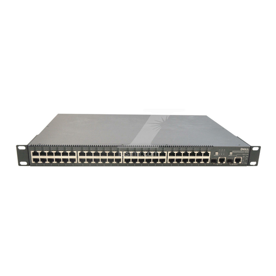
Page 226: Hardware Description
Back to Contents Page Hardware Description Dell™ PowerConnect™ 3324/3348 User's Guide PowerConnect 3324/3348 Description Ports Description LED Definitions PowerConnect 3324/3348 Description PowerConnect 3324/3348 Dimensions This device has the following dimensions: Width—19" Height—1U PowerConnect 3324/3348 Rear Panel The rear panel of the Dell™ PowerConnect™ 3324/3348 is shown in the following figure: ... -
Page 227: Mode Button
CPU—Based on Motorola's MPC 8245. FLASH—Contains 8 MB of FLASH Memory. SDRAM—Contains 32 MB. PowerConnect 3324 Front Panel PowerConnect 3348 Front Panel Mode Button The Mode Button toggles between port activity and port duplex settings. Stack ID Button ... -
Page 228: Ethernet Port Description
Stacking Connections For more information about connecting Stacking cables, see "Connecting Stacking Cables". Ports Description Ethernet Port Description The PowerConnect 3324 features 24 FE 10BaseT/100BaseTX UTP copper RJ45 ports per unit and 2 combo ports. The PowerConnect 3348 features 48 FE 10BaseT/100BaseTX UTP copper RJ45 ports per unit and 2 combo ports. -
Page 229: Console Port Description
Console Port Description The console port interface supports synchronous data of eight data bits, one stop bit, and no parity. All RS232 pins are supported (9 pins) for Modem support. LED Definitions The front panel LEDs in the following figures indicate the status of port links and modes, power supply status, stacking status, and system diagnostics. The LED types are as follows: Port LEDs System LEDs... -
Page 230: System Leds
Red Static Port link up. Port operating at 10 Mbps. Red Flashing Port link up with activity. Port operating at 10 Mbps. Off Off Port link down. Port Link Activity Color Activity Definition Green Static Port full duplex. Off Off Port link down or half duplex. - Page 231 The stacking LEDs indicate the unit's position in the stack. As shown in the front panel illustrations at the start of this section, the stacking LEDs are numbered 1 through 6. Each unit in the stack has one stacking LED lit, indicating its position in the stack. When stacking LED 1 is lit, the unit is the master unit. When one of the stacking LEDs numbered 2 through 6 is lit, the unit is the corresponding stacking member unit.
-
Page 232: Installation Precautions
Site Requirements Dell™ PowerConnect™ 3324/3348 series equipment can be mounted in a standard 19-inch equipment rack or placed on a table. Before installing the unit, verify that the location chosen for installation meets the site requirements described below. General—Ensure that the power supply is correctly installed. Power—The unit is installed within 1.5 m (5 feet) of a grounded, easily accessible outlet 100-250 VAC, 50-60 Hz. It is preferred that two separate power supplies are provided, for example, a UPS and a separated phased supply. -
Page 233: Package Contents
4. Carefully remove the unit from the container and place it on a secure and clean surface. 5. Remove all packing material. 6. Inspect the product for damage. Report any damage immediately. For information about contacting Dell, see "Getting Help". -
Page 234: Connecting Stacking Cables
PowerConnect 3324/3348 stack contains a single Master unit, while the remaining units are considered stacking members. All management is done through the Master unit. Both 24-port and 48-port devices can be included in the stack. To enable stacking, units must be stacked with a Stack Module connected to port G2 in the SFP slot. ... -
Page 235: Ac Power Connection
The following section contains instruction for connecting the PowerConnect 3324/3348 to a AC power connection. The PowerConnect 3324/3348 is supplied with power from: AC power supply source. An optional PowerConnect RPS-600 redundant power supply. Both AC and DC sources. Connecting PowerConnect 3324/3348 to a Power Supply Plug in the PowerConnect 3324/3348 to one of the previously listed power sources. -
Page 236: Port Connections
This section describes the PowerConnect 3324/3348 physical interfaces and provides information about cable connections. Stations are connected to PowerConnect 3324/3348 ports through the physical interface ports on the front panel. For each station, the appropriate mode (Half/Full Duplex, Auto) is set. ... -
Page 237: Cable Connections
GigaPort Connector A serial cable connects PowerConnect 3324/3348 to a terminal for the initial setup and configuration. (A PC running terminal emulation software can also be used.) The serial cable is a female-to-female DB-9 crossover cable. The following figure illustrates the DB-9 connector. ... - Page 238 The serial port connector is a DB-9 type connector. A supplied interface cable is required to connect the device. To connect the device: 1. Connect the interface crossed cable to the terminal ASCII DTE RS-232 connection. 2. Connect the interface crossed cable to the device serial connection. ...
-
Page 239: System Description
Back to Contents Page Overview Dell™ PowerConnect™ 3324/3348 User's Guide System Description PowerConnect 3324/3348 Stacking Overview PowerConnect User Guide Overview PowerConnect 3324/3348 CLI Documentation System Description The Dell™ PowerConnect™ 3324 and 3348 devices are standalone and stackable advanced Layer 2 switches. PowerConnect 3324 and PowerConnect 3348 also function as stand-alone Layer 2 switching systems. PowerConnect 3324/3348 devices are managed either using In-Band Management (via the network station remotely) or via the console. -
Page 240: Stack Members And Unit Id
Trunking Port Mirroring VLANs For example, VLANs can be configured from ports belonging to different stack members, or configure port mirroring from a second stack member to a third stack member. Applications running in a stacking configuration are centralized. For example, the Spanning Tree Protocol for the entire stack runs on the master unit. -
Page 241: Rearranging Stacks
Only ports that are physically present are displayed in the Dell OpenManage™ Switch Administrator and can be configured through the web management system. Non-present ports are configured through the CLI or SNMP interfaces. Rearranging Stacks The stacking order can be changed by either removing a stack member or by rearranging the stacking cables. The order in which stack members are arranged is established not by the physical order of the stack members but by the Unit ID assignment. -
Page 242: Using The Dell Openmanage Switch Administrator
Statistics—Contains information about viewing table and chart statistics for ports, GVRP, Etherlike, RMON, and interface statistics. Configuring Quality of Service—Contains information about configuring device Class of Service. Getting Help—Contains information about technical assistance, problems with your order, returning items for repair or credit, and how to contact Dell. PowerConnect 3324/3348 CLI Documentation ... -
Page 243: Viewing Statistics
Back to Contents Page Viewing Statistics Dell™ PowerConnect™ 3324/3348 User's Guide Viewing Tables Viewing RMON Information Viewing Charts The Statistic pages contains device information for interface, GVRP, etherlike, RMON, and device utilization. To open the Statistics/RMON page: Click Statistics/RMON in the Tree View. The Statistics/RMON page opens. -
Page 244: Viewing Utilization Summary
Table View Page The Table View page contains the following links: Viewing Utilization Summary Viewing Counter Summary Viewing Interface Statistics Viewing Etherlike Statistics Viewing GVRP Statistics Viewing Utilization Summary The Utilization Summary page contains statistics for port utilization. To open the Utilization Summary page: Click Statistics >... -
Page 245: Viewing Counter Summary
Utilization Summary Page The Utilization Summary page contains the following fields: Unit No.—Indicates the unit number for which port statistics are displayed. Port—Indicates the port number. Port Status—Indicates the port status. % Port Utilization—Indicates the port utilization. % Unicast Received—Indicates the percentage of Unicast packets received on the ports. % Non Unicast Received—Indicates the number of bad packets received on the port % Error Packets Received—Indicates the number packets with errors received on the port. -
Page 246: Viewing Interface Statistics
Counter Summary Page The Counter Summary page contains the following fields: Unit No.—Indicates the unit number for which port statistics are displayed. Port—Indicates the port number. Port Status—Indicates the port status. Received Unicast Packets—Indicates the number of received Unicast packets on the port. Transmit Unicast Packets—Indicates the number of transmitted Unicast packets from the port. - Page 247 Interface Statistics Page The Interface Statistics page contains the following fields: Interface—Specifies the interface (type and number) for which the statistics are displayed. Port—Indicates port statistics are displayed. ¡ LAG—Indicates LAG statistics are displayed. ¡ Refresh Rate—Indicates the amount of time that passes before the interface statistics are refreshed. The possible field values are: 15 Sec—Indicates that the interface statistics are refreshed every 15 seconds.
-
Page 248: Viewing Interface Statistics Using The Cli Commands
Displaying interface statistics for a port: 1. Open the Interface Statistics page. 2. Select Port in the Interface field. 3. Click Reset All Counters. The port interface statistics are displayed. Displaying interface statistics for a LAG: 1. Open the Interface Statistics page. 2. -
Page 249: Viewing Etherlike Statistics
Multiple Collision Frames: 0 Deferred Transmissions: 0 Late Collisions: 0 Excessive Collisions: 0 Internal MAC Tx Errors: 0 Carrier Sense Errors: 0 Oversize Packets: 0 Internal MAC Rx Errors: 0 Symbol Errors: 0 ... - Page 250 Etherlike Statistics Page The Etherlike Statistics page contains the following fields: Interface—Specifies the interface type for which the statistics are displayed. Port—Indicates port statistics are displayed. ¡ LAG—Indicates LAG statistics are displayed. ¡ Refresh Rate—Indicates the amount of time that passes before the interface statistics are refreshed. The possible field values are: 15 Sec—Indicates that the Etherlike statistics are refreshed every 15 seconds.
-
Page 251: Viewing Gvrp Statistics
Displaying Etherlike statistics for a port: 1. Open the Etherlike Statistics page. 2. Select Port in the Interface field. 3. Click Query. The port Etherlike statistics are displayed. Displaying Etherlike statistics for a LAG: 1. Open the Etherlike Statistics page. 2. -
Page 252: Viewing Gvrp Statistics Using The Cli Commands
15 Sec—Indicates that the GVRP statistics are refreshed every 15 seconds. ¡ 30 Sec—Indicates that the GVRP statistics are refreshed every 30 seconds. ¡ 60 Sec—Indicates that the GVRP statistics are refreshed every 60 seconds. ¡ No Refresh—Indicates that the GVRP statistics are not automatically refreshed. ¡... -
Page 253: Viewing Rmon Information
Legend: rJE: Join Empty Received . : Join In Received rEmp : Empty Received rLIn : Leave In Received rLE : Leave Empty Received rLA : Leave All Received sJE : Join Empty Sent sJIn : Join In Sent ... -
Page 254: Viewing Rmon Statistics
RMON Page This section contains the following topics: Viewing RMON Statistics Viewing History Control Statistics Viewing The RMON History Table Defining Device Events Viewing the Events Log Defining Device Alarms Viewing RMON Statistics The RMON Statistics Group page allows network managers to display RMON statistics for an interface. Interface statistic provide information about device utilization, and errors that occurred on the device. - Page 255 RMON Statistics Group Page The RMON Statistics Group page contains the following information: Interface—Indicates the interface type and number for which statistics are displayed. The possible field values are: Port—Indicates that port specific statistics are displayed. ¡ LAG—Indicates that LAG specific statistics are displayed. ¡...
-
Page 256: Viewing History Control Statistics
Frames of 256-511 Bytes—Indicates the amount of 256-511 byte packets received on the interface since the counters were last cleared. Frames of 512-1023 Bytes—Indicates the amount of 512-1023 byte packets received on the interface since the counters were last cleared. Frames of 1024-1518 Bytes—Indicates the amount of 1024-1518 byte packets received on the interface since the counters were last cleared. - Page 257 Click Statistics/RMON > History Control in the Tree View. The RMON History Control page opens. RMON History Control Page The RMON History Control page contains the following information: History Entry No.—Specifies the History Control Table entry. Source Interface—Indicates the source from which the history samples were taken. The possible field values are: Port—Indicates the history samples were taken from a port.
-
Page 258: Viewing The Rmon History Table
Add History Entry 3. Define the History Entry No., Source Interface, Owner, Max No. of Samples to Keep, and the Sampling Interval fields. 4. Click Apply Changes. The History Control Entry is added. Modifying a History Control Table entry: 1. - Page 259 RMON History Table NOTE: Not all fields are shown in the RMON History Table. The RMON History Table contains the following fields: Sample No.—Indicates the specific sample that the information in the table reflects. Drop Events—Indicates the number of dropped packets due to lack of network resources during the sampling interval. This may not represent the exact number of dropped packets, but rather the number of times dropped packets were detected.
- Page 260 The following table contains the CLI commands for viewing RMON history statistics. CLI Command Description rmon table-size history entries Configures the maximum number of history table entries. rmon collection history index [owner ownername] [buckets bucket-number] Enables a Remote Monitoring (RMON) MIB history statistics group on an interface.
-
Page 261: Defining Device Events
Time Octets Packets Broadcast Multicast Utilization ---- ------ ------- --------- --------- ----------- 00:00:00 287696304 275686 2789 5878 20.17% 00:00:30 303595962 357568 3289 7287 19.98% Defining Device Events The RMON Events Control page allows network managers to view RMON events. The RMON Events table can be opened from the RMON Events Control table. - Page 262 Log—Indicates the event type is a log entry. ¡ Trap—Indicates the event type is a trap. ¡ Log and Trap—Indicates the event type is both a log entry and a trap. ¡ Time— Indicates the time at which the event occurred. Owner—Indicates the device or user that defined the event.
-
Page 263: Viewing The Events Log
2. Select an Event Table entry in the Event Index field. 3. Check the Remove check box. 4. Click Apply Changes. The Event Table entry is deleted, and the device is updated. NOTE: A single Event entry can be removed from the RMON Events page using the Remove check box. ... - Page 264 RMON Events Log Page The RMON Events Log page contains the following fields: Event—Identifies the RMON Event Log entry number. Log No.— Indicates the log number. Log Time—Specifies the time at which the log entry was entered. Description—Describes the log entry. ...
-
Page 265: Defining Device Alarms
Maximum table size: 500 Event Description Time ----- ----------- -------------------- 1 Errors Jan 18 2002 23:48:19 1 Errors Jan 18 2002 23:58:17 2 High Broadcast Jan 18 2002 23:59:48 Console# show rmon log ... - Page 266 RMON Alarm Page The RMON Alarm page contains the following fields: Alarm Entry—Indicates a specific alarm. Counter Name—Indicates the selected RMON counter. Counter Value—Indicates the value of the RMON counter. Sample Type—Specifies the sampling method for the selected variable and compares the value against the thresholds. The possible field values are: Delta—Subtracts the last sampled value from the current value.
- Page 267 Adding an Alarm Table entry: 1. Open the RMON Alarm page. 2. Click Add. The New Alarm Entry page opens. New Alarm Entry 3. Define the New Alarm Index, Sample Variable, Sample Type, Rising Threshold, Rising Event, Falling Threshold, Falling Event, Startup Alarm, Interval, and Owner fields.
- Page 268 CLI Command Description rmon alarm index variable interval rthreshold fthreshold revent fevent [type type] [startup direction] [owner Configures alarm conditions. name] show rmon alarm-table Displays the alarm summary table. show rmon alarm number Displays alarm configurations. The following is an example of the CLI command: ...
-
Page 269: Viewing Charts
Falling Threshold: 78 Rising Event: 1 Falling Event: 1 Owner: CLI Viewing Charts The Charts page contains links for displaying statistics in a chart form. To open the Charts page: Click Statistics > Charts in the Tree View. The Charts page opens. ... -
Page 270: Viewing Port Statistics
Viewing Port Statistics The Ports page displays statistics in a chart form for a selected port. To open the Port Statistics page: Click Statistics > Charts > Ports in the Tree View. The Port Statistics page opens. Port Statistics Page ... - Page 271 The following table summarizes the equivalent CLI commands for viewing fields displayed on the Port Statistics page. CLI Command Description clear counters [ethernet interface | port-channel port-channel-number] Clears statistics on an interface. show rmon statistics [ethernet interface | port-channel port-channel-number] Displays RMON ethernet Statistics.
- Page 272 GVRP statistics: ---------------- Legend: rJE : Join Empty Received rJIn : Join In Received rEmp : Empty Received rLIn : Leave In Received rLE : Leave Empty Received rLA : Leave All Received sJE : Join Empty Sent sJIn : Join In Sent ...
-
Page 273: Viewing Lag Statistics
GVRP error statistics: ---------------- Legend: INVPROT : Invalid Protocol Id INVPLEN : Invalid PDU Length INVATYP : Invalid Attribute Type INVALEN : Invalid Attribute Length INVAVAL : Invalid Attribute Value INVEVENT : Invalid Event ... - Page 274 LAG Statistics Page The LAG Statistics page contains the following fields: Interface Statistics—Provides interface statistics for trunks. Etherlike Statistics—Provides Etherlike statistics for trunks. RMON Statistics—Provides RMON statistics for trunks. GVRP Statistics—Provides GVRP statistics for trunks. Refresh Rate—Specifies the amount of time that passes before the device is refreshed. The possible field values are: 15 Sec—Indicates that the LAG statistics are refreshed every 15 seconds.
- Page 275 CLI Command Description show interfaces counters [ ethernet interface | port-channel port-channel-number] Displays statistics for a physical interface. The following is an example of the CLI commands: Console# show interfaces counters Port InOctets InUcastPkts InMcastPkts InBcastPkts ...
- Page 276 Console# show interfaces counters ethernet 1/e1 Port InOctets InUcastPkts InMcastPkts InBcastPkts ---- ---------- --------- --------- ------------ 1/e1 183892 1289 987 8 Port OutOctets OutUcastPkts OutMcastPkts OutBcastPkts ---- ---------- --------- --------- ------------ 1/e1 9188 9 8 0 ...
- Page 277 Transmitted Pause Frames: 0 ---------------------------------------------------------------------------------------- Back to Contents Page ...
-
Page 278: Notes, Notices, And Cautions
Latitude are trademarks of Dell Inc.; Microsoft and Windows are registered trademarks of Microsoft Corporation. Other trademarks and trade names may be used in this document to refer to either the entities claiming the marks and names or their products. Dell Inc. disclaims any proprietary interest in trademarks and trade names other than its own.