
Related Manuals for Dell PowerConnect 3324


Summary of Contents for Dell PowerConnect 3324
- Page 1 Dell™ PowerConnect™ 3324/3348 User’s Guide Model PowerConnect 3324/3348 w w w . d e l l . c o m | s u p p o r t . d e l l . c o m...
- Page 2 Other trademarks and trade names may be used in this document to refer to either the entities claiming the marks and names or their products. Dell Inc. disclaims any proprietary interest in trademarks and trade names other than its own.
-
Page 3: Table Of Contents
Stack Members and Unit ID Configuration Handling Rearranging Stacks Replacing Stack Members PowerConnect User Guide Overview Installing the PowerConnect 3324/3348 Switch Using the Dell OpenManage Switch Administrator PowerConnect 3324/3348 CLI Documentation 2 Hardware Description PowerConnect 3324/3348 Description PowerConnect 3324/3348 Dimensions... - Page 4 3 Installing the PowerConnect 3324/3348 Switch Installation Precautions Site Requirements Unpacking and Installation Package Contents ......
- Page 5 Downloading the Software Individually Using the CLI Downloading the Software Via the PowerConnect 3324/3348 Dell OpenManage Switch ......
- Page 6 ......Tree View Device View Device Representation Using the Switch Administrator Buttons Information Buttons About PageDevice Management Buttons Using the CLI .
- Page 7 Managing Logs ......Defining Global Log Parameters ....Displaying RAM Log Table Displaying the Log File Table Displaying the Log File Table Using the CLI Commands...
- Page 8 7 Configuring Switch Information Configuring Network Security Network Security Overview Configuring Port Security Defining IP-Based ACLs Defining MAC-Based ACLs Binding ACLs Configuring Ports Defining Port Parameters Defining LAG Parameters Enabling Storm Control Defining Port Mirroring Sessions Configuring Address Tables Defining Static Addresses...
- Page 9 Multicast Forwarding Support Defining IGMP Snooping Settings Adding Bridge Multicast Group Members Assigning Multicast Forward All Parameters Enabling IGMP Snooping 8 Viewing Statistics Viewing Tables ......Viewing Utilization Summary Viewing Counter Summary Viewing Interface Statistics...
- Page 10 Mapping UDP Port Values to Queues 10 Getting Help Technical Assistance Online Services AutoTech Service Automated Order-Status Service Technical Support Service Dell Enterprise Training and Certification Problems With Your Order Product Information Returning Items for Warranty Repair or Credit Before You Call Contacting Dell Contents .
-
Page 11: Overview
S E C T I O N 1 O v e r v i e w System Description PowerConnect 3324/3348 Stacking Overview PowerConnect User Guide Overview PowerConnect 3324/3348 CLI Documentation... -
Page 12: System Description
SNMP management and a console/telnet session through which the entire stack is managed. PowerConnect 3324/3348 supports stacking up to six units per stack or scale up to 192 FE and six Gigabit Ethernet ports. PowerConnect 3324/3348 can also operate as standalone units. -
Page 13: Stack Members And Unit Id
If a PowerConnect 3324/3348 unit is operating as a stand-alone unit, all stacking LEDs are off. The Unit ID is not erased and remains valid if the unit is reconnected to a stack. -
Page 14: Configuration Handling
Configuration Handling In a PowerConnect 3324/3348 operative stack, the stack master is responsible for the stack configuration. Each stack member does not have a separate configuration file. Each port in the stack has a specific Unit ID/port type and port number, which is part of both the configuration commands and the configuration files. -
Page 15: Rearranging Stacks
Unit ID assignment. The stack configuration is stored in stack master after the stack order is changed, and the stack is reset. If the PowerConnect 3324/3348 unit is removed or replaced in a stack, the stack recovers from the disconnection as follows: •... - Page 16 48 10/100 BaseT port configuration. Ports G1 and G2 receive the previous device’s G1 and G2 port configuration. • If a PowerConnect 3348 replaces PowerConnect 3324, then ports 1-24 10/100 BaseT receive the previous device’s configuration for ports 1-24. •...
-
Page 17: Powerconnect User Guide Overview
LED types. • Installing the PowerConnect 3324/3348 installing PowerConnect 3324/3348 in either a rack or on a flat surface. In addition, this section contains installation precautions, and a description of the connectors and cables. -
Page 18: Powerconnect 3324/3348 Cli Documentation
Dell. PowerConnect 3324/3348 CLI Documentation In addition to the PowerConnect 3324/3348 User Guide, Dell provides the PowerConnect 3324/3348 CLI Reference Guide. The PowerConnect 3324/3348 CLI Reference Guide provides information about the CLI commands used to configure the PowerConnect 3324/3348. -
Page 19: Hardware Description
S E C T I O N 2 H a r d w a r e D e s c r i p t i o n PowerConnect 3324/3348 Description Ports Description LED Definitions... -
Page 20: Powerconnect 3324/3348 Description
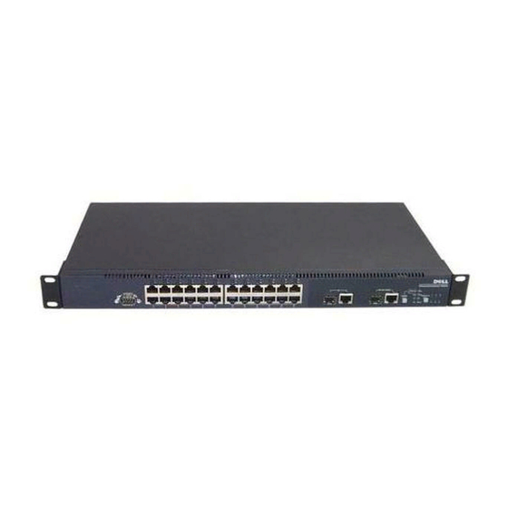
PowerConnect 3324/3348 Rear Panel The rear panel of the Dell™ PowerConnect™ 3324/3348 is shown in the following figure: P o w e r C o n n e c t 3 3 2 4 R e a r P a n e l... -
Page 21: Stacking Leds
General Device Components The PowerConnect 3324/3348 includes the following hardware components: • CPU—Based on Motorola’s MPC 8245. • FLASH—Contains 8 MB of FLASH Memory. • SDRAM—Contains 32 MB. Stack ID Button P o w e r C o n n e c t 3 3 2 4 F r o n t P a n e l... - Page 22 The Mode Button toggles between port activity and port duplex settings. Stack ID Button The PowerConnect 3324/3348 front panel contains a Stack ID button that permits network administrators to manually select the Stack Master and stack members. NOTE: The Stack Master and stack members must be selected within 15 seconds after booting the device.
- Page 23 Master Unit Member Unit Member Unit Member Unit S t a c k i n g C o n n e c t i o n s For more information about connecting Stacking cables, see "Connecting Stacking Cables". H a r d w a r e D e s c r i p t i o n...
-
Page 24: Ports Description
Only one of the two physical connections of a combo port may be used at any one time. If auto-MDIX is enabled, PowerConnect 3324/3348 automatically detects and corrects the difference between crossover and straight-through cables on all ports. PowerConnect 3324/3348 supports half and full duplex mode 10/100 M bps speed for copper ports. Console Port Description The console port interface supports synchronous data of eight data bits, one stop bit, and no parity. -
Page 25: System Leds
F r o n t P a n e l L E D s : 2 4 P o r t s Mode Button F r o n t P a n e l L E D s : 4 8 P o r t s System LEDs Link/Act Duplex... -
Page 26: Port Leds
Port LEDs Each port has one corresponding LED located above the port. The LEDs show either link activity or duplex mode, depending on the port LED display mode. For information about setting the LED display mode, see Color Green Green P o r t L i n k A c t i v i t y Color Green... - Page 27 Color Activity Green Static Green Flashing Static Flashing G i g a P o r t L i n k A c t i v i t y S t a t u s • The Mode button located next to the system LEDs is used to toggle between the two display modes.
-
Page 28: Stacking Leds
Stacking LEDs The stacking LEDs indicate the unit’s position in the stack. As shown in the front panel illustrations at the start of this section, the stacking LEDs are numbered 1 through 6. Each unit in the stack has one stacking LED lit, indicating its position in the stack. When stacking LED 1 is lit, the unit is the master unit. -
Page 29: Installing The Powerconnect 3324/3348 Switch
S E C T I O N 3 I n s t a l l i n g t h e P o w e r C o n n e c t 3 3 2 4 / 3 3 4 8 S w i t c h Installation Precautions Site Requirements Unpacking and Installation... -
Page 30: Installation Precautions
NOTICE: Ensure the air flow around the front, sides, and back of the switch is not restricted. Site Requirements Dell™ PowerConnect™ 3324/3348 series equipment can be mounted in a standard 19-inch equipment rack or placed on a table. Before installing the unit, verify that the location chosen for installation meets the site requirements described below. -
Page 31: Unpacking And Installation
Rack mount kits for rack installation. • Documentation CD. Unpacking NOTE: Before unpacking the PowerConnect 3324/3348 switch, inspect the package and report any evidence of damage immediately. Ground yourself by putting on an ESD wrist strap and attaching the ESD clip to a metal surface. -
Page 32: Device Rack Installation
Installing the Switch without a Rack The PowerConnect 3324/3348 must be installed on a flat surface if it is not installed on a rack. The surface must be able to support the weight of the device and the device cables. -
Page 33: Stacking Powerconnect 3324/3348
Stacking PowerConnect 3324/3348 PowerConnect 3324/3348 supports stacking up to six PowerConnect up to 192 Fast Ethernet ports and six Giga ports. Each PowerConnect contains a single Master unit, while the remaining units are considered stacking members. All management is done through the Master unit. Both 24-port and 48-port devices can be included in the stack. -
Page 34: Connecting The Powerconnect 3324/3348 To A Power Supply
C o n n e c t e d S t a c k For more information on configuring stacks, see Connecting the PowerConnect 3324/3348 to a Power Supply The following section contains instruction for connecting the PowerConnect 3324/3348 to a AC power connection. The PowerConnect 3324/3348 is supplied with power from: •... -
Page 35: Cable, Port, And Pinout Information
C o n n e c t i n g P o w e r C o n n e c t 3 3 2 4 / 3 3 4 8 t o a P o w e r S u p p l y • Plug in the PowerConnect 3324/3348 to one of the previously listed power sources. AC Power Connection AC power should be supplied to the unit through a 1.5m (5 foot) standard power cable with... -
Page 36: Port Connections
Port Connections The ports are all standard RJ45 Ethernet ports. Switching ports can connect to stations wired in standard RJ45 Ethernet station mode using straight cables. Transmission devices use crossed cables to connect to each other. The following figure illustrates the RJ45 pin number allocations for the 10/100M ports. R J 4 5 P i n N u m b e r A l l o c a t i o n RX + RX -... - Page 37 G i g a P o r t C o n n e c t o r A serial cable connects PowerConnect 3324/3348 to a terminal for the initial setup and configuration. (A PC running terminal emulation software can also be used.) The serial cable is a female-to-female DB-9 crossover cable.
-
Page 38: Cable Connections
D B - 9 P i n N u m b e r A l l o c a t i o n Cable Connections This section describes how to connect the various cables to the PowerConnect 3324/3348 device. I n s t a llin g t h e Po we r C o n n e c t 3 324 / 33 48 Sw i t c h... - Page 39 ASCII Terminal (Serial) Connection The serial port connector is a DB-9 type connector. A supplied interface cable is required to connect the device. To connect the device: Connect the interface crossed cable to the terminal ASCII DTE RS-232 connection. Connect the interface crossed cable to the device serial connection. P o w e r C o n n e c t 3 3 2 4 Te r m i n a l C o n n e c t i o n I n s t a l l i n g t h e Po w e r C o n n e c t 3 3 2 4 / 3 3 4 8 S w i t c h...
- Page 40 P o w e r C o n n e c t 3 3 4 8 Te r m i n a l C o n n e c t i o n I n s t a llin g t h e Po we r C o n n e c t 3 324 / 33 48 Sw i t c h...
-
Page 41: Configuring The Powerconnect 3324/3348 Switch
S E C T I O N 4 C o n f i g u r i n g t h e P o w e r C o n n e c t 3 3 2 4 / 3 3 4 8 S w i t c h Configuration Overview General Configuration Information Terminal Connection Configuration... -
Page 42: Configuration Overview
Configuration Overview This section describes the initial device configuration and includes: • Initial Device Bootup • Preliminary Configuration Requirements • Configuring Stacking After all the device external connections are in place, a terminal must be connected to the device to monitor the boot and other procedures. The order of installation and configuration procedures are illustrated in the following flowchart: C o n f i g u r i n g t h e Po w e r C o n n e c t 3 3 2 4 / 3 3 4 8 S w i t c h... -
Page 43: General Configuration Information
This option is described later in this section. General Configuration Information Dell™ PowerConnect™ 3324/3348 is provided with pre-defined implemented features and setup configuration. Auto-Negotiation Auto-negotiation allows a device to advertise modes of operation and share information with another device that shares a point-to-point link segment. -
Page 44: Switching Port Default Settings
Switching Port Default Settings The following table describes the Port default settings. P o r t D e f a u l t S e t t i n g s Function Port speed and mode Port forwarding state Port tagging Head of line blocking prevention Flow Control Back Pressure... -
Page 45: Baud Rate
9600 console(config-if)# exit console(config)# exit Terminal Connection Configuration The PowerConnect 3324/3348 requires the following Terminal Connection parameters for configuration: • no parity • one stop bit • 8 data bits... -
Page 46: Other Configuration Requirements
• ASCII terminal (or emulation) connected to the Serial port in the back of the unit. • Assigned IP address for PowerConnect 3324/3348 for device remote control using with Telnet, SSH, etc. NOTE: The configuration process defines only one port. - Page 47 BOOT Software Version 1.30.11 Built 27-JAN-2003 10:06:03 Processor: MPC8245 Rev 0.12, 250 MHz (Bus: 100MHz), 32 MByte SDRAM. I-Cache 16 KB, linesize 32.D-Cache 16 KB, linesize 32. Cache Enabled. Autoboot in 2 seconds - press RETURN or Esc. to abort and enter prom.
-
Page 48: Device Configuration Introduction
STAND ALONE The BCM5625_A1 0 initiate successfully The BCM5625_A1 1 initiate successfully 02-Jan-2000 01:01:11%SSHD-W-NOHOSTKEY: SSHG_init: The SSH daemon cannot listen for incoming connections, because a host key has not been generated. The service will start automatically when a host key is generated. 01-Jan-2000 01:01:11 %INIT-I-InitCompleted: Initialization task is completed console>... -
Page 49: Initial Configuration
Static IP Address and Subnet Mask In PowerConnect 3324/3348 devices, IP interfaces can be configured on each port and no limitation on the number of IP interfaces is imposed. After entering the configuration command, it is recommended to check if a port was configured with the IP address by entering the "show ip interface"... - Page 50 Gateway IP Address ----------------------- ----------------------- IP Address ----------------------- ---------------------- 100.1.1.1/8 console# To configure an interface on a port, enter the commands at the system prompt as shown in the following configuration example: console> enable console# configure console(config)# interface ethernet 1/e1 console(config-if)# ip address 10.1.1.1 255.0.0.0 console(config-if)# exit console(config)# exit...
-
Page 51: Default Gateway
Default Gateway To manage a PowerConnect 3324/3348 device from a remote network, a default gateway, which is the gateway that a device uses if a specific gateway is not specified, must be configured. The configured gateway IP address must belong to the same subnet as one of the device IP interfaces. - Page 52 The device is SNMP-compliant. It contains an SNMP agent that supports a set of standard and private MIB variables. Developers of management stations require the exact structure of the MIB tree and receive the complete private MIBs information before being able to manage the MIBs.
-
Page 53: Advanced Configuration
To configure SNMP station IP address and community string(s): At the console prompt, type Enable. The prompt is displayed as #. Type configure and press <Enter>. In the configuration mode, type the SNMP configuration command with the parameters including community name (private), community access right (read and write) and IP address, as shown in the example below: console>... -
Page 54: Retrieving An Ip Address From A Dhcp Server
When configuring/receiving IP addresses through DHCP and BOOTP , the configuration received from these servers includes IP address, and may include subnet mask and default gateway. Retrieving an IP address from a DHCP Server When using the DHCP protocol to retrieve an IP address, the device acts as a DHCP client. To retrieve an IP address from a DHCP server: Select and connect any port to a DHCP server or to a subnet which has a DHCP server on it, in order to retrieve the IP address. -
Page 55: Receiving An Ip Address From A Bootp Server
console# NOTE: The device configuration does not need to be deleted to retrieve an IP address for the DHCP server. Receiving an IP address from a BOOTP Server The standard BOOTP protocol is supported enabling the device to automatically download their IP host configuration from any standard BOOTP server in the internet. -
Page 56: Security Management And Password Configuration
To verify the IP address, see the following display example. console> enable console# show ip interface Gateway IP Address ----------------------- ----------------------- IP Address ----------------------- ---------------------- 10.1.1.1/8 console# Now the device is configured with an IP address. The device configuration must be deleted to retrieve an IP address from the BOOTP server. Security Management and Password Configuration System security is handled through the AAA (Authentication, Authorization and Accounting) mechanism that manages user access rights, privileges and management... -
Page 57: Configuring Security Passwords
Configuring Security Passwords The security passwords can be configured for the following services: • Console • Telnet • • HTTP • HTTPS NOTE: Passwords are user-defined. NOTE: When creating a user name, the default priority is "1", which allows access but not configuration rights. - Page 58 Configuring an Initial Telnet Password To configure an initial Telnet password, enter the following commands: console> enable console# configure console(config)# aaa authentication login default line console(config)# aaa authentication enable default line console(config)# line telnet console(config-line)# login authentication default console(config-line)# enable authentication default console(config-line)# password admin console(config-line)# exit console(config)# exit...
- Page 59 Configuring an Initial HTTP Password To configure an initial HTTP password, enter the following commands: console> enable console# configure console(config)# ip http authentication local console(config)# username admin password admin level 15 console(config)# exit Configuring an Initial HTTPS Password To configure an initial HTTPS password, enter the following commands: console>...
-
Page 60: Sample Configuration Process
Straight or cross UTP (cat 5) cable(s) Initial Connection The initial connection is as follows: Connect the PowerConnect 3324/3348 device to the RS232 interface of a computer operating as an ASCII terminal. Set the ASCII terminal with the following settings and select the appropriate COM... - Page 61 NOTE: 9600 is the default baud rate for new device. If using 9600 baud rate does not result in viewing the device terminal, try another baud rate setting (the device may be set at a different baud rate). Use an F2F Null Modem cable to connect the PC running the ASCII terminal to the device.
- Page 62 Booting... ------ Performing the Power-On Self Test (POST( ------ UART Channel Loopback Test...PASS Testing the System Cache...PASS Testing the System SDRAM...PASS Boot1 Checksum Test...PASS Boot2 Checksum Test...PASS Flash Image Validation Test...PASS Testing CPU PCI Bus Device Configuration...PASS BOOT Software Version 1.0.0.13 Built 11-May-2003 14:58:20 Processor: MPC8245 Rev 0.14, 250 MHz (Bus: 100MHz), 32 MByte SDRAM.
- Page 63 ****************************************************************** *** Running Ver. 1.0.0.52 ****************************************************************** HW version is 00.00.01 Base Mac address is: 00:06:5b:ff:59:4d Dram size is : 32M bytes Dram first block size is Dram first PTR is : 0xB20000 Flash size is: 8M STAND ALONE The BCM5615_A1 0 initiate successfully 01-Jan-2000 01:01:10 %SSHD-W-NOHOSTKEY: SSH has been enabled but an encryption key was not found.
-
Page 64: Device Default Settings
Jan-2000 01:01:13 %LINK-W-Down: 01-Jan-2000 01:01:13 %LINK-W-Down: 01-Jan-2000 01:01:13 %LINK-W-Down: 01-Jan-2000 01:01:13 %LINK-W-Down: 01-Jan-2000 01:01:13 %LINK-W-Down: 01-Jan-2000 01:01:14 %LINK-I-Up: 01-Jan-2000 01:01:14 %LINK-I-Up: console> The device is ready for configuration. Device Default Settings To return to device default settings use delete startup-config command at the privileged mode prompt (#), and reboot the device. -
Page 65: Remote Management Access
************************************************** ***************** SYSTEM RESET ************************************************** Remote Management Access To allow remote device management (Telnet, Web etc.) perform the following: Enter the command enable at the console to enter the Privileged EXEC screen mode as follows: console>enable console# Connect the management station (PC) to the device via one of the Ethernet ports (or via a network connected to the device) using a CAT5 Cable, to port e1 in this example. - Page 66 Enter the command interface ethernet at the console to enter the Device Configuration screen mode through VLAN1 as follows: console> enable console# configure console(config)# interface vlan 1 console (config)# exit Define an IP address on the device by assigning an IP address to the interface connected to the management station (in this example 50.1.1.1).
- Page 67 (telnet, Web Server etc.). In this example the username and password is "Dell". console# console# configure console(config)# username Dell password Dell level 15 console(config)# Configure Console, Telnet, SSH, HTTP , and HTTPS security passwords: console> enable console# configure...
-
Page 68: Start Running The Management Station
console(config)# line telnet console(config-line)# login authentication default console(config-line)# enable authentication default console(config-line)# password admin console(config-line)# exit console(config)# aaa authentication login default line console(config)# aaa authentication enable default line console(config)# line ssh console(config-line)# login authentication default console(config-line)# enable authentication default console(config-line)# password admin console(config-line)# exit console(config)# ip http authentication local console(config)# username admin password admin 15... - Page 69 Select the option to configure the internet protocol (TCP/IP) and click Properties. The Internet Protocol (TCP/IP) properties window is displayed. C o n f i g u r i n g t h e Po w e r C o n n e c t 3 3 2 4 / 3 3 4 8 S w i t c h...
-
Page 70: Telnet Access
DHCP) an IP address, Mask and default gateway for the PC. NOTE: If the PC is connected to a router and not directly to PowerConnect 3324/3348 device, the default gateway must be configured as the IP address of the router interface connected to the PC (which leads to the PowerConnect device). - Page 71 Enter the command Telnet and the device IP address. Microsoft Windows 2000 [Version 5.00.2195] (C) Copyright 1985-2000 Microsoft Corp. C:\>telnet 50.1.1.2 01-Jan-2000 02:40:23 %MSCM-I-NEWTERM: New TELNET connection from 50.1.1.2 User Name:Dell Password:**** console# show ip interface Gateway IP Address ----------------------- ----------------------- 50.1.1.100...
-
Page 72: Web Access (Http Server)
Notice that Device indicates (In ASCII terminal) Telnet session status: console> 01-Jan-2000 02:39:04 %MSCM-I-NEWTERM: New TELNET connection from 50.1.1.3 01Jan-2000 02:39:11 %MSCM-I-TERMTERMINATED: TELNET connection from 50.1.1.3 terminated Web Access (HTTP server) For web access to the device perform the following: To prevent certain problems which may occur when using an HTTP proxy server, disable (unchecked) proxy setting on the browser (in Microsoft Internet Browser>Tools>Internet Options>Connections>LAN settings):... - Page 73 In the browser window type the IP previously configured on the device (with or without http:// prefix): L o g g i n g o n I n t e r f a c e C o n f i g u r i n g t h e Po w e r C o n n e c t 3 3 2 4 / 3 3 4 8 S w i t c h...
- Page 74 When the authentication window is displayed, enter the Username and password: P a s s w o r d P r o m p t The device Web Management Interface is displayed. P o w e r C o n n e c t 3 3 2 4 / 3 3 4 8 W e b M a n a g e m e n t I n t e r f a c e C o n f i g u r i n g t h e Po w e r C o n n e c t 3 3 2 4 / 3 3 4 8 S w i t c h...
-
Page 75: Configuring Stacking
The PowerConnect 3324/3348 Interface Components Table lists the interface components with their corresponding numbers: Configuring Stacking Stacking Introduction Stacked PowerConnect 3324/3348 units act as a single system. Each stack has one Master unit, and up to five Member units. The Master unit: • Manages all member device setup. -
Page 76: Expanding The Stack
Select Unit 2 using the Stack ID button within 15 seconds. Repeat steps 3 and 4 for all stacking members. NOTE: Stack the units according to their Unit ID. For example, the Master Unit is stacked first, with Unit 2 directly below the Master Unit. Expanding the Stack This section contains instructions for adding stacking members. -
Page 77: Startup Menu Functions
Startup Menu Functions From the Startup Menu, additional device configuration functions are performed. The Startup Menu displays the following configuration functions: • Downloading the Software • Erasing the FLASH File • Erasing FLASH Sectors The screen below illustrates the Startup Menu: [1] Download Software [2] Erase Flash File [3] Erase Flash Sectors... -
Page 78: Erasing The Flash File
NOTE: The <Return> or <Esc> key must be pressed within 2 seconds in order to display the Startup menu. NOTE: The device times out after 35 seconds if no selection is made. The time out periods can be reset using the CLI. Type 1. -
Page 79: Erasing Flash Sectors
Type Y. The following message is displayed. ? Flash file name (8 characters, Enter for none.) Enter as the FLASH file name. The configuration is erased and the switch config reboots. The IP parameter configuration for a first-time configuration is described in Device Configuration Introduction. -
Page 80: Password Recovery
For more information about configuring user passwords, see the CLI User’s Guide. Running Diagnostics Contact Dell technical support before using this option. See Downloading the Software to Stacking Units The software is downloaded from a TFTP server to all stacking units via one of the following methods: •... -
Page 81: Downloading The Software Sequentially Using The Cli
Downloading the Software Sequentially Using the CLI Ensure that an IP address is assigned to at least one port on the Master unit. Enter console# show version on each unit. The following is an example of the information which displays: Unit SW version ----------------------------------------------------... -
Page 82: Downloading The Software Individually Using The Cli
Enter console# copy tftp://50.1.1.2/332448-10018.dos unit://2/image The device software is copied to the Stacking member 2. unit: the indicates the Stacking member Unit ID to which the software is copied. The following is an example of the information that displays: ...Unit 2: Erased image-1 !!!!!!!!!!!!!!!!!!!!!!!!!!!!!!!!!!!!!!!!!!!!!!!!!!!!!!!!!!!!!!!!!! !!!!!!!!!!!!!!!!!!!!!!!!!!!!!!!!!!!!!!!!!!!!!!!!!!!!!!!!!!!!!!!!!! !!!!!!!!!!!!!!!!!!!!!!!!!!!! - Page 83 Ensure that an IP address is assigned to at least one port on the Master unit. Enter console# show version on each unit. The following is an example of the information that displays: Unit SW version ---------------------------------------------------- 1.0.0.52 1.0.0.52 Each unit’s software version, boot version, and hardware version are displayed. In the above example, both units’...
-
Page 84: Downloading The Software Via The Powerconnect 3324/3348 Dell Openmanage Switch Administrator
Downloading the Software Via the PowerConnect 3324/3348 Dell OpenManage Switch Administrator For instructions on downloading the software via the Dell OpenManage Switch Administrator, see C o n f i g u r i n g t h e Po w e r C o n n e c t 3 3 2 4 / 3 3 4 8 S w i t c h . -
Page 85: Defining Snmp Settings
Defining SNMP Settings Simple Network Management Protocol (SNMP) provides a method for managing network devices. Devices supporting SNMP run local software (agent). The SNMP agents maintain a list of variables, which are used to manage the device. The variables are defined in the Management Information Base (MIB). The MIB presents the variables controlled by the agent. -
Page 86: Connecting Devices
NOTICE: When the SFP transceiver acquires a link, the associated integrated 10/100/1000BASE-T port is disabled. To switch off all equipment, the power supply cable is removed from the power supply socket. The power supply socket should be located near the equipment and should be easily accessible. -
Page 87: Getting Started
S E C T I O N 5 G e t t i n g S t a r t e d Starting the Switch Administrator Understanding the Interface Using the Switch Administrator Buttons Using the CLI Starting the CLI... -
Page 88: Starting The Switch Administrator
P o w e r C o n n e c t 3 3 2 4 / 3 3 4 8 P a s s w o r d P a g e Enter a user name and password. NOTE: The PowerConnect 3324/3348 can be configured without a password being entered. Passwords are both case sensitive and alpha-numeric. -
Page 89: Tree View
P o w e r C o n n e c t 3 3 2 4 / 3 3 4 8 W e b M a n a g e m e n t I n t e r f a c e The PowerConnect 3324/3348 Interface Components Table lists the interface components... -
Page 90: Device View
Device View The following section describes the different aspects of the Device View. The device provides information about the PowerConnect 3324/3348 switch. The Device View contains the following components: • Component List •... - Page 91 Indicates that the port is disconnected. NOTE: The LEDs are not reflected in the PowerConnect 3324/3348 front panel in the Switch Administrator. LED status can only be established by viewing the actual device. For more information about LED definitions, see...
-
Page 92: Using The Switch Administrator Buttons
E x a m p l e o f W o r k D e s k I n f o r m a t i o n Using the Switch Administrator Buttons This section contains information about the different Dell OpenManage Switch Administrator buttons provided by the interface. The Switch Administrator provides the following buttons: •... -
Page 93: Information Buttons
I n f o r m a t i o n B u t t o n s Button Description Opens the Dell Support Page. The Dell Technical Support Page URL is www.support.dell.com Opens the Online Help. Opens the About page. - Page 94 Click Help. The Online Help page opens. Select a Help topic. The selected Help topic page opens. NOTE: Each screen contains a brief Help page. To access the Help, click Help on the Switch Administrator About Button The About button opens the About page. The About page contain the device name, the software release number, and Dell copyright information.To access the About page:...
-
Page 95: About Pagedevice Management Buttons
About PageDevice Management Buttons The Switch Administrator management buttons allow network managers to easily configure PowerConnect from remote locations. The Switch Administrator contains the following management buttons: D e v i c e M a n a g e m e n t B u t t o n s... - Page 96 Adds ACEs to ACLs. Adds ACLs. Adds new lists. Attaches assorted lists to interfaces. Resets statistic counters. Prints the Network Management System page and/or table information. Sorts table information. Displays the Neighbors List from the Neighbors Table page. Restores the device default settings. Creates Statistics charts on-the-fly.
-
Page 97: Using The Cli
Using the CLI This section contains an introduction to the Command Line Interface (CLI). Command Mode The CLI is divided into command modes. Each command mode has a specific command set. Entering a question mark ? at the system prompt (console prompt) displays a list of commands available for that particular command mode. -
Page 98: Privileged Exec Mode
To list the user EXEC commands enter the command The user-level prompt consists of the host name followed by the angle bracket (>). console> NOTE: The default host name is console unless it has been modified during initial configuration. Privileged EXEC Mode This mode ensures that the Privileged access is password protected to prevent unauthorized use. -
Page 99: Global Configuration Mode
command is used to move back from any mode to a previous level mode, for The exit example, from Interface Configuration Mode to Global Configuration Mode, and from Global Configuration Mode to Privileged EXEC Mode. Global Configuration Mode Global Configuration commands apply to system features, rather than a specific protocol or interface. -
Page 100: Starting The Cli
MAC List—Configures conditions required to allow traffic based on MAC addresses. Starting the CLI PowerConnect 3324/3348 can be managed over a direct connection to the console port or via a Telnet connection. PowerConnect 3324/3348 is managed by typing command keywords and parameters at the command prompt. Using the CLI is similar to entering commands on a UNIX system. -
Page 101: Telnet Connection
TCP/IP protocol network. Telnet is an alternative to a local login terminal where a remote login is required. PowerConnect 3324/3348 supports up to four simultaneous Telnet sessions. All CLI commands can be used over a telnet session. - Page 102 Getting Started...
-
Page 103: Configuring System Information
S E C T I O N 6 C o n f i g u r i n g S y s t e m I n f o r m a t i o n Defining General Device Information Managing Logs Defining Device IP Addresses Managing Device Security... -
Page 104: Defining General Device Information
This section provides information about defining system parameters including security features, downloading device software, and resetting the device. To open the System page: • Click System in the Tree View. The System page opens. S y s t e m P a g e Defining General Device Information The General page contains links to pages that allow network managers to configure device parameters, including:... -
Page 105: Viewing The Asset Page
G e n e r a l P a g e Viewing the Asset Page The Asset page contains parameters for configuring general device information, including the system name, location, and contact, the system MAC Address, System Object ID, date, time, and System Up Time. - Page 106 System Contact—Specifies the name of the contact person. • System Location—Indicates the location where the system is currently running. • MAC Address—Specifies the switch MAC address. • Sys Object ID—Identifies the OID of the MIB. • Date (MM/DD/YY)—Indicates the current date. The format is month, day, year; for example, 11/10/02 is November 10, 2002.
- Page 107 Displays the device asset tag. The following is an example of the CLI commands: Console (config)# hostname dell Console (config)# snmp-server contact Dell_Tech_Supp C o n f i g u r i n g S y s t e m I n f o r ma t i o n...
- Page 108 13:32:00 7 Mar 2002 console# show system System Description: Switching System System Up Time (days,hour:min:sec): System Contact: Dell_Tech_Supp System Name: dell System Location: New_York MAC Address: Sys Object ID: Power supply ------------------ --------------------- ------------- Internal Power Supply Internal redundant OK unit1...
-
Page 109: Viewing System Health Information
Viewing System Health Information The System Health page physical device hardware information. To open the System Health page: • Click System > General > Health in the Tree View. The System Health page opens. S y s t e m H e a l t h P a g e The System Health page contains the following fields: •... -
Page 110: Viewing The Versions Page
Console> show system System Description: Switching System System Up Time (days,hour:min:sec): System Contact: Dell_Tech_Supp System Name: dell System Location: New_York Viewing the Versions Page The Versions page contains information about the hardware and software versions currently running. To open the Versions page: •... - Page 111 V e r s i o n s P a g e The Versions page contains the following information: • Unit No.—Indicates the stacking unit number. • Software Version—Displays the current software version running on a specific stacking unit. • Boot Version—Displays the current Boot version running on a specific stacking unit.
-
Page 112: Resetting The Device
The following is an example of the CLI commands: Console> show version SW version Boot version HW version Resetting the Device The Reset page allows users to reset the device from a remote location. To open the Reset page: • Click System >... -
Page 113: Managing Logs
Resetting the device: Open the Reset page. Click Reset. A confirmation message displays: D e v i c e R e s e t C o n f i r m a t i o n M e s s a g e Click OK. -
Page 114: Defining Global Log Parameters
L o g s P a g e The Logs page contains links to the following pages: • Defining Global Log Parameters • Displaying RAM Log Table • Displaying the Log File Table • Viewing the Remote Log Server Settings Page Defining Global Log Parameters The System Logs enable you to view significant events in real time and keep a record of these events for later use. - Page 115 Event messages have a unique format, as per the SYSLOG RFC recommended message format for all error reporting; for example, Syslog+ local device reporting. Messages are assigned a severity code and include a message mnemonic, which identifies the source application generating the message. Messages are filtered based on their urgency or relevancy.
- Page 116 G l o b a l L o g P a r a m e t e r s P a g e The Global Log Parameters page contains the following fields: • Logging—Enables device global logs for Cache, File, and Server Logs. Console logs are enabled by default and cannot be disabled.
- Page 117 Informational—Provides device information. – Debug—Provides detailed information about the log. If a Debug error occurs, contact Dell Online Technical Support (www.support.dell.com). NOTE: When a severity level is selected, all severity level choices above the selection are selected automatically. The Global Log Parameters page also contains check boxes that correspond to a distinct logging system: •...
-
Page 118: Displaying Ram Log Table
CLI Command logging buffered level logging file level clear logging The following is an example of the CLI commands: Console (config)# logging on Console (config)# logging console errors Console (config)# logging buffered debugging Console (config)# logging file alerts Console (config)# clear logging Displaying RAM Log Table The RAM Log Table contains information about log entries kept in RAM, including the time the log was entered, the log severity, and a description of the log. - Page 119 The RAM Log Table page contains the following fields: • Log Index—Indicates the log number in the RAM Log Table. • Log Time—Specifies the time at which the log was entered in the RAM Log Table. • Severity—Specifies the log severity. •...
- Page 120 Buffer log: 11-Aug-2002 15:41:43: %LINK-3-UPDOWN: Interface FastEthernet0/0, changed state to up 11-Aug-2002 15:41:43: %LINK-3-UPDOWN: Interface Ethernet1/e0, changed state to up 11-Aug-2002 15:41:43: %LINK-3-UPDOWN: Interface Ethernet1/e1, changed state to up 11-Aug-2002 15:41:43: %LINK-3-UPDOWN: Interface Ethernet1/e2, changed state to up 11-Aug-2002 15:41:43: %LINK-3-UPDOWN: Interface Ethernet1/e3, changed state to up 11-Aug-2002 15:41:43: %SYS-5-CONFIG_I: Configured from memory by console...
-
Page 121: Displaying The Log File Table
Displaying the Log File Table The Log File Table contains information about log entries saved to the Log File in FLASH, including the time the log was entered, the log severity, and a description of the log message. To open the Log File Table page: •... - Page 122 CLI Command show logging file clear logging The following is an example of the CLI commands: Console # show logging file Console logging: level debugging. Console Messages: 0 Dropped (severity). Buffer logging: level debugging. Buffer Messages: 11 Logged, 200 Max. File logging: level notifications.
-
Page 123: Viewing The Remote Log Server Settings Page
11-Aug-2002 15:41:39: %LINEPROTO-5-UPDOWN: Line protocol on Interface Ethernet1/e0, changed state to down 11-Aug-2002 15:41:39: %LINEPROTO-5-UPDOWN: Line protocol on Interface Ethernet1/e1, changed state to down 11-Aug-2002 15:41:39: %LINEPROTO-5-UPDOWN: Line protocol on Interface Ethernet1/e2, changed state to down 11-Aug-2002 15:41:39: %LINEPROTO-5-UPDOWN: Line protocol on Interface Ethernet1/e3, changed state to down Viewing the Remote Log Server Settings Page The Remote Log Server Settings page contains fields for viewing the available Log Servers. - Page 124 • UDP Port (1-65535)—Indicates the UDP port to which the logs are sent for the selected server. The possible range is 1 - 65,535. The default value is 514. • Facility—Indicates the facility mapping level for the selected server. The default value is Local 0.
- Page 125 A d d a L o g S e r v e r P a g e In addition to the fields in the Remote Logs Server Settings page, the Add a Log Server page contains the following field: • New Log Server IP Address—Specifies the IP address of the new Log Server.
-
Page 126: Defining Device Ip Addresses
Removing a Log Server from the Log Servers Table page: Open the Remote Logs Server Settings page. Click Show All. The Log Servers Table page opens. Select a Log Servers Table entry. Check the Remove check box to remove the server(s). Click Apply Changes. -
Page 127: Defining Default Gateways
The IP Addressing page contains links to the following pages: • Defining Default Gateways • Defining IP Interfaces • Defining DHCP IP Interfaces • Configuring ARP Defining Default Gateways The Default Gateway page allows network managers to assign Gateway devices. Packets are forwarded to the default IP when frames are sent to a remote network. - Page 128 The Default Gateway page contains the following fields: • Default Gateway—Indicates the Gateway device IP address. • Active—Indicates if the default Gateway device specified in the Default Gateway drop-down list is currently active. The possible field values are: – Checked—Indicates the Gateway device is currently active. –...
- Page 129 Define the Default Gateway IP Address field. Set the new gateway as active by checking the check box. Click Apply Changes. The new default Gateway device is defined, and the device is updated. Displaying the Default Gateway Table: Open the Default Gateway page. Click Show All.
-
Page 130: Defining Ip Interfaces
CLI Command no ip default-gateway [ip-address] The following is an example of the CLI commands: Console (config)# ip default-gateway 196.210.10.1 Console (config)# no ip default-gateway 196.210.10.1 Defining IP Interfaces The IP Interface Parameters page contains parameters for assigning IP addresses to interfaces. - Page 131 – Port—Indicates that the IP address was assigned to a port. – LAG—Indicates that the IP address was assigned to a Link Aggregated Group (LAG). – VLAN—Indicates that the IP address was assigned to a VLAN. • Type—Indicates whether the IP address was defined manually as a static IP address or automatically through DHCP .
- Page 132 I P I n t e r f a c e Ta b l e P a g e Deleting IP addresses: Open the IP Interface page. Click Show All. The IP Interface Table page opens. Select an entry in the IP Interface Table. Check the Remove check box to remove IP addresses.
-
Page 133: Defining Dhcp Ip Interfaces
Internet address is 10.7.1.192/24 console# show ip interface vlan 204 IP Address ----------------------- -------------------- 146.1.0.132/29 console# Defining DHCP IP Interfaces The DCHP IP Interface page specifies the DCHP client setting for the device per interface. • Click System > IP Addressing > DHCP IP Interface in the Tree View. The DCHP IP Interface page opens. - Page 134 The DCHP IP Interface page contains the following fields: • Interface—Select an interface of the device. – Port—Specifies the interface type is a port, and the specific port number for which DHCP client settings are shown. – LAG—Specifies the interface type is a LAG, and the specific LAG number for which DHCP client settings are shown.
- Page 135 Modifying a DCHP IP Interface: Open the DHCP IP Interface page. Modify the Interface field. Click Apply Changes. The entry is modified, and the device is updated. Displaying the DHCP IP Interfaces Table: Open the DHCP IP Interface page. Click Show All. The DHCP IP Interfaces Table Page opens. D H C P I P I n t e r f a c e s Ta b l e P a g e Deleting a DHCP IP Interface: Open the DHCP IP Interface page.
-
Page 136: Configuring Arp
CLI Command ip address-dhcp [hostname host-name] The following is an example of the CLI commands: Console (config)# interface ethernet 1/e8 Console (config-if)# ip address-dhcp hostname marketing Configuring ARP The Address Resolution Protocol (ARP) is a TCP/IP protocol that converts IP addresses into physical addresses. - Page 137 The ARP Settings page contains the following fields: • ARP Entry Age Out (0-4000000)—Indicates the amount of time (seconds) that passes before an ARP entry is aged out. After this period, the entry is deleted from the table. The default value is 60,000 seconds. •...
- Page 138 A d d A R P E n t r y P a g e Select an Interface and define its IP Address and MAC address fields. Click Apply Changes. The ARP Table entry is added, and the device is updated. Displaying the ARP Table: Open the ARP Setting page.
-
Page 139: Managing Device Security
CLI Command Description arp ip_addr hw_addr Adds a permanent entry in the ARP cache. {ethernet interface- number | vlan vlan-id | port-channel number} arp timeout seconds Configures how long an entry remains in the ARP cache. show arp Displays entries in the ARP Table. no arp Removes an ARP entry from the ARP Table. - Page 140 M a n a g e m e n t S e c u r i t y P a g e This section includes the following topics: • Defining Access Profiles • Defining Authentication Profiles • Assigning Authentication Profiles •...
-
Page 141: Defining Access Profiles
Defining Access Profiles The Access Profiles page allows network managers to define profiles and rules for accessing the device. Management method access can be limited to a specific user group by Ingress Ports, Source IP address, and/or Subnet Masks. Management Access methods can be separately defined for: •... - Page 142 The Access Profiles page contains the following fields: • Access Profile State—Enables the Access Profile on the device. The possible field values are: – Enable—Enables Access Profile Security Management on the device. – Disable—Disables the Access Profile Security Management on the device. If Access Profile Security Management is disabled, the device is accessible to all stations.
- Page 143 A d d A n A c c e s s P r o f i l e P a g e The Add An Access Profile page contains the following fields: • Access Profiles Name—Specifies the Access Profile for which rules are defined. •...
- Page 144 • Source IP Address—Indicates the interface Source IP Address to which the packet is matched. • Network Mask—Indicates the interface network mask to which the packet is matched. • Prefix Length—Indicates the prefix length to which the packet is matched. •...
- Page 145 • Management Method—Specifies the management method for which the access profile is defined. The possible field values: – All—Indicates all management methods are assigned to the Access Profile. Users with this Access Profile can access the device using all management methods. –...
- Page 146 Click Apply Changes. The rule is added, and the device is updated. Viewing the Profile Rules Table: NOTE: The order in which rules appear in the Profile Rules Table is important. Packets are matched to the first rule which meets the rule criteria. Open the Access Profiles page.
- Page 147 CLI Command management access-list name permit [ethernet interface- number | vlan vlan-id | port- channel number] [service service] permit ip-source ip-address [mask mask | prefix-length] [ethernet interface-number | vlan vlan-id | port-channel number] [service service] deny [ethernet interface- number | vlan vlan-id | port- channel number] [service service] deny ip-source ip-address...
-
Page 148: Defining Authentication Profiles
Console (config)# management access-class mlist Console (config)# exit Console# show management access-list mlist ----- permit ethernet 1/e1 permit ethernet 2/e9 ! (Note: all other access implicitly denied) Console> show management access-class Management access-class is enabled, using access list mlist Defining Authentication Profiles The Authentication Profiles page allows network managers to select the user authentication method on the device. - Page 149 A u t h e n t i c a t i o n P r o f i l e s P a g e The Authentication Profiles page contains the following options lists: • Authentication Profile Name—Displays the user-defined authentication method lists and includes the following values: –...
- Page 150 • Remove—Removes the selected Authentication Profile from the Authentication Profile Name list. – Checked—Removes an Authentication Profile. – Unchecked—Maintains an Authentication Profile. Selecting an Authentication Profile: Open the Authentication Profiles page. Select a profile in the Authentication Profile Name field. Select the authentication method using the arrow icons.
- Page 151 A u t h e n t i c a t i o n P r o f i l e P a g e Deleting an Authentication Profile: Open the Authentication Profiles page. Click Show All. The Open the Authentication Profile page opens. Select an authentication profile.
-
Page 152: Assigning Authentication Profiles
Assigning Authentication Profiles After Authentication Profiles are defined, the Authentication Profiles can be applied to Management Access methods. For example, console users can be authenticated by Authentication Method Lists 1, while Telnet users are authenticated by Authentication Method List 2. To open the Management Authentication page: •... - Page 153 • Telnet—Displays the Authentication Profiles used to authenticate Telnet users. Authentication Profiles are assigned in two predefined field values to which other Authentication Profiles can be added. However the predefined values cannot be deleted. The predefined field values are: – Network Default –...
- Page 154 • Secure HTTP—Specifies the authentication profiles used for Secure HTTP access. The possible field values are: – None—Indicates that no authentication profiles is used for Secure HTTP access. – Local—Indicates that Secure HTTP authentication occurs locally. – Radius—Indicates that Secure HTTP authentication occurs at the RADIUS server. –...
- Page 155 Click Apply Changes. Telnet sessions are assigned an Authentication List. Applying an Authentication Profile to Secure Telnet (SSH) Sessions: Open the Select Authentication page. Select an Authentication Profile in the Secure Telnet (SSH) field. Click Apply Changes. Secure Telnet (SSH) sessions are assigned an Authentication Profile.
- Page 156 The following is an example of the CLI commands: Console (config-line)# enable authentication default Console (config-line)# login authentication default Console (config-line)# exit Console (config)# ip http authentication radius local Console (config)# ip https authentication radius local Console (config)# exit Console# show authentication methods Login Authentication Method Lists --------------------------------- Default: Radius, Local, Line...
-
Page 157: Defining The Local User Databases
Defining the Local User Databases The Local User Database page allows network managers to define users, passwords and access levels. Password are limited to a maximum of 16 characters. To open the Local User Database page: • Click System > Management Security > Local User Database in the Tree View. The Local User Database page opens. - Page 158 – Checked—Removes a specific user from the Local User Database. – Unchecked—Maintains the user in the Local User Database . Assigning access rights to a user: Open the Local User Database page. Select a user in the User Name field. Define the Access Level, and Password fields.
- Page 159 L o c a l U s e r Ta b l e P a g e Deleting Users: Open the Local User Database page. Click Show All. The Local User Table page opens. Select a User Name. Check the Remove check box. Click Apply Changes.
-
Page 160: Defining Line Passwords
Defining Line Passwords The Line Passwords page allows network managers to define line passwords for management methods. Passwords are limit to maximum of 16 characters. To open the Line Passwords page: • Click System > Management Security > Line Passwords in the Tree View. The Line Password page opens. -
Page 161: Defining Enable Password
[encrypted] The following is an example of the CLI commands: Console (config-line)# password dell Defining Enable Password The Modify Enable Password page sets a local password to control access to Normal, Privilege, and Global Configuration. To open the Modify Enable Password page. - Page 162 • Click System > Management Security > Enable Passwords in the Tree View. The Modify Enable Password page opens. M o d i f y E n a b l e P a s s w o r d P a g e The Modify Enable Password page contains the following fields: •...
-
Page 163: Configuring Radius Global Parameters
CLI Command enable password [level level] password [encrypted] show users accounts The following is an example of the CLI commands: Console (config)# enable password level 15 dell Console# show users accounts UsernamePrivilege ------------------ Bob15 Robert15 Configuring RADIUS Global Parameters Remote Authorization Dial-In User Service (RADIUS) servers provide additional security for networks. - Page 164 R A D I U S S e t t i n g s P a g e The RADIUS Settings page contains the following fields: • IP Address—Indicates the list of Authentication Server IP addresses. • Priority (1-65535)—Indicates the server priority. The possible values are 1-65535, where 1 is the highest value.
- Page 165 The following fields set the RADIUS default values: • Default Timeout for Reply (1-30)—Specifies the default amount of time (in seconds) the device waits for an answer from the RADIUS server before timing out. NOTE: If Host Specific Timeouts, Retransmit, Dead Time, or Deny values are not specified, the Global values are applied to each host.
- Page 166 Define the IP Address, Priority, Authentication Port, Number of Retries, Timeout for Reply, Dead Time, Key String, and Source IP Address fields. Click Apply Changes. The new RADIUS server is added, and the device is updated. Displaying the RADIUS Server List: Open the RADIUS Settings page.
- Page 167 The following is an example of the CLI commands: Console (config)# radius-server timeout 5 Console (config)# radius-server retransmit 5 Console (config)# radius-server deadtime 10 Console (config)# radius-server key dell-server Console (config)# radius-server host 196.210.100.1 auth-port 1645 timeout 20 Console# show radius-servers...
-
Page 168: Defining Snmp Parameters
172.16.1.216451646118 Defining SNMP Parameters Simple Network Management Protocol (SNMP) provides a method for managing network devices. Devices supporting SNMP run a local software (agent). The SNMP agents maintain a list of variables, which are used to manage the device. The variables are defined in the Management Information Base (MIB). -
Page 169: Defining Communities
Defining Communities The system administrator manages access rights (read and write, read only, and so on.) by defining communities in the Community Table. When the community names are changed, access rights are also changed. To open the SNMP Community page: •... - Page 170 – SNMP Admin—Indicates that the user has access to all device configuration options, as well to modifying the community. • Remove—Removes a community. The possible field values are: – Checked—Removes the community. – Unchecked—Maintains the community. Defining a new community: Open the SNMP Community page.
-
Page 171: Defining Traps
C o m m u n i t y Ta b l e P a g e Deleting Communities: Open the SNMP Community page. Click Show All. The Community Table page opens. Select a community from the Community Table. Check the Remove check box. Click Apply Changes. - Page 172 S N M P Tr a p S e t t i n g s P a g e The SNMP Trap Settings page contains the following fields: • SNMP Trap—Enables sending SNMP traps or SNMP notifications from the switch to defined trap recipients. The possible field values are: –...
- Page 173 – Checked—Removes the Trap Manager Table entry. – Unchecked—Maintains the Trap Manager Table entry. Enabling SNMP Traps on the device: Open the SNMP Trap Settings page. Select Enable in the SNMP Trap drop-down list. Define the Select Recipient IP , Traps, and Community String fields. Click Apply Changes.
- Page 174 [1 | 2] Configuring System Infor m ation Description Enables the switch to send SNMP traps or SNMP notifications. Enables the switch to send SNMP traps when authentication failed. Determines the trap type sent to the...
-
Page 175: Managing Files
CLI Command show snmp The following is an example of the CLI commands: Console (config)# snmp-server enable traps Console (config)# snmp-server trap authentication Console (config)# snmp-server host 10.1.1.1 trapRec 2 Console (config)# exit Console# show snmp Community-StringCommunity-AccessIP address ------------------------------------------- publicread onlyAll privateread write172.16.1.1 privateread write172.17.1.1 Traps are enabled. -
Page 176: File Management Overview
File Management Overview The configuration file structure consists of the following files: • Startup Configuration File—Retains the exact device configuration when the device is powered down or rebooted. The Startup file maintains configuration commands, and configuration commands from the Running Configuration file can be saved to the Startup file. -
Page 177: Downloading Files
F i l e M a n a g e m e n t P a g e The File Management page contains links to: • Downloading Files • Uploading Files • Resetting the Active Image • Copying and Deleting Files Downloading Files The File Download from Server page contains fields for downloading image and Configuration Files from the TFTP server to the device. - Page 178 F i l e D o w n l o a d F r o m S e r v e r P a g e The File Download from Server page contains the following fields: • Firmware Download—Indicates that the Firmware file is downloaded. If Firmware Download is selected, the Configuration Download fields are grayed out.
- Page 179 • Configuration Download File Destination—Indicates the destination file to which to the configuration files is downloaded. The possible field values are: – Running Configuration—Downloads commands into the Running Configuration files. – Startup Configuration—Downloads the Startup Configuration file and overwrites it. –...
-
Page 180: Uploading Files
Copy took 0:01:11 [hh:mm:ss] Uploading Files The File Upload to Server page contains fields for uploading the software from the TFTP server to the device. The Image file can also be uploaded from the File Upload to Server page. To open the File Upload to Server page: •... - Page 181 • Configuration Upload Destination—Specifies the Configuration file path from which the file is uploaded. • Configuration Upload Transfer file name—Indicates the software file to which the configuration is uploaded. The possible field values are: – Running Configuration—Uploads the Running Configuration file. –...
-
Page 182: Resetting The Active Image
Resetting the Active Image The Active Images page allows network managers to select and reset the Image files. The Active Image file for each unit in a stacking configuration can be individually selected. To open the Active Images page: • Click System >... -
Page 183: Copying And Deleting Files
Click Apply Changes. The Image file is selected. The Image file reloads only after the next reset. The currently selected Image file continue to run until the next device reset. For instruction on resetting the device, see Working with the Active Image File Using CLI Commands The following table summarizes the equivalent CLI commands for viewing fields displayed in the Active Images page. - Page 184 C o p y F i l e s P a g e The Copy Files page contains the following fields: • Copy Master Firmware—Copies either the Software Image and/or Boot Code from the master unit to a selected stacking unit. –...
- Page 185 • Restore Configuration Factory Defaults—Restores the Factory Configuration default files by erasing the Startup-Config File. Note that the Backup-Config File is not erased. The possible field values are: – Checked—Restores the factory defaults. – Unchecked—Maintains the current configuration settings. Copying Files: Open the Copy Files page.
-
Page 186: Defining Advanced Settings
Accessing file 'file1' on 172.16.101.101. Loading file1 from 172.16.101.101: !!!!!!!!!!!!!!!!!!!!!!!!!!!!!!!!!!!!!!!!!!!!!!!!!!!!!!!!!!!!!!!!!! !!!!!!!!!!!!!!!!!!!!!!!!!!!!!!!!!!!!!!!!!!!!!!!!!!!!!!!!!!!!!!!!!! !!!!!!!!!!!!!!!!!!!!!!!!!!!!!!!!!!!!!!!!!!!!!!!!!!!!!!!!!!!!!!!!!! !!!!!!!!! [OK] Copy took 0:01:11 [hh:mm:ss] Defining Advanced Settings Device Tuning is used to determine the maximum amount of entries allowed in the various tables listed. Changes are implemented only after the device is reset. To open the Tuning page: •... -
Page 187: Configuring General Device Tuning Parameters
Configuring General Device Tuning Parameters The General Settings page allows network managers to define general device parameters. To open the General Settings page: • Click System > Advanced Settings > General in the Tree View. The General Settings page opens. G e n e r a l S e t t i n g s P a g e The General Settings page contains the following columns: •... - Page 188 Viewing RAM Log Entries Counter Using the CLI Commands The following table summarizes the equivalent CLI commands for viewing fields displayed in the General Settings page. CLI Command logging buffered size number gvrp max vlan The following is an example of the CLI commands: Console (config)# logging buffered size 300 Configuring System Infor m ation Description...
-
Page 189: Configuring Switch Information
S E C T I O N 7 C o n f i g u r i n g S w i t c h I n f o r m a t i o n Configuring Network Security Configuring Ports Configuring Address Tables Configuring GARP Configuring the Spanning Tree Protocol... -
Page 190: Configuring Network Security
Multicast Support. S w i t c h P a g e Configuring Network Security Dell™ PowerConnect™ 3324/3348 allows network managers to set network security through both Access Control Lists and Locked Ports. To open the Network Security page: •... -
Page 191: Network Security Overview
Access Control Element (ACE). ACEs are the filters that determine traffic classifications. Packets are matched by the following ACEs: • Protocol • Destination Port • Source IP Address • Destination IP Address Configuring Switch Infor mation... - Page 192 • Discarded, a trap is sent, and the ingress port is disabled. PowerConnect 3324/3348 supports up to 128 ACLs. PowerConnect 3324/3348 supports up to 248 ACEs per FE port and up to 120 ACEs per GE port can be defined.
-
Page 193: Configuring Port Security
"Defining Port • Select Switch > Network Security > Port Security. The Port Security page opens. P o r t S e c u r i t y P a g e The Port Security page contains the following fields: •... - Page 194 Click Show All. The Port Security Table page opens. The fields in the Port Security Table are the same as the fields in the Port Security page. Locked Ports can also be defined from the Locked Ports Table as well as the Port Security page. Configuring Switch Infor m ation...
- Page 195 Port Security Page, the Port Security Table page Page. Description Disables interfaces. Reactivates an interface that is shutdown due to port security reasons. Locks learning of new addresses on an interface. Displays port lock status. Frequency Counter Configuring Switch Infor mation...
-
Page 196: Defining Ip-Based Acls
To open the Add ACE to IP Based ACL page: • Select Switch > Network Security > IP based ACL. The Add ACE to IP Based ACL page opens. A d d A C E t o I P B a s e d A C L P a g e The Add ACE to IP Based ACL page contains the following fields: •... - Page 197 Ports are reactivated from the Port Configuration; see "Defining Port Adding IP-based ACLs: Open the Add ACE to IP Based ACL page. Click Add. The Add ACE to IP Based ACL page opens. Parameters". Configuring Switch Infor mation...
- Page 198 IP Address, Match DSCP or Match IP Precedence, and/or Action fields. Click Apply Changes. The ACE is assigned to the IP-based ACL. Displaying ACL-specific ACEs: Open the Add ACE to IP Based ACL page. Click Show All. The ACEs Associated with IP-ACL page opens. Configuring Switch Infor m ation...
- Page 199 Open the Add ACE to IP Based ACL page. Click Show All.The ACEs Associated with IP-ACL page opens. Select an ACE. Check the Remove check box. Click Apply Changes. The IP-based ACE is removed, and the device is updated. Configuring Switch Infor mation...
-
Page 200: Defining Mac-Based Acls
Access Control Entry (ACE) and Access Control Lists (ACLs). ACEs act as filters to match packets to forwarding criteria. To open the Add ACE to MAC Based ACL: • Select Switch > Network Security > MAC Based ACL. The Add ACE to MAC Based ACL page opens. Configuring Switch Infor m ation... - Page 201 A wild card mask of 00.00.00.00.00.00 indicates that all bits are important. For example, if the destination MAC address is E0:3B:4A:C2:CA:E2 and the wildcard mask is 00:3B:4A:C2:CA:FF, the first two bits of the MAC are used, while the last two bits are ignored. Configuring Switch Infor mation...
- Page 202 Select an ACL in the ACL Name drop-down list. Define the New ACE Priority field. Define the ACL Name, VLAN ID, Source and Destination Address, and Action fields. Click Apply Changes. The ACE is assigned to the MAC based ACL. Configuring Switch Infor m ation Parameters".
- Page 203 Click Apply Changes. The MAC-based ACL is removed, and the device is updated. Removing ACEs: Open the Add ACE to MAC Based ACL page . Click Show All.The ACEs Associated with MAC ACL page opens. Select an ACE. Configuring Switch Infor mation...
- Page 204 The following table summarizes the equivalent CLI commands for assigning MAC based ACEs to ACLs as displayed in the Add ACE to MAC Based ACL page. Configuring Switch Infor m ation entered at the end of the ACL.) deny all...
-
Page 205: Binding Acls
The ACL Bindings page allows network managers to assign ACL Lists to interfaces. To open the ACL Bindings page: • Select Switch > Network Security > ACL Bindings. The ACL Bindings page opens. NOTE: ACLs have no effect unless attached to an interface. Description... - Page 206 IP Based—Indicates that incoming packets are matched to IP-based ACLs. – MAC Based—Indicates that incoming packets are matched to MAC based ACLs. Assigning an ACL to an Interface: Open the ACL Bindings page. Select the ACL type in the Select ACL fields. Configuring Switch Infor m ation...
-
Page 207: Configuring Ports
ACL name show class-map [class-map- name] The following is an example of the CLI commands: Console (config)# class-map class1 match-any Console (config-cmap)# match access-group dell Console (config-cmap)# exit Console (config)# exit Console # exit Console> show class-map class1... -
Page 208: Defining Port Parameters
Defining Port Parameters The Port Configuration page allows network administrators to define port parameters. To open the Port Configuration page: • Click Switch > Ports > Port Configuration in the Tree View. The Port Configuration page opens. Configuring Switch Infor m ation... - Page 209 Fast Ethernet – • Admin Status—Controls the selected port traffic. By default, this parameter is set to Enable. The possible field values are: – Up—Enables traffic forwarding through the port. – Down—Disables traffic forwarding through the port. Configuring Switch Infor mation...
- Page 210 The possible field values are: – Enable—Enables auto negotiation on the port. Configuring Switch Infor m ation...
- Page 211 Hubs and switches are deliberately wired the opposite way end stations are wired, so that when a hub or switch is connected to an end station, a straight through Ethernet cable can be used, and the pairs match up properly. When two hubs/switches are connected to each other, or two end stations are connected to each other, a crossover cable is used to make sure that the correct pairs are connected.
- Page 212 Negotiation, Back Pressure, Admin Auto MDIX and/or Admin Flow Control fields. Click Apply Changes. The port parameters are saved to the device. Displaying the Port Configuration Table: Open the Port Configuration page. Click Show All. The Port Configuration Table opens. Configuring Switch Infor m ation Auto Negotiation Enabled Disabled legal...
- Page 213 # show inter config ethernet 1/e1 Port Type Duplex Speed Neg 1/e1 100M-Copper Flow Admin Back Control State Pressure Mode Enabled Off Disabled On Flow Admin Back Control State Pressure Mode Enabled Off Disabled Off Configuring Switch Infor mation Mdix Mdix...
- Page 214 [ethernet interface | port- channel port-channel- number] show interfaces status [ethernet interface | port-channel port- channel-number] Configuring Switch Infor m ation Description Enters the interface configuration mode to configure an ethernet type interface. Adds a description to an interface configuration.
- Page 215 Console (config)# exit Console# show interfaces configuration PortTypeDuplexSpeedNegFlowBackMDIXAdmin ContPresModeState ----------------------------------------------- 1/e11g-combo-cFull1000AutoOnEnableAutoUp 2/e1100-copperFull1000OffOffDisableoffUp 2/e21g-FiberFull1000OffOffDisableonUp Neg : Negotiation Flow Cont: Flow Control Back Pres: Back Pressure Console# show interfaces status Description Displays the description for all configured interfaces. Configuring Switch Infor mation...
-
Page 216: Defining Lag Parameters
Defining LAG Parameters The LAG Configuration page allows network managers to configure parameter for configured LAGs. PowerConnect 3324/3348 supports up to 8 ports per LAG, and 6 LAGs per system. The system provides 6 permanent LAGs. For information about Link... - Page 217 LAG. • Click Switch > Ports > LAG Configuration in the Tree View. The LAG Configuration page displays. L A G C o n f i g u r a t i o n P a g e The LAG Configuration page contains the following fields: •...
- Page 218 • Admin Current Duplex Mode—Specifies the LAG conversation type. The current field values are: – Full—The interface supports transmission between the device and the client in both directions simultaneously. Configuring Switch Infor m ation...
- Page 219 Modify the Description, Admin Status, Port Speed, Admin Auto Negotiation, Admin Speed, and/or Admin Flow Control fields. Click Apply Changes. The LAG parameters are saved to the device. Displaying the LAG Configuration Table: Open the LAG Configuration page. Click Show All. The LAG Configuration Table opens. Configuring Switch Infor mation...
- Page 220 1 console(config-if)# no neg console(config-if)# speed 100 console(config-if)# exit console(config)# interface range ethernet 1/e23-24 console(config-if)# no mdix console(config-if)# no neg console(config-if)# speed 100 console(config-if)# duplex full console(config-if)# channel-group 1 mode on console(config-if)# end Configuring Switch Infor m ation...
- Page 221 Description Creates a port-channel and enters port- channel configuration mode. Associates a port with a port-channel. Displays Port-channel information (which ports are members of a Port-channel, and whether they are currently active or not). Configuring Switch Infor mation Back Disabled...
-
Page 222: Enabling Storm Control
To open the Storm Control page : • Click Switch > Ports > Storm Control in the Tree View to open the Storm Control page. S t o r m C o n t r o l P a g e The Storm Control page contains the following fields: •... - Page 223 Modifying Storm Control port parameters: Open the Storm Control page. Modify the Unknown Unicast Control, Unknown Multicast Control, Broadcast Control, and the Rate Threshold (250-148000) fields. Click Apply Changes. The storm control port parameters are saved to the device. Configuring Switch Infor mation...
- Page 224 The following is an example of the CLI commands: Console(config)# port storm-control rate fastethernet 300 Console(config)# port storm-control enable fastethernet Console# show ports storm-control PortUnknownBroadcastMulticastRate Configuring Switch Infor m ation Description Enables broadcast storm control for Unicast, Multicast, and Broadcast packets. Configures the maximum broadcast rate.
-
Page 225: Defining Port Mirroring Sessions
PowerConnect 3348 or any PowerConnect 3324 port. • PowerConnect 3348 can mirror to any PowerConnect 3324 unit as long as the source port is not the G2 port. PowerConnect 3348 can mirror to and from another PowerConnect 3348 unit as long as the port is in the PowerConnect 25-48 port range. - Page 226 To open the Port Mirroring page: • Click Switch > Ports > Port Mirroring in the Tree View. The Port Mirroring page opens. NOTE: When a port is set to be a target port for a port-mirroring session, all normal operations on this port are suspended.
- Page 227 Click Add. The Add Source Port page opens. A d d S o u r c e P o r t Define the Source Port and Type fields. Click Apply Changes. The new source port is defined, and the device is updated. Configuring Switch Infor mation...
- Page 228 The following is an example of the CLI commands: Console(config)# interface ethernet 1/e1 Console(config-if)# port monitor 1/e8 Console# show ports monitor Source portDestination PortTypeStatus --------------------------------------- 1/e11/e8 RX, TXActive 1/e21/e8 RXActive Configuring Switch Infor m ation Description Displays the port copy status. Starts a port monitoring session.
-
Page 229: Configuring Address Tables
MAC addresses are dynamically learned as packets from sources arrive at the switch. Addresses are associated with ports by learning the ports from the frame’s source address. Frames addressed to a destination MAC address that is not associated with any port are flooded to all ports of the relevant VLAN. -
Page 230: Defining Static Addresses
To open the Static MAC Address page: • Click Switch > Address Tables > Static Address in the Tree View. The Add Static MAC Address page opens. A d d S t a t i c M A C A d d r e s s P a g e The Add Static MAC Address page contains the following fields: •... - Page 231 Open the Static Address Table. Click Show All. The Static MAC Address Table opens. S t a t i c M A C A d d r e s s Ta b l e Port Security Page. Configuring Switch Infor mation...
- Page 232 Aging time is 300 sec vlan mac address port type ---- -------------- ----- ----- 200 0010.0D48.37FF 5/9 delete-on-reset Configuring Switch Infor m ation Description Adds a static MAC-layer station source address to the bridge table. Displays classes of statically entered entries in the bridge-forwarding database.
-
Page 233: Viewing Dynamic Addresses
Dynamic Address Page: • Click Switch > Address Tables > Dynamic Addresses in the Tree View. The Dynamic Address Table Page page opens. D y n a m i c A d d r e s s Ta b l e P a g e The Dynamic Address page contains the following fields: •... - Page 234 Querying and Sorting Dynamic Addresses Using CLI Commands The following table summarizes the equivalent CLI commands for querying and sorting dynamic addresses as displayed in the Dynamic Address Table page. CLI Command bridge aging-time seconds Configuring Switch Infor m ation Description Sets the address table aging time.
-
Page 235: Configuring Garp
VLAN or multicast address. To open the GARP page: • Click Switch > GARP in the Tree View. The GARP page opens. Description Displays classes of dynamically created entries in the bridge-forwarding database. -
Page 236: Defining Garp Timers
The GARP Timers page contains parameters for enabling GARP on the device. To open the GARP Timers page: • Click Switch > GARP > GARP Timers in the Tree View. The GARP Timers page opens. Configuring Switch Infor m ation... - Page 237 All Time message sent/received, and cancelled by the Join message received. The default is 600 milliseconds. • GARP Leave All Timer (10–2147483647)—Used to confirm the port within the VLAN. The time in milliseconds between messages sent. The default is 10000 milliseconds. Configuring Switch Infor mation...
- Page 238 Copy From—Copies the port GVRP parameters to interfaces specified in the Copy to field. • Copy To—Indicates the interfaces to which the GVRP Timers are copied. Copying GARP Information: Open the GARP Timers page. Click Show All. The GARP Timers Table opens. Configuring Switch Infor m ation...
-
Page 239: Configuring The Spanning Tree Protocol
To open the Spanning Tree page: • Click Switch > Spanning Tree in the Tree View. The Spanning Tree page opens. Configuring Switch Infor mation... -
Page 240: Defining Stp Global Settings
The Spanning Tree Global Parameters page contains parameters for enabling and configuring STP operation on the device. To open the Spanning Tree Global Parameters page: • Click Switch > Spanning Tree > Global Settings in the Tree View. The Spanning Tree Global Parameters page opens. Configuring Switch Infor m ation... - Page 241 Priority (0-65535)—Specifies the bridge priority value. When switches or bridges are running STP , each is assigned a priority. After exchanging BPDUs, the switch with the lowest priority value becomes the Root Bridge. The default value is 32768. The port priority value is incremented in multiples of 16;...
- Page 242 • Max Age (6-40)—Specifies the switch Maximum Age Time. The Maximum Age Time indicates the amount of time in seconds a bridge waits before sending configuration messages. The default maximum age time is 20 seconds. • Forward Delay (4-30)—Specifies the switch forward delay time. The Forward Delay Time indicates the amount of time in seconds a bridge remains in a listening and learning state before forwarding packets.
- Page 243 Configures the spanning tree priority. Configures the spanning tree bridge Hello Time, which is how often the switch broadcasts Hello messages to other switches. Configures the spanning tree bridge maximum age, which determines the amount of time protocol information received on a port is stored by the switch.
-
Page 244: Defining Stp Port Settings
The STP Port Settings page allows network managers to assign STP properties to individual ports. To open the STP Port Settings page: • Click Switch > Spanning Tree > Port Settings in the Tree View. The STP Port Settings page opens. Configuring Switch Infor m ation... - Page 245 Blocking—The port is currently blocked and cannot be used to forward traffic or learn MAC addresses. – Listening—The port is currently in the listening mode. The port cannot forward traffic nor can it learn MAC addresses. Configuring Switch Infor mation...
- Page 246 Enabling STP on a port: Open the STP Port Settings page. Select Enabled in the STP field. Define the Priority, Path Cost, Default Path Cost, and the Fast Link fields. Click Apply Changes. STP is enabled on the port. Configuring Switch Infor m ation...
- Page 247 The following is an example of the CLI commands: Console(config)# interface ethernet 1/e5 Console(config-if)# spanning-tree disable Description Disables spanning tree on a specific port. Configures the spanning tree port cost for a port. Configures port priority. Displays spanning tree configuration. Enables PortFast mode. Configuring Switch Infor mation...
-
Page 248: Defining Stp Lag Settings
The STP LAG Settings page allows network managers to assign STP parameters for LAGs. To open the STP LAG Settings page: • Click Switch > Spanning Tree > LAG Settings in the Tree View. The STP LAG Settings page opens. Configuring Switch Infor m ation... - Page 249 LAG State—Indicates the current STP state for a LAG. If enabled, the LAG State determines what forwarding action is taken on traffic. If the bridge discovers a malfunctioning LAG, the LAG is placed in the Disabled state. The possible field values are: – Disabled—The link is currently down. Membership". Configuring Switch Infor mation...
- Page 250 Define the Priority, Path Cost, and Fast Link fields. Click Apply Changes. STP is enabled on the LAG, and the device is updated. Modifying the LAG STP parameters: Open the STP LAG Settings page. Modify the Priority, Path Cost, and Fast Link fields. Configuring Switch Infor m ation...
-
Page 251: Configuring Rapid Spanning Tree
When network topology allows, faster convergence may be possible. The Rapid Spanning Tree Protocol (RSTP) detects and uses network topologies that provide faster convergence of the spanning tree without creating forwarding loops. Description Enters Port-channel configuration mode. Configures LAG priority. Configuring Switch Infor mation... - Page 252 To open the Rapid Spanning Tree (RSTP) page: • Click Switch > Spanning Tree > Rapid Spanning Tree in the Tree View. The Rapid Spanning Tree (RSTP) page opens. R a p i d S p a n n i n g Tr e e ( R S T P ) P a g e...
- Page 253 Click Apply Changes. The RSTP is enabled, and the device is updated. R a p i d S p a n n i n g Tr e e ( R S T P ) Ta b l e "Defining STP Port Settings" or "Defining STP Configuring Switch Infor mation...
-
Page 254: Configuring Vlans
VLANs are software-based and not defined by physical attributes. As a result, VLANs have an unlimited number of ports and can be created per unit, per device, per stack, or any other logical connection combination. Configuring Switch Infor m ation Description Overrides the default link-type setting,... - Page 255 Combining VLANs and GVRP allows network managers to automatically disperse VLAN information.To display the VLAN page: • Click Switch > VLAN in the Tree View. The VLAN page opens. V L A N P a g e The VLAN page contains links for defining the following: •...
-
Page 256: Defining Vlan Members
VLAN Membership Section The VLAN Membership Section contains parameters for assigning VLAN membership to ports. PowerConnect 3324/3348 supports up to 256 VLANs. NOTE: All ports must have a defined PVID. If no other value is configured, use the default VLAN PVID. - Page 257 Default—Indicates the VLAN is the default VLAN. • Remove—Removes the VLAN from the VLAN Membership Table. The possible field values are: – Checked—Removes the VLAN group from the VLAN Membership Table. – Unchecked—Maintains the VLAN group in the VLAN Membership Table. Configuring Switch Infor mation...
- Page 258 Click Apply Changes. The VLAN is deleted, and the device is updated. Defining VLAN Membership Groups Using CLI Commands The following table summarizes the equivalent CLI commands for defining VLAN membership groups as displayed in the VLAN Membership page. Configuring Switch Infor m ation...
- Page 259 Adds a name to a VLAN. The following is an example of the CLI commands: Console # vlan database Console (config-switch)# Console (config-switch)# vlan 1972 Console (config-switch)# exit Console (config)# interface vlan 19 Console (config-if)# name Marketing VLAN Port Membership Table The VLAN Port Membership Table contains a port table for assigning ports to VLANs.
- Page 260 The following table summarizes the equivalent CLI commands for assigning ports to VLAN groups as displayed in the VLAN Membership page. CLI Command vlan database vlan {vlan-range} Configuring Switch Infor m ation Description Enters the interface configuration (VLAN) mode. Creates or deletes a VLAN.
-
Page 261: Defining Vlan Ports Settings
PVID. To open the VLAN Port Settings page: • Click Switch > VLAN > Port Settings in the Tree View. The VLAN Port Settings page opens. Configuring Switch Infor mation... - Page 262 NOTE: VLAN 4095 is the discard VLAN. • Frame Type—Indicates the packet type accepted on the port. The possible field values are: – Admit Tag Only—Indicates that only tagged packets are accepted on the port. Configuring Switch Infor m ation...
- Page 263 V L A N P o r t Ta b l e In addition to the VLAN Port Settings page fields, the VLAN Port Table page also displays the following field: • Unit—Indicates the stacking unit number for which the VLAN port information is displayed. Configuring Switch Infor mation...
-
Page 264: Defining Vlan Lag Settings
The VLAN LAG Settings page provides parameters for managing LAGs that are part of a VLAN. VLANs are composed of individual ports or LAGs. Untagged packets entering the switch on a LAG are tagged as specified by the LAG’s PVID. To open the VLAN LAG Settings page: •... - Page 265 Frame Type—Indicates the packet type accepted by the LAG. The possible field values are: – Admit Tag Only—Indicates that only tagged packets are accepted by the LAG. – Admit All—Indicates that both tagged and untagged packets are accepted by the LAG. Configuring Switch Infor mation...
- Page 266 {access | LAG | general} switchport LAG native vlan vlan-id Configuring Switch Infor m ation Description Configures a port VLAN membership mode. Defines the LAG as a member of the specified VLAN, and the VLAN ID as the...
-
Page 267: Configuring Gvrp
Description Configure the Port VLAN ID (PVID) when the interface is in general mode. Adds VLANs to a general port. Removes VLANs from a general port. Discards untagged frames at ingress. Disables port ingress filtering. disable Configuring Switch Infor mation... - Page 268 VLAN static or dynamic registration, set the maximum number of GVRP VLANs after reset to 10. To open the GVRP Parameters page: • Click Switch > VLAN > GVRP Parameters in the Tree View. The GVRP Parameters page opens. Configuring Switch Infor m ation...
- Page 269 Enable—Enables GVRP on the interface. – Disable—Disables GVRP on the interface. This is the default value. • Dynamic VLAN Creation—Enables VLAN creation through GVRP . The possible field values are: – Enable—Enables creating VLANs through GVRP . Configuring Switch Infor mation...
- Page 270 Click Apply Changes. GVRP is enabled on the port, parameters are defined, and the device is updated. Displaying the GVRP Port Parameters Table: Open the GVRP Parameters page. Click Show All. The GVRP Port Parameters Table opens. Configuring Switch Infor m ation...
- Page 271 Description Enables GVRP globally. Enables GVRP on an interface. Enables or disables dynamic VLAN creation. Unregisters all VLANs, and prevents dynamic VLAN creation or registration on the port. Configuring Switch Infor mation...
-
Page 272: Aggregating Ports
Link Aggregated Group (LAG). Port Aggregation multiplies the bandwidth between the devices, increases port flexibility, and provides link redundancy. Both the PowerConnect 3324 and PowerConnect 3348 support up to six LAGs, and eight ports per LAG per stack or stand-alone unit. - Page 273 NOTE: Ports can be configured as LACP ports only if the ports are not part of a previously configured LAG. PowerConnect 3324/3348 uses a hash function to determine which frames are carried on which aggregated-link member. The hash function statistically load-balances the aggregated link members.
-
Page 274: Defining Lacp Parameters
Aggregated links can be manually set up or automatically established by enabling the Link Aggregation Control Protocol (LACP) on the relevant links. To open the LACP Parameters page: • Click Switch > Link Aggregation > LACP Parameters in the Tree View. The LACP Parameters page opens. Configuring Switch Infor m ation... - Page 275 Global Parameters contains information for assigning LACP priority. Aggregate ports can be linked into link-aggregation port-groups. LAGs may be set up manually, by explicit user assignment, or automatically by enabling the Link Aggregation Control Protocol (LACP) on the relevant LAGs. Configuring Switch Infor mation...
- Page 276 P o r t P a r a m e t e r s Ta b l e The Port Parameters table contains the following fields: • Select Port—Indicates the port number. Configuring Switch Infor m ation...
- Page 277 L A C P P a r a m e t e r s Ta b l e In addition to the LACP Parameters page fields, the LACP Parameters Table page also displays the following field: • Unit—Indicates the stacking unit number for which the LACP information is displayed. Configuring Switch Infor mation...
- Page 278 Console (config-if)# exit Console# show lacp ethernet 1/e1 statistics Port 1/e1 LACP Statistics: LACP PDUs sent:2 LACP PDUs received:2 Configuring Switch Infor m ation Description Configures the system priority. Configures the priority value for physical ports. Assigns an administrative LACP timeout.
-
Page 279: Defining Lag Membership
The LAG Membership page allows network managers to assign ports to LAGs. LAGs can include up to 8 ports. Currently PowerConnect 3324/3348 supports 6 LAGs per system, whether the device is a standalone device or in a stack. The LAG Membership Table contains the following rows: •... -
Page 280: Multicast Forwarding Support
Multicast forwarding allows a single packet to be forwarded to multiple destinations. L2 Multicast service is based on a L2 switch receiving a single packet addressed to a specific multicast addresses. Multicast forwarding creates copies of the packet, and transmits the packets to the relevant ports. -
Page 281: Defining Igmp Snooping Settings
To open the Multicast Support page: • Click Switch > Multicast Support in the Tree View. The Multicast Support page opens. M u l t i c a s t S u p p o r t P a g e The Multicast Support page includes links to the following topics: •... - Page 282 • Click Switch > Multicast Support > Global Parameters in the Tree View. The Multicast Global Parameters page opens. M u l t i c a s t G l o b a l P a r a m e t e r s P a g e The Multicast Global Parameters page contains the following fields: •...
- Page 283 The following is an example of the CLI commands: Console (config)# bridge multicast filtering Console (config)# ip igmp snooping Description Enables filtering of multicast addresses. Enables Internet Group Management Protocol (IGMP) snooping. Configuring Switch Infor mation...
-
Page 284: Adding Bridge Multicast Group Members
To open the Bridge Multicast Group page: • Click Switch > Multicast Support > Bridge Multicast Group in the Tree View. The Bridge Multicast Group page opens. B r i d g e M u l t i c a s t G r o u p P a g e The Bridge Multicast Group page contains the following fields: •... - Page 285 Toggle a port to S to join the port to a selected multicast group, or Toggle a port to F to forbid the port from joining that multicast group. Click Apply Changes. The port is assigned to the multicast group, and the device is updated. Configuring Switch Infor mation...
- Page 286 0100.5e02.0203 add ethernet 1/e1, 2/e2 Console (config-if)# Exit Console # show bridge multicast address-table Vlan MAC Address ---- -------------- ------------------------ Configuring Switch Infor m ation Description Registers MAC-layer multicast addresses to the bridge table, and adds static ports to the group.
-
Page 287: Assigning Multicast Forward All Parameters
Assigning Multicast Forward All Parameters The Bridge Multicast Forward All page allows network managers to enable attaching ports or LAGs to a switch attached to a neighboring multicast router/switch. Once IGMP snooping is enabled, multicast packets are forwarded to the appropriate port or VLAN. - Page 288 • LAGs Table—Lists the LAGs that can be added to a multicast service. The Bridge Multicast Forward All page contains the settings for managing switch and port settings. B r i d g e M u l t i c a s t Fo r w a r d A l l R o u t e r / P o r t C o n t r o l S e t t i n g s...
-
Page 289: Enabling Igmp Snooping
Enabling IGMP Snooping The IGMP Snooping page allows network managers to add IGMP members. To open the IGMP Snooping page: • Click Switch > Multicast Support > IGMP Snooping in the Tree View. The IGMP Snooping page opens. Configuring Switch Infor mation... - Page 290 Host Timeout (1-3600000)—Indicates the amount of time before an IGMP snooping entry is aged out. The default time is 150 seconds. • Multicast Router Timeout (1-3600000)—Indicates the amount of time before aging out an Multicast Router entry. The default value is 300 seconds. Configuring Switch Infor m ation...
- Page 291 {time-out | immediate-leave} Description Enables Internet Group Management Protocol (IGMP) snooping a specific VLAN. Enables automatic learning of Multicast router ports in the context of a specific VLAN. Configures the host-time-out. Configures the mrouter-time-out. Configures the leave-time-out. Configuring Switch Infor mation...
- Page 292 Console (config-if)# ip igmp snooping leave-time-out 60 Console (config-if)# exit Console (config)# exit Console # show igmp snooping mrouter interface 1000 VLAN Ports ------- 2001/e1, 2/e1 Configuring Switch Infor m ation Description Displays information on dynamically learned multicast router interfaces. -----------------------------------------...
- Page 293 S E C T I O N 8 V i e w i n g S t a t i s t i c s Viewing Tables Viewing RMON Information Viewing Charts...
-
Page 294: Viewing Tables
The Statistic pages contains device information for interface, GVRP , etherlike, RMON, and device utilization. To open the Statistics/RMON page: • Click Statistics/RMON in the Tree View. The Statistics/RMON page opens. S t a t i s t i c / R M O N P a g e This section contains the following topics: •... -
Page 295: Viewing Utilization Summary
Ta b l e V i e w P a g e The Table View page contains the following links: • Viewing Utilization Summary • Viewing Counter Summary • Viewing Interface Statistics • Viewing Etherlike Statistics • Viewing GVRP Statistics Viewing Utilization Summary The Utilization Summary page contains statistics for port utilization. - Page 296 U t i l i z a t i o n S u m m a r y P a g e The Utilization Summary page contains the following fields: • Unit No.—Indicates the unit number for which port statistics are displayed. •...
-
Page 297: Viewing Counter Summary
Viewing Counter Summary The Counter Summary page contains statistics for port utilization in numeric sums as opposed to percentages. To open the Counter Summary page: • Click Statistics/RMON > Table Views > Counter Summary in the Tree View. The Counter Summary page opens: C o u n t e r S u m m a r y P a g e The Counter Summary page contains the following fields: •... -
Page 298: Viewing Interface Statistics
• Transmit Non-Unicast Packets—Indicates the number of transmitted non-Unicast packets from the port. • Received Errors—Indicates the number of received errors on the port. • Transmit Errors—Indicates the number of transmitted errors from the port. Viewing counter summary statistics: Open the Counter Summary page. Select a unit in the Unit field. - Page 299 The Interface Statistics page contains the following fields: • Interface—Specifies the interface (type and number) for which the statistics are displayed. – Port—Indicates port statistics are displayed. – LAG—Indicates LAG statistics are displayed. • Refresh Rate—Indicates the amount of time that passes before the interface statistics are refreshed.
-
Page 300: Viewing Interface Statistics Using The Cli Commands
• Transmitted Broadcast Packets—Displays the amount of Broadcast packets transmitted from the selected interface. • Transmitted Unknown Packets—Displays the amount of unknown packets transmitted from the selected interface. • Transmitted Discarded Packets—Displays the amount of discarded packets from the selected interface during transmission. •... -
Page 301: Viewing Etherlike Statistics
PortOutOctetsOutUcastPktsOutMcastPktsOutBcastPkts ------------------------------------------------- 1/e121845032626 Alignment Errors: 0 FCS Errors: 0 Single Collision Frames: 0 Multiple Collision Frames: 0 Deferred Transmissions: 0 Late Collisions: 0 Excessive Collisions: 0 Internal MAC Tx Errors: 0 Carrier Sense Errors: 0 Oversize Packets: 0 Internal MAC Rx Errors: 0 Symbol Errors: 0 Received Pause Frames: 0 Transmitted Pause Frames: 0... - Page 302 E t h e r l i k e S t a t i s t i c s P a g e The Etherlike Statistics page contains the following fields: • Interface—Specifies the interface type for which the statistics are displayed. –...
- Page 303 • Single Collision Frames—Displays the amount of Single Collisions Frames errors received on the selected interface. • Multiple Collision Frames—Displays the amount of Multiple Collisions Frames errors received on the selected interface. • Deferred Transmissions—Displays the amount of deferred transmissions on the selected interface.
-
Page 304: Viewing Gvrp Statistics
Viewing GVRP Statistics The GVRP Statistics page contains device statistics for GVRP . To open the GVRP Statistics page: • Click Statistics/RMON > Table Views > GVRP Statistics in the Tree View. The GVRP Statistics page opens: G V R P S t a t i s t i c s P a g e The GVRP Statistics page contains the following fields: •... -
Page 305: Viewing Gvrp Statistics Using The Cli Commands
• Join Empty—Displays the device GVRP Join Empty statistics. • Empty—Displays the device GVRP Empty statistics. • Leave Empty—Displays the device GVRP Leave statistics. • Join In—Displays the device GVRP Join In statistics. • Leave In—Displays the device GVRP Leave in statistics. •... - Page 306 CLI Command show gvrp error-statistics [ethernet interface| port-channel port- channel-number] he following is an example of the CLI commands: Console# show gvrp statistics GVRP statistics: ---------------- Legend: rJE: Join Empty Received rEmp : Empty Received : Leave Empty Received : Join Empty Sent sEmp : Empty Sent : Leave Empty Sent Port rJE rJIn rEmp rLIn rLE rLA sJE sJIn sEmp sLIn sLE sLA...
-
Page 307: Viewing Rmon Information
Viewing RMON Information Remote Monitoring (RMON) allows network managers to view network traffic information from a remote location. To open the RMON page: • Click Statistics/RMON > RMON in the Tree View. The RMON page opens. R M O N P a g e This section contains the following topics: •... - Page 308 R M O N S t a t i s t i c s G r o u p P a g e The RMON Statistics Group page contains the following information: • Interface—Indicates the interface type and number for which statistics are displayed. The possible field values are: –...
- Page 309 • Multicast Packets Received—Indicates the amount of Multicast packets received on the interface since the counters were last cleared. • CRC& Align Errors—Indicates the amount of CRC and Align errors that have occurred on the interface since the counters were last cleared. •...
-
Page 310: Viewing History Control Statistics
CLI Command show rmon statistics [ethernet interface | port-channel port-channel-number] The following is an example of the CLI command: Console# show rmon statistics ethernet 1/e1 Port 1/e1 Dropped: 8 Octets: 878128 Packets: 978 Broadcast: 7 Multicast: 1 CRC Align Errors: 0 Collisions: 0 Undersize Pkts: 0 Oversize Pkts: 0 Fragments: 0 Jabbers: 0 64 Octets: 98 65 to 127 Octets: 0... - Page 311 R M O N H i s t o r y C o n t r o l P a g e The RMON History Control page contains the following information: • History Entry No.—Specifies the History Control Table entry. •...
- Page 312 Adding a History Control Entry: Open the RMON History Control page. Click Add. The Add History Entry page opens A d d H i s t o r y E n t r y Define the History Entry No., Source Interface, Owner, Max No. of Samples to Keep, and the Sampling Interval fields.
-
Page 313: Viewing The Rmon History Table
H i s t o r y C o n t r o l Ta b l e Deleting a History Control Table entry: Open the RMON History Control page. Select a History Control Table entry in the History Index field. Check the Remove check box. - Page 314 R M O N H i s t o r y Ta b l e NOTE: Not all fields are shown in the RMON History Table. The RMON History Table contains the following fields: • Sample No.—Indicates the specific sample that the information in the table reflects. •...
- Page 315 • Oversized Packets—Indicates the number of packets received that are more than 1518 octets long during the sampling session. • Fragments—Indicates the number of packets received that are less than 64 octets long and have a FCS during the sampling session. •...
-
Page 316: Defining Device Events
Console (config-if)# rmon collection history 1 interval 2400 Console# show rmon history 1 throughput Sample set: 1Owner: CLI Interface: 1/e1 Requested samples: 50 Granted samples: 50 Maximum table size: 500 Day: Jan 18 2002 TimeOctetsPacketsBroadcastMulticastUtilization -------------------------------------------------- 23:58:30878128878 7120.87% 23:59:007589876891892932172319.27% 23:59:301717975361937841817328919.82% Day: Jan 19 2002 TimeOctetsPacketsBroadcastMulticastUtilization ----------------------------------------------... - Page 317 R M O N E v e n t s C o n t r o l P a g e The RMON Events Control page contains the following fields: • Event Entry—Indicates the event. • Community—Specifies the SNMP community to which the event belongs. •...
- Page 318 Adding a RMON Event: Open the RMON Events Control page. Click Add. The Add New RMON Event page opens. A d d N e w R M O N E v e n t Define the New Event Index, Community, Description, Type, and Owner fields. Click Apply Changes.
- Page 319 R M O N E v e n t s Ta b l e Deleting multiple RMON Event entries: Open the RMON Events Control page. Select an Event Table entry in the Event Index field. Check the Remove check box. Click Apply Changes.
-
Page 320: Viewing The Events Log
1ErrorsLogCLIJan 18 2002 23:58:17 2High BroadcastLog-TrapdeviceManagerJan 18 2002 23:59:48 Viewing the Events Log The RMON Events Log page contains a list the RMON Events. To open the RMON Events Log: • Click Statistics/RMON > RMON> Events in the Tree View. The RMON Events Log page opens. -
Page 321: Defining Device Alarms
Viewing RMON Events Log Using the CLI Commands The following table summarizes the equivalent CLI commands for viewing fields displayed in the RMON Events Log page. CLI Command rmon table-size log entries show rmon log [event] The following is an example of the CLI commands: Console (config)# rmon table-size log 500 Console# show rmon log Maximum table size: 500... - Page 322 • Click Statistics/RMON > RMON> Alarms in the Tree View. The RMON Alarm page opens. R M O N A l a r m P a g e The RMON Alarm page contains the following fields: • Alarm Entry—Indicates a specific alarm. •...
- Page 323 • Rising/Falling Event—The mechanism that reports the alarms: LOGed or TRAPed or a combination of both. When LOG is selected, there is no saving mechanism either in the device or in the management system. However, if the device is not being reset, it remains in the device LOG table.
- Page 324 N e w A l a r m E n t r y Define the New Alarm Index, Sample Variable, Sample Type, Rising Threshold, Rising Event, Falling Threshold, Falling Event, Startup Alarm, Interval, and Owner fields. Click Apply Changes. The RMON alarm is added, and the device is updated. Modifying an Alarm Table entry: Open the RMON Alarm page.
- Page 325 R M O N A l a r m Ta b l e Deleting an Alarm Table entry: Open the RMON Alarm page. Select an RMON Alarm in the Alarm Entry drop-down box. Check the Remove check box. Click Apply Changes. The RMON Alarm Table entry is deleted, and the device is updated.
-
Page 326: Viewing Charts
31.3.6.1.2.1.2.2.1.10.9CLI Console# show rmon alarm 1 Alarm 1 ------- OID: 1.3.6.1.2.1.2.2.1.10.1 Last sample Value: 878128 Interval: 30 Sample Type: delta Startup Alarm: rising Rising Threshold: 8700000 Falling Threshold: 78 Rising Event: 1 Falling Event: 1 Owner: CLI Viewing Charts The Charts page contains links for displaying statistics in a chart form. To open the Charts page: •... -
Page 327: Viewing Port Statistics
C h a r t s P a g e The Charts page contains the following links: • Viewing Port Statistics • Viewing LAG Statistics Viewing Port Statistics The Ports page displays statistics in a chart form for a selected port. To open the Port Statistics page: •... - Page 328 P o r t S t a t i s t i c s P a g e The Port Statistics page contains the following fields: • Interface Statistics—Provides interface statistics for the selected unit. • Etherlike Statistics—Provides Etherlike statistics for the selected unit. •...
- Page 329 Viewing Port Statistics Using the CLI Commands The following table summarizes the equivalent CLI commands for viewing fields displayed on the Port Statistics page. CLI Command clear counters [ethernet interface | port-channel port-channel-number] show rmon statistics [ethernet interface | port-channel port-channel-number] clear gvrp statistics [ethernet interface | port-channel...
- Page 330 512 to 1023 Octets: 491 1024 to 1518 Octets: 389 Console # configure Console (config)# clear gvrp statistics ethernet 1/e8 Console (config)# exit Console# show gvrp statistics GVRP statistics: ---------------- Legend: : Join Empty Received rEmp : Empty Received : Leave Empty Received : Join Empty Sent sEmp : Empty Sent : Leave Empty Sent...
-
Page 331: Viewing Lag Statistics
INVPROT : Invalid Protocol Id INVATYP : Invalid Attribute Type INVALEN Length INVAVAL : Invalid Attribute Value INVEVENT : Invalid Event PortINVPROTINVATYPINVAVALINVPLENINVALENINVEVENT ---------------------------------------------- 1/e1 0 0 0 0 0 0 1/e2 0 0 0 0 0 0 1/e3 0 0 0 0 0 0 1/e4 0 0 0 0 00 1/e5 0 0 0 0 0 0 1/e6 0 0 0 0 0 0... - Page 332 L A G S t a t i s t i c s P a g e The LAG Statistics page contains the following fields: • Interface Statistics—Provides interface statistics for trunks. • Etherlike Statistics—Provides Etherlike statistics for trunks. • RMON Statistics—Provides RMON statistics for trunks.
- Page 333 Viewing LAG Statistics Using the CLI Commands The following table contains the CLI commands for viewing LAG statistics. CLI Command show interfaces counters [ ethernet interface | port- channel port-channel- number] The following is an example of the CLI commands: Console# show interfaces counters PortInOctetsInUcastPktsInMcastPktsInBcastPkts --------------------------------------------...
- Page 334 -------------------------------------------- 1/e118389212899878 PortOutOctetsOutUcastPktsOutMcastPktsOutBcastPkts -------------------------------------------- 1/e19188980 Alignment Errors: 17 FCS Errors: 8 Single Collision Frames: 0 Multiple Collision Frames: 0 SQE Test Errors: 0 Deferred Transmissions: 0 Late Collisions: 0 Excessive Collisions: 0 Internal MAC Tx Errors: 0 Carrier Sense Errors: 0 Oversize Packets: 0 Internal MAC Rx Errors: 0 Symbol Errors: 0...
-
Page 335: Configuring Quality Of Service
S E C T I O N 9 C o n f i g u r i n g Q u a l i t y o f S e r v i c e Quality of Service (QoS) Overview Defining QoS Global Parameters Mapping to Queues... -
Page 336: Quality Of Service (Qos) Overview
This section provides information for defining and configuring Quality of Service (QoS) parameters. • Click Quality of Service in the Tree View. The Quality of Service page opens. Q u a l i t y o f S e r v i c e P a g e This section includes the following topics: •... - Page 337 QoS includes traffic such as voice, video, and real-time traffic that can be assigned a high priority queue, while other traffic can be assigned a lower priority queue. The result is an improved traffic flow for traffic with high demand. QoS is defined by: •...
- Page 338 CoS Value C o S t o Q u e u e M a p p i n g Ta b l e D e f a u l t V a l u e s CoS mapping is enabled on a per-system basis. The CoS value order is from zero to seven, where zero is the lowest priority and seven is the highest.
-
Page 339: Defining Qos Global Parameters
• Weighted Round Robin—Ensures that a single application does not dominate the forwarding capacity of PowerConnect 3324/3348. Weighted Round Robin (WRR) forwards entire queues in a round robin order. Queue priorities are defined by the queue length. The longer the queue length, the higher the queue's forwarding priority. -
Page 340: Configuring Global Qos Settings
The QoS Global Parameters page contains links for: • Configuring Global QoS Settings • Defining QoS Interface Settings • Defining Queue Settings Configuring Global QoS Settings The QoS Global Settings page allows the user to enable or disable QoS. In addition, the user can select the Trust mode. - Page 341 • Trust Mode—Determines which packet fields to use for classifying packets entering the switch. When no rules are defined the traffic containing the predefined packet field (CoS, DSCP or TCP/UDP port) is mapped according to the relevant trust modes table. Traffic not containing a predefined packet field is mapped to best effort. The possible trust mode field values are: –...
-
Page 342: Defining Qos Interface Settings
Console (config)# qos trust dscp Defining QoS Interface Settings The QoS Interface Settings page enables the user to define, per interface, if the selected Trust mode is to be activated. The default priority for incoming untagged packets is also selected in the QoS Interface Settings page. To open the QoS Interface Settings page: •... -
Page 343: Defining Queue Settings
• Set Default CoS For Incoming Traffic To—Sets the default CoS tag value untagged packets. The CoS tag values are 0-7. The default value is 0. Assigning QoS/CoS settings for an interface: Open the QoS Interface Settings page. Select an interface in the Interface field. If trust mode is to be disabled on the specific interface, check the Disable "Trust"... - Page 344 Q u e u e S e t t i n g P a g e The Queue Settings page contains the following fields: • Queues—Indicates the queue number. NOTE: Overloading a queue may cause network congestion. • Strict Priority—Specifies if traffic scheduling is based strictly on the queue priority. The default is enabled.
- Page 345 Assigning Queue Setting Using the CLI Commands The following table summarizes the equivalent CLI commands for configuring fields in the Queue Settings page. CLI Command wrr-queue bandwidth weight1 weight2 . weight_n show qos interface [interface- id] [queuing] The following is an example of the CLI commands: Console (config)# wrr-queue bandwidth 10 20 30 40 Console (config)# exit Console # exit...
-
Page 346: Mapping To Queues
6 - 3 7 - 3 Mapping to Queues The Mapping to Queue page contains links to pages for mapping CoS and DSCP values, as well as TCP and UDP ports to QoS queues. To open the Mapping to Queue page: •... - Page 347 C o S t o Q u e u e M a p p i n g Ta b l e P a g e The CoS to Queue Mapping Table page contains the following fields: • Class of Service—Specifies the CoS priority tag values, where zero is the lowest and seven is the highest.
-
Page 348: Mapping Dscp Values To Queues
Assigning CoS Values to Queues Using the CLI Commands The following table summarizes the equivalent CLI commands for configuring fields in the Mapping CoS Values to Queues Table. CLI Command wrr-queue cos-map queue-id cos1.cosn The following is an example of the CLI commands: Console (config)# wrr queue cos-map 4 7 Mapping DSCP Values to Queues The DSCP Mapping page allows network managers to determine the output queue that is... - Page 349 D S C P M a p p i n g P a g e For the list of the DSCP default queue settings, NOTE: In a stacking configuration, Queue 4 is used for forwarding stacking traffic. Therefore, assigning additional traffic to Queue 4 may interfere with stack control. •...
-
Page 350: Mapping Tcp Port Values To Queues
CLI Command qos map dscp-queue dscp- list to queue-id The following is an example of the CLI commands: Console (config)# qos map dscp-queue 33 40 41 to 1 Mapping TCP Port Values to Queues The TCP to Queue page allows network managers to classify specific TCP destination port traffic to queues. - Page 351 • Insert TCP Port—Enables defining a new TCP port. • Map to Queue—Indicates the traffic queue to which the TCP port is assigned. NOTE: In a stacking configuration, Queue 4 is used for forwarding stacking traffic. Therefore, assigning additional traffic to Queue 4 may interfere with stack control. •...
- Page 352 T C P t o Q u e u e M a p p i n g Ta b l e Removing a TCP port mapping from the TCP to Queue Mapping Table: Open the TCP to Queue page. Click Show All. The TCP to Queue Mapping Table opens. Select a port in the TCP Port List drop-down list.
-
Page 353: Mapping Udp Port Values To Queues
Console (config)# show qos map tcp-port-queue Tcp port-queue map: Port queue ----- ------ 6000 1 6001 2 6002 3 Mapping UDP Port Values to Queues The UDP to Queue page allows network managers to classify specific UDP port traffic to queues. - Page 354 • Insert UDP Port—A new UDP port may be defined. • Map to Queue—Indicates the traffic queue to which the UDP port is assigned. NOTE: In a stacking configuration, Queue 4 is used for forwarding stacking traffic. Therefore, assigning additional traffic to Queue 4 may interfere with stack control. •...
- Page 355 Assigning UDP Ports to Queues Using the CLI Commands The following table summarizes the equivalent CLI commands for configuring fields in the UDP to Queue page. CLI Command qos map udp-port-queue port1.port8 to queue-id show qos map udp-port- queue no qos map udp-port-queue The following is an example of the CLI commands: Console (config)# qos map udp-port-queue 2000 80 to 2 Console (config)# show qos map udp-port-queue...
- Page 356 Configuring Quality of Ser vice...
-
Page 357: Getting Help
S E C T I O N 1 0 G e t t i n g H e l p Technical Assistance Dell Enterprise Training and Certification Problems With Your Order Product Information Returning Items for Warranty Repair or Credit... -
Page 358: Technical Assistance
Technical Assistance If you need assistance with a technical problem, use Dell's extensive suite of online services available at Dell Support at support.dell.com for help with installation and troubleshooting procedures. For more information, see "Online Services." If you still have not resolved the problem, call Dell for technical assistance. -
Page 359: Autotech Service
See the contact information for your region. Automated Order-Status Service To check on the status of any Dell™ products that you have ordered, you can go to support.dell.com, or you can call the automated order-status service. A recording prompts you for the information needed to locate and report on your order. -
Page 360: Technical Support Service
Technical Support Service Dell's technical support service is available 24 hours a day, 7 days a week, to answer your questions about Dell hardware. Our technical support staff use computer-based diagnostics to provide fast, accurate answers. To contact Dell's technical support service, see "Before You Call" and then see the contact information for your region. -
Page 361: Before You Call
If possible, turn on your system before you call Dell for technical assistance and call from a telephone at or near the computer. You may be asked to type some commands at the keyboard, relay detailed information during operations, or try other troubleshooting steps possible only at the system itself. - Page 362 Tech Support Fax Customer Care Fax Aruba General Support Australia (Sydney) E-mail (Australia): au_tech_support@dell.com International Access Code: 0011 E-mail (New Zealand): nz_tech_support@dell.com Country Code: 61 Home and Small Business City Code: 2 Government and Business Preferred Accounts Division (PAD) Customer Care...
- Page 363 Customer Technical Support (Penang, Malaysia) Country Code: 673 Customer Service (Penang, Malaysia) Transaction Sales (Penang, Malaysia) Canada (North York, Ontario) Online Order Status: www.dell.ca/ostatus International Access Code: 011 AutoTech (automated technical support) TechFax Customer Care (Home Sales/Small Business) Customer Care (med./large business, government) Technical Support (Home Sales/Small Business) Technical Support (med./large bus., government)
- Page 364 General Support Chile (Santiago) Sales, Customer Support, and Technical Support Country Code: 56 City Code: 2 China (Xiamen) Tech Support website: support.ap.dell.com/china Country Code: 86 Tech Support E-mail: cn_support@dell.com City Code: 592 Tech Support Fax Home and Small Business Technical Support...
- Page 365 Country (City) International Access Code Country Code City Code Czech Republic (Prague) Website: support.euro.dell.com International Access Code: 00 E-mail: czech_dell@dell.com Country Code: 420 Technical Support City Code: 2 Customer Care TechFax Switchboard Denmark (Copenhagen) Website: support.euro.dell.com International Access Code: 00 E-mail Support (portable computers): den_nbk_support@dell.com...
- Page 366 Country (City) International Access Code Country Code City Code Finland (Helsinki) Website: support.euro.dell.com International Access Code: 990 E-mail: fin_support@dell.com Country Code: 358 E-mail Support (servers): Nordic_support@dell.com City Code: 9 Technical Support Technical Support Fax Relational Customer Care Home/Small Business Customer Care...
- Page 367 Country (City) International Access Code Country Code City Code Germany (Langen) Website: support.euro.dell.com International Access Code: 00 E-mail: tech_support_central_europe@dell.com Country Code: 49 Technical Support City Code: 6103 Home/Small Business Customer Care Global Segment Customer Care Preferred Accounts Customer Care Large Accounts Customer Care...
- Page 368 Country (City) International Access Code Country Code City Code Hong Kong Website: support.ap.dell.com International Access Code: 001 E-mail: ap_support@dell.com Country Code: 852 Technical Support (Dimension™ and Inspiron™) Technical Support (OptiPlex™, Latitude™, and Dell Precision™) Technical Support (PowerApp™, PowerEdge™, PowerConnect™, and PowerVault™)
- Page 369 Country (City) International Access Code Country Code City Code Italy (Milan) Website: support.euro.dell.com International Access Code: 00 E-mail: support.euro.dell.com/it/it/emaildell/ Country Code: 39 Home and Small Business City Code: 02 Technical Support Customer Care Switchboard Corporate Technical Support Customer Care Switchboard...
- Page 370 Technical Support (Dimension™ and Inspiron™) Technical Support outside of Japan (Dimension and Inspiron) Technical Support (Dell Precision™, OptiPlex™, and Latitude™) Technical Support outside of Japan (Dell Precision, OptiPlex, and Latitude) Technical Support (Axim™) Technical Support outside of Japan (Axim) Faxbox Service...
- Page 371 Customer Service (Austin, Texas, U.S.A.) Fax (Technical Support and Customer Service) (Austin, Texas, U.S.A.) Sales (Austin, Texas, U.S.A.) SalesFax (Austin, Texas, U.S.A.) Luxembourg Website: support.euro.dell.com International Access Code: 00 E-mail: tech_be@dell.com Country Code: 352 Technical Support (Brussels, Belgium) Home/Small Business Sales (Brussels, Belgium)
- Page 372 Country Code: 31 (Enterprise): nl_server_support@dell.com City Code: 20 (Latitude): nl_latitude_support@dell.com (Inspiron): nl_inspiron_support@dell.com (Dimension): nl_dimension_support@dell.com (OptiPlex): nl_optiplex_support@dell.com (Dell Precision): nl_workstation_support@dell.com Technical Support Technical Support Fax Home/Small Business Customer Care Relational Customer Care Home/Small Business Sales Relational Sales Home/Small Business Sales Fax...
- Page 373 Country (City) International Access Code Country Code City Code New Zealand E-mail (New Zealand): nz_tech_support@dell.com International Access Code: 00 E-mail (Australia): au_tech_support@dell.com Country Code: 64 Home and Small Business Government and Business Sales Nicaragua General Support Norway (Lysaker) Website: support.euro.dell.com...
- Page 374 Country (City) International Access Code Country Code City Code Portugal Website: support.euro.dell.com International Access Code: 00 E-mail: support.euro.dell.com/pt/en/emaildell/ Country Code: 351 Technical Support Customer Care Sales Puerto Rico General Support St. Kitts and Nevis General Support St. Lucia General Support St.
- Page 375 International Access Code: 00 E-mail: swe_support@dell.com Country Code: 46 E-mail Support for Latitude and Inspiron: Swe-nbk_kats@dell.com City Code: 8 E-mail Support for OptiPlex: Swe_kats@dell.com E-mail Support for Servers: Nordic_server_support@dell.com Technical Support Relational Customer Care Home/Small Business Customer Care Employee Purchase Program (EPP) Support...
- Page 376 Country (City) International Access Code Country Code City Code Switzerland (Geneva) Website: support.euro.dell.com International Access Code: 00 E-mail: swisstech@dell.com Country Code: 41 E-mail for French-speaking HSB and Corporate Customers: support.euro.dell.com/ch/fr/emaildell/ City Code: 22 Technical Support (Home and Small Business) Technical Support (Corporate)
- Page 377 Country (City) International Access Code Country Code City Code U.K. (Bracknell) Website: support.euro.dell.com International Access Code: 00 Customer Care website: support.euro.dell.com/uk/en/ECare/Form/Home.asp Country Code: 44 City Code: 1344 E-mail: dell_direct_support@dell.com Technical Support (Corporate/Preferred Accounts/PAD [1000+ employees]) Technical Support (direct/PAD and general)
- Page 378 Employee Purchase Program (EPP) Customers Dell Sales Dell Outlet Store (Dell refurbished computers) Software and Peripherals Sales Spare Parts Sales Extended Service and Warranty Sales Dell Services for the Deaf, Hard-of-Hearing, or Speech-Impaired U.S. Virgin Islands General Support Venezuela General Support...