Advertisement
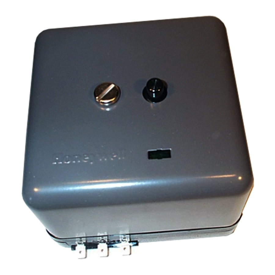
The RA890F Protectorelay™ Primary Control
is a nonprogramming, amplifying relay that pro-
vides solid state electronic flame safeguard pro-
tection for industrial and commercial gas, oil, or
combination gas-oil burners.
Employs rectification principle of electronic flame
detection using a flame rod, rectifying photocell, or
C7012A,C Ultraviolet Flame Detector.
Clipping pilot link jumper wire permits use with
standing pilots.
Can directly replace RA890E and mount on same
Q270A Subbase.
Solid state circuitry eliminates vacuum tube replace-
ment and increases resistance to vibration. Power
application not required during Off cycle; no tube to
warm up before starting.
Push-to-reset safety switch in dust-resistant enclosure.
Built-in protection against ignition crossover in flame
rod systems.
Does not start if flame-simulating failure occurs in
flame detector circuit.
Automatic safety shutdown if flame fails on start, or
if flame not re-established after flame failure.
S.Y. • Rev. 11-94 • ©Honeywell Inc. 1994
Flame Safeguard
Primary Control
Flame signal current is directly measurable at test
jack.
Line or 24 volt, automatic or manual controller can be
used. (Manual controller must open circuit on either
power or flame failure.)
Captive mounting screws allow easy mounting and
removal. Thermoplastic mounting base.
Optional alarm circuit indicates safety shutdown.
CONTENTS
Specifications ................................................. 2
Ordering Information ..................................... 2
Installation ..................................................... 4
Operation ....................................................... 7
Checkout ......................................................... 8
Service .......................................................... 10
Troubleshooting and Maintenance .............. 10
1
RA890F
60-2034-7
60-2034-7
Advertisement

Related Manuals for Honeywell RA890F


Summary of Contents for Honeywell RA890F
-
Page 1: Table Of Contents
Specifications ..........2 Ordering Information ........2 Installation ............. 4 Operation ............7 Checkout ............8 Service ............10 Troubleshooting and Maintenance ....10 S.Y. • Rev. 11-94 • ©Honeywell Inc. 1994 60-2034—7 60-2034-7... -
Page 2: Specifications
If you have additional questions, need further information, or would like to comment on our products or services, please write or phone: 1. Your local Honeywell Home and Building Control sales office (check white pages of phone directory). 2. Home and Building Control Customer Logistics Honeywell Inc., 1985 Douglas Drive North... - Page 3 For RA890s that are blocks with coded terminals and screws. classified in Underwriters Laboratories Inc gas groups 6 R482F Relay to provide safe-start checks when RA890F and 6A and oil group 8, the maximum safety switch is used in special standing pilot applications.
-
Page 4: Installation
(line voltage) wiring. When wiring the Q270A Universal Mounting Base for LOCATION use with the RA890F, use the terminal designations 6, T and Temperature T (printed in white). Install the RA890F where the surrounding temperatures 2A. For normal installations, use moisture-resistant remain within the Ambient Operating Temperature Ratings No. - Page 5 DETECTOR RA890E Replacement (FLAME ROD OR When replacing an RA890E with an RA890F, no changes UV DETECTOR) are required in the wiring to the subbase. Leave the hot line connected to terminal 1 even though it is not required to operate the control.
- Page 6 WIRE JUMPER (PILOT LINK) PROVIDE DISCONNECT MEANS AND OVERLOAD PROTECTION AS REQUIRED. RA890F IS POWERED AT TERMINAL 6 ONLY. WHEN REPLACING ANOTHER MODEL, LEAVE HOT LINE (L1) CONNECTED TO TERMINAL 1, EVEN THROUGH IT IS NOT NECESSARY FOR OPERATION. (HOT) MAY USE LINE OR LOW VOLTAGE CONTROLLER.
-
Page 7: Operation
Disconnect power supply. For use with standing pilot systems. Clip the pilot link Remove relay cover (see Fig. 6) and position the RA890F (wire loop in Fig. 7) as follows: over the Q270A Subbase. Start all ten mounting screws and 1. -
Page 8: Checkout
1. The flame current is steady; meter does not vary more RA890 than a needle width. M8755 2. The flame current is at least two microamperes for a rectification type detector like used with the RA890F. The normal operating range is 2 to 5 microamperes. 60-2034—7... - Page 9 Use manual reset limits with the RA890F to prevent the in the flame relay. Perform a flame current check before and system from cycling off the high limit and to assure that the after the pilot turndown test.
-
Page 10: Service
(See controller instructions.) 5. Clean contacts only when required by failure to oper- 5. Never use oil on any part of the RA890F. ate properly. 6. When cleaning the burner, clean the flame detector. - Page 11 If the current is not satisfactory, check all items listed is not sufficient to destroy the RA890E, but is sufficient in the Flame Current Check section. to prevent operation of the RA890F due to its arc gap protection. Be very suspicious of ignition interference OBSERVE SEQUENCING OPERATION on any installation where the RA890E operates and 13.
- Page 12 Home and Building Control Home and Building Control Helping You Control Your World Honeywell Inc. Honeywell Limited—Honeywell Limitée 1985 Douglas Drive North 740 Ellesmere Road Golden Valley, MN 55422 Scarborough, Ontario M1P 2V9 QUALITY IS KEY 60-2034—7 Printed in U.S.A.