Advertisement
Available languages
Available languages
Quick Links
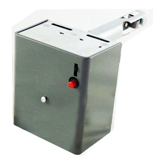
The RA116A Protectorelay Oil Burner Control is a
stack-mounted oil primary control that provides line volt-
age switching of intermittent ignition burners (formerly
called constant ignition burners). The RA116A is used
with a Honeywell series 10, 3-wire thermostat; any 24V, 2-
wire thermostat; or any line volt thermostat or controller.
The thermostat heat anticipator setting must be adjusted to
0.4A for 24V thermostats only.
If the burner fails to ignite during startup, a safety switch
Honeywell
R116A,B
R124A,B
R134A
R168A
R494A
RA116A,B
RA416A
a
RA816A,D
Penn
664
670
680
a
When replacing a model with an F or O terminal to power a clogged filter indicator light, provide a separate transformer
for the light.
b
A Detroit 3-wire thermostat must be replaced by a 2-wire thermostat with a suitable heat anticipator.
WHEN INSTALLING THIS PRODUCT...
1. Read these instructions carefully. Failure to follow
them could damage the product or cause a hazardous
condition.
2. Check the ratings given in these instructions and on
the product to make sure the product is suitable for your
application.
3. Installer must be a trained, experienced service tech-
nician.
4. After installation is complete, check out product
operation as provided in these instructions.
RA116A Protectorelay
Application
TABLE 1—RA116A CROSS-REFERENCE.
White Rodgers
603
611-1
611-31
611-33
615
6L18
ITT General
5200
R96A102A
R96G102DC
Installation
C.H. • 2-92 • © Honeywell Inc. 1992 • Printed in U.S.A • Form Number 69-0650B
Oil Burner Control
trips and locks out the burner system. To restart, the safety
switch must be reset manually. If the burner flame goes out
during burner operation, the Protectorelay Control locks
out unless the flame is reestablished within the 75 second
(nominal) safety switch timing. If the power supply fails,
the control returns to the starting position, ready to restart
when power is restored.
The RA116A is designed to replace existing controls
listed in Table 1. Ensure the electrical ratings and element
insertion length are suitable before installing.
General Electric
A101B2
CR7865
Mercoid
JM
CAUTION
!
1. Do not bend contact arms or stops on the
Pyrostat detector mechanism or make any ad-
justments other than those given in the instruc-
tions.
2. Remove the cardboard packing behind the
drive shaft lever by pushing the packing up and
pulling it straight out over the top of the lever.
Do not remove packing by pulling sideways.
3. Ensure all wiring complies with applicable
codes and ordinances.
General Perfex
5200
5300
Detroit
b
CA701
b
CA702
Advertisement

Related Manuals for Honeywell RA116A


Summary of Contents for Honeywell RA116A
- Page 1 3. Ensure all wiring complies with applicable 4. After installation is complete, check out product codes and ordinances. operation as provided in these instructions. C.H. • 2-92 • © Honeywell Inc. 1992 • Printed in U.S.A • Form Number 69-0650B...
-
Page 2: Startup And Checkout
3, 4, M, or MOTOR If the position of the old control was satisfactory, install WARNING the new RA116A in the same location as the old one. Be sure to insert the bimetal element the same distance into the FIRE HAZARD stack as the old element. - Page 3 Simulate flame failure: 1. Follow the starting procedure to turn on the burner. BURNER MOTOR 2. Close the hand valve in the oil supply line. 3. Notice the RA116A locks out after 75 second (nomi- HIGH IGNITION nal) safety switch timing. LIMIT 4.
- Page 4 Home and Building Control Home and Building Control Helping You Control Your World Honeywell Inc. Honeywell Limited—Honeywell Limitée 1985 Douglas Drive North 740 Ellesmere Road Golden Valley, Minnesota 55422 Scarborough, Ontario M1P 2V9...
-
Page 5: Installation
3. S’assurer que tous les raccordements présentes instructions. respectent les codes et règlements locaux en vigueur. C.H. • 2-92 • © Honeywell Inc. 1992 • Printed in U.S.A. • Form Number 69-0650B... - Page 6 Si l’ancienne Vérification bilame était insérée à plus de 140 mm [5 1/2 po], insérer le nouveau RA116A à 140 mm [5 1/2 po] dans le MISE EN GARDE conduit de fumée. Si la position de l’ancien régulateur ne convient plus, boucher l’ancienne ouverture au moyen d’une...
-
Page 7: Mise En Marche Du Système
2. Refermer le robinet manuel de la canalisation TERRE DU BOÎTER MF1585A d’alimentation en mazout. 3. Le RA116A se met sous sécurité après un délai de 75 secondes (nominal). Fig. 3—Schéma de raccordement d’un RA116A 4. Réarmer l’interrupteur de sécurité et ouvrir le avec un régulateur ou un thermostat tension... - Page 8 à mazout ou du dispositif d’allumage afin d’éviter tout choc électrique. Département de la Régulation Résidentielle et Commerciale Pour la maîtrise de votre univers. Honeywell Limited-Limitée Honeywell Inc. 740 Ellesmere Road 1985 Douglas Drive North Scarborough (Ontario) M1P2V9...