
Related Manuals for Yamaha G20A


Summary of Contents for Yamaha G20A
- Page 1 MULTI- PASSENGER VEHICLE OWNER’S/ OPERATOR’S MANUAL G20A JR8-F8199-00 LIT-19626-20-00...
- Page 2 WARNING The engine exhaust from this product contains chemicals known State of California to cause cancer, birth defects or other reproductive harm. YAMAHA LIT-CALIF-65-01...
- Page 3 Yamaha. If you have any questions about the operation or maintenance of your vehicle, please consult a Yamaha dealer. TECHNICAL SERVICE DEPT GOLF CAR SALES GROUP YAMAHA MOTOR MANUFACTURING CORP.
- Page 4 IMPORTANT MANUAL INFORMATION Particularly important information is NOTE distinguished in this manual by the fol- Yamaha continually seeks ad- lowing notations: vancements in product design and quality; therefore, while this manual contains the most current product information available at the time of...
-
Page 5: Table Of Contents
CONTENTS WARRANTY IMPORTANT LABELS OCCUPANT SAFETY MAINTENANCE SAFETY PROGRAM CONTROLS PRE-OPERATION CHECKS OPERATION MAINTENANCE STORAGE SPECIFICATIONS WIRING MULTI-PASSENGER... -
Page 6: Warranty
Give notice to an authorized Yamaha dealer of any and all apparent defects within ten (10) THE PERIOD OF WARRANTY for any G20A will be days after discovery, and make the machine one year from date of purchase for parts and labor. - Page 7 In complance with the California Air Resources You are responsible for presenting your specialty Board, Yamaha Motor Manufacturing Corporation of vehicle engine to a Yamaha dealer as soon as a America is pleased to explain the emission control problem exists. The warranty repairs should be...
- Page 8 Catalyst or Thermal Reactor System ment, or repair of emission control systems be Catalytic converter Yamaha parts. The owner may elect to have main- Thermal reactor tenance, replacement, or repair of the emission Exhaust manifold...
-
Page 9: Important Labels
IMPORTANT LABELS SAFETY AND INSTRUCTION LABELS WARNING Please read the following labels carefully before oper- ating your multi-passenger vehicle, promptly replace any labels which become damaged removed. Y-191A Y-191B Y-500 Vehicle capacity : 2 occupants per seat, 4 persons total. V e h i c l e c a p a c i t y : 2 o c c u p a n t s p e r s e a t , 4 p e r s o n s t o t a l MULTI-PASSENGER... - Page 10 NOTE The first three digits of the serial num- Y-102a ber are for model identification; the remaining digits are the unit produc- tion number. Keep a record of these numbers for reference when ordering parts from a Yamaha dealer. MULTI-PASSENGER...
-
Page 11: Occupant Safety
OCCUPANT SAFETY Yamaha vehicles are designed to be simple to operate. However, be sure to observe the following: BEFORE OPERATING THE MULTI-PASSENGER VEHICLE Read this Owner’s/Operator’s manu- al and all safety and instruction labels on the vehicle before operating. Perform the pre-operation checks found in Section 6 of this manual. - Page 12 OCCUPANT SAFETY WHILE OPERATING THE MULTI-PASSENGER VEHICLE Always drive slowly straight up or straight down slopes – never at an angle. Vary the speed of the vehicle to match the terrain of the path. Avoid turning the steering wheel too sharply at higher speeds.
-
Page 13: Maintenance Safety Program
Parts and Materials. Use only the vehicle must be driven by a qual- replacement parts and materials ified, trained, and authorized person recommended by Yamaha. – in an area free of pedestrian traffic – to ensure proper operation and Ventilation. Properly ventilate all adjustment. -
Page 14: Battery Charging
MAINTENANCE SAFETY PROGRAM FUEL HANDLING/ STORAGE AND BATTERY CHARGING Take the following precautions to ensure maintenance worker safety: Supervise the storage and handling of liquid fuels in accordance with applicable fire and safety require- ments. Only use battery changing and charging facilities and procedures that are in accordance with applica- ble ordinances and regulations. -
Page 15: Controls
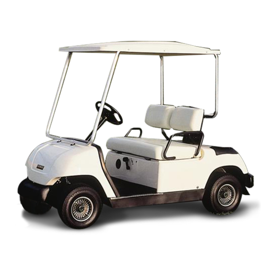
CONTROLS FEATURES 1 Steering wheel 2 Front seat 3 Rear seat 4 Battery 5 Brake pedal 6 Parking brake pedal Y-12 7 Accelerator pedal 8 Drive selector lever 9 Main switch a Oil warning light b Choke knob c Front cowl d Front tire e Front bumper f Rear cowl... -
Page 16: Main Switch
CONTROLS MAIN SWITCH The main switch controls the following items: Ignition circuit is switched off. The key can be removed only in this position. Y-15 Electrical circuits are switched on. The vehicle can be driven. Y-16 OIL WARNING LIGHT When the engine oil level falls below an acceptable level, this light comes on. -
Page 17: Drive Select Lever
CONTROLS DRIVE SELECT LEVER The drive select lever is used to shift the vehicle into forward or reverse. After coming to a complete stop, move the lever to the desired position. Y-18 Lever Position Car Movement FORWARD REVERSE NOTE The back-up buzzer will beep when the drive select lever is turned to “R.”... -
Page 18: Parking Brake Pedal
CONTROLS PARKING BRAKE PEDAL Press down on the parking brake pedal whenever parking the vehicle. å Parking brake pedal NOTE Release the parking brake by de- Y-22 pressing the accelerator pedal. CHOKE KNOB Pull and hold out choke knob when starting a cold engine. -
Page 19: Pre-Operation Checks
PRE-OPERATION CHECKS Pre-operation checks should be made each time you use your vehicle. Get in the habit of performing the following checks in the same way so that they become second nature. WARNING Be sure the main switch key is removed before performing the pre-operation checks to prevent accidental starting, and apply the... -
Page 20: Fuel System
PRE-OPERATION CHECKS FUEL SYSTEM Make sure there is sufficient fuel in the tank, and check fuel line and connec- tions for leakage. å Fuel tank ∫ Fuel cap Y-191I WARNING Gasoline and its vapors are highly flammable and explosive. Do not smoke when refueling and keep away from sparks, flames, or other sources of ignition. -
Page 21: Engine Oil
PRE-OPERATION CHECKS ENGINE OIL With the vehicle parked on level ground, remove the dipstick and make sure the engine oil is between the MIN and MAX marks (the crosshatched area on the end of the dipstick). Y-514 å Oil level dipstick ∫... -
Page 22: Tire Wear Limit
PRE-OPERATION CHECK Engine Cooling Inlet Duct Check the engine cooling inlet duct for debris. Remove any debris present. å Engine cooling inlet duct BATTERY Check that the battery is held secure- ly in place to prevent the battery from Y-191L being damaged from vibration or jar- ring. -
Page 23: Brake Pedal
Y-33 PEDAL OPERATION Check the following pedal controls for proper operation. If a pedal does not work properly, consult a Yamaha deal- Brake Pedal Make sure the brake pedal feels firm when pressed and returns to its origi- nal position when released. -
Page 24: Accelerator Pedal
PRE-OPERATION CHECKS Parking Brake Pedal WARNING Before checking operation of the parking brake, be sure the main switch is in the “OFF” position. Make sure the parking brake pedal Y-22 locks in place with a positive click, and releases when the accelerator pedal is pressed. -
Page 25: Operation
OPERATION STARTING 1. With the parking brake applied, turn the drive select lever to “F” for forward, or “R” for reverse. CAUTION Do not shift from “F” forward to “R” reverse while the vehicle is moving. Y-18 2. Turn the main switch to “ON.” WARNING Do not depress the accelerator pedal when turning on the main... - Page 26 OPERATION STOPPING To stop the vehicle, gradually press down on the brake pedal. å Brake pedal When the car has come to a stop, apply the parking brake pedal and turn the main switch to “OFF.” Y-65 ∫ Parking brake pedal CAUTION Do not hold the vehicle on an incline with the accelerator –...
-
Page 27: Maintenance
Check starter V-belt for damage and tension * Items with out a page number reference should be serviced by a Yamaha dealer or other qualified mechanic. This manual does not contain these procedures. They are contained in the Service Manual. - Page 28 Check for grease leakage; adjust gearbox if necessary * Items without a page number reference should be serviced by a Yamaha dealer or other qualified mechanic. This manual does not contain these procedures. They are contained in the Service Manual.
-
Page 29: Exhaust Emission Control System And Components
VEHICLES AND ENGINES. The acronyms conform to the latest version of the SAE’s recommended practice document J1930, “Diagnostic Acronyms, Terms, and Definitions For Electrical/Electronic System”. It is recommended that these items be serviced by a Yamaha dealer or other qualified mechanic. MULTI-PASSENGER... -
Page 30: Spark Plug Inspection
MAINTENANCE Spark Plug Inspection You should periodically remove and inspect the spark plug. Dirty or worn spark plugs can cause poor perfor- mance. å Spark plug ∫ Spark plug cap 1. Check for discoloration and heavy Y-516 carbon deposits. The normal electrode color will be tan. - Page 31 MAINTENANCE Engine Oil Replacement 1. Warm up the engine for several minutes, place the vehicle on a level surface, then stop the engine. WARNING Use caution not to touch hot engine oil or hot engine parts during the following procedure. 2.
-
Page 32: Air Filter
After replacing engine oil, check for oil leaks around the drain plug. If oil leaks are found, consult Y-515 a Yamaha dealer. Air Filter To remove the air filter elements: 1. Unlatch the air filter cover clips and remove cover. - Page 33 MAINTENANCE Inspection and cleaning: 3. Wash the foam pre-filter in soap and water. Allow it to dry. å Soap and water ∫ Foam element 4. Check the filter element. If dam- Y-508 aged or dirty, replace it. CAUTION Do not wring out the foam pre-fil- ter, this could cause it to tear.
-
Page 34: Drive Belt
MAINTENANCE Drive Belt To remove the drive belt: 1. Set the drive select lever halfway between forward and reverse. 2. Pull up on the drive belt and push it outward over the edge of the secondary sheave. 3. Turn the secondary sheave clock- wise and the drive belt will roll off the sheave. - Page 35 MAINTENANCE Battery WARNING Battery electrolyte is poisonous and dangerous, causing severe burns, etc. It contains sulfuric acid. Avoid contact with skin, eyes, or clothing. Antidote: EXTERNAL: Flush with water. INTERNAL: Drink large quantities of water or milk. Follow with milk of magnesia, beaten egg, or vegetable oil.
-
Page 36: Fuse Replacement
MAINTENANCE Fuse Replacement WARNING Be sure to use the specified fuse. Using a wrong fuse can cause elec- trical system damage and create a fire hazard. CAUTION Y-35 When replacing a fuse be sure the main switch is turned off to prevent Replacement Fuse: accidental short-circuiting. -
Page 37: Brake Adjustment
Do not allow foreign material to enter the gear box. 5. Reinstall the oil plug. NOTE For gear oil replacement, consult a Yamaha dealer or other qualified mechanic. Wheel Replacement To remove and install a wheel on your vehicle: 1. With the wheels blocked to prevent the vehicle from moving, loosen the wheel nuts. -
Page 38: Brake Pedal Free Play Adjustment
MAINTENANCE Brake Pedal Free Play Adjustment CAUTION Before adjusting brake pedal free play, pump the brake pedal several times to self-adjust the brakes. To adjust the brake pedal free play: 1. Remove the service lid from the floor of the vehicle. Y-61 2. -
Page 39: Storage
STORAGE Perform the following preparations when storing your vehicle for extend- ed periods of time: NOTE Turn main switch key to “OFF” position, remove key, and store key in a safe place. DRAINING FUEL WARNING Gasoline and its vapors are highly flammable and explosive. -
Page 40: Engine Preparation
STORAGE ENGINE PREPARATION BATTERY PREPARATION With the key removed and the spark plug lead disconnected, turn the 1. Remove the battery from the vehi- clutch by hand until compression is cle and store it in a cool, dry place felt. This puts the valves in the closed that stays between 32°F (0°C) and position. -
Page 41: Specifications
SPECIFICATIONS GENERAL SPECIFICATIONS Items G20A Dimensions: Overall length 128.0 in. (3250 mm) Overall width 47.2 in. (1200 mm) Overall height (steering height) 46.8 in. (1190 mm) Height of floor 11.8 in. (300 mm) Wheelbase 97.8 in. (2483 mm) Tread: Front 34.3 in. - Page 42 SPECIFICATIONS ENGINE Items G20A Description: Engine type 4-stroke, Gasoline, OHV Number of cylinders Single Displacement 301 cm Bore x stroke 3.07 x 2.48 in. (78 x 63 mm) Compression ratio 8.1:1 Rated output 9.5 hp (7.1 kw)/4000 rpm Cooling system...
- Page 43 (Bolt heads round parallel to arm) 0.04 in. (1 mm) Wheel: Tire size: Front 18 x 8.50–8.00/4 PR Rear 18 x 8.50–8.00/TURF Rim size: 7.00–I–8.00 Tire pressure: For G20A: 20 - 23 psi (140 - 160 kPa, 1.4 - 1.6 kgf/cm 2 ) 10-3 MULTI-PASSENGER...
-
Page 44: Wiring
WIRING G20A WIRING DIAGRAM 11-1 MULTI-PASSENGER... - Page 45 WIRING 1 Engine stop relay 2 Engine ground 3 Pickup 4 Rotor 5 Oil level gauge 6 Blade fuse (10A) 7 Voltage regulator 8 Starter generator 9 Relay a Battery b Pilot lamp (12V, 3.4W) c Main switch d Accelerator stop switch e Back switch f Buzzer g Body ground...
- Page 46 10/31/00 1PC - G20A O/M LIT196262000 *LIT196262000* Yamaha Motor Corp., USA made in Cypress, California YAMAHA MOTOR MANUFACTURING CORP. OF AMERICA Printed in U.S.A.