Table of Contents
Advertisement
Quick Links
Advertisement
Table of Contents

Related Manuals for Grizzly G0484


Summary of Contents for Grizzly G0484
- Page 1 GEARHEAD MILL/DRILL WITH STAND OWNER'S MANUAL COPYRIGHT © APRIL, 2007 BY GRIZZLY INDUSTRIAL, INC., REVISED JANUARY, 2008 (TS) WARNING: NO PORTION OF THIS MANUAL MAY BE REPRODUCED IN ANY SHAPE OR FORM WITHOUT THE WRITTEN APPROVAL OF GRIZZLY INDUSTRIAL, INC.
- Page 2 ���� ������ �������� �������� ������ ������������ �� ��� ������ ������ ���������� ����������� ��� ������� �� ���� ������������������ ������� �� ����� ���������� ��� ������ ��� ������������ ����� �� ���� ������ ��� ������ �� ������� �������� ������� ��������� ����������� ������������� �� ������ ���...
-
Page 3: Table Of Contents
Lubrication ... 24 SECTION 7: SERVICE ... 26 Troubleshooting ... 26 Adjusting Gibs ... 27 G0484 Wiring Diagram ... 28 220V Single Phase ... 28 Electrical Component Index ... 29 Table Parts Breakdown ... 32 Column Parts Breakdown ... 34 Head Parts Breakdown, Part A ... -
Page 4: Introduction
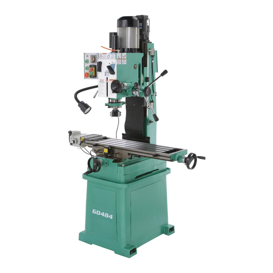
INTRODUCTION Foreword We are proud to offer the Model G0484 Gearhead Mill/Drill with Stand. This machine is part of a grow- ing Grizzly family of fine metalworking machinery. When used according to the guidelines set forth in this manual, you can expect years of trouble-free, enjoyable operation and proof of Grizzly’s com-... -
Page 5: Machine Data Sheet
���������������������������������������������������������������������������������������������������������������������������������������������������������������������� ������������������������������������������������������������������������������������������������������������������������������������������������������������������������� ����������������������������������� � ����������������������������������������������������������������������������������������������������������������������� ������������������������������������������������������������������������������������������������������������������������������������������������������������� �������������� � ��������������������������������������������������������������������������������������������������������������������������������������������������������������� ��� ��������������������������������������������������������������������������������������������������������������������������������������������������������������������������� �������������������������������������������������������������������������������������������������������������������������������������������������������������������������� �������������������������������������������������������������������������������������������������������������������������������������������������������������������������� ������������������������������������������������������������������������������������������������������������������������������������������������������������������������������� �� ������������������ � ������������������������������������������������������������������������������������������������������������������������������������������������������������ � ���������������������������������������������������������������������������������������������������������������������������������������������������������������������������������� ������������������������������������������������������������������������������������������������������������������������������������������������������������������������������� ������������������������������������������������������������������������������������������������������������������������������������������������������������������������������ G0484 Gear Head Mill/Drill ������� ���� ����� � � � � � � � � � � �... - Page 6 ������������������������������������������������������������������������������������������������������������������������������������������������������������������������������������� �� ����������������������������������������������������������������������������������������������������������������������������������������������������������������������������������� �������������������������������������������������������������������������������������������������������������������������������������������������������������������������������� ���� ����������������������������������������������������������������������������������������������������������������������������������������������������������������������������� � ��������������������������������������������������������������������������������������������������������������������������������������������������������������������������������� ��������� �������������������� ������������������������ ������������ ������������������ ������������������������������������������ ���������������� ������������������� �������� ����������������������������������� ���������������������������������� ����������������� ��������������������������������� � ��� � � � � � � � � ��� � � � � � G0484 Gear Head Mill/Drill...
-
Page 7: Identification
X-Axis Handwheel Power Feed Rapid Feed Switch K. Power Feed Power Switch Power Feed Speed Dial M. Power Feed Direction Lever G0484 Gear Head Mill/Drill Identification Figure 1. G0484 Identification. N. Work Lamp O. Quill Lock Lever P. Quill Depth Limiter Q. -
Page 8: Section 1: Safety
�������� ���������������������������������������������� ��� �������� ����� ���� ������ ��� ������� ������� ����� ����������� ����� ��������� ��� �������� ������������������������������������� �� ����� ������� ��������� ���� ����� �� ����� ��� ��������� �� ��������� ����� �� �������� ������������������ ������������������������������������ ��������� ����������� G0484 Gear Head Mill/Drill... - Page 9 ��� �������� ��������� ���� ������ ����������������������������������������� �������������������������������������������� ������������������������������������� ��� ���� ���� ������ ��� �� ����� ��� ���� ��������� ������ ����� ���������� G0484 Gear Head Mill/Drill ��� ������ ��������������������������������������� ����� ���� ���������� ��������� ������� ����� ����������������� ��� ����� ������ ����� ���������������������...
-
Page 10: Additional Safety Instructions For Mill/Drills
Use this and other machinery with caution and respect. Failure to do so could result in serious per- sonal injury, damage to equipment, or poor work results. G0484 Gear Head Mill/Drill... -
Page 11: Section 2: Circuit Requirements
DO NOT connect the machine to the power source until instructed to do so. Amperage Draw The Model G0484 motors draws the following amps under maximum load: Motor Draw at 220V ... 8 Circuit Requirements... -
Page 12: Section 3: Setup
Cleaning Solvent ... As Needed • Shop Rags ... As Needed Unpacking The Model G0484 was carefully packed when it left our warehouse. If you discover the machine is damaged after you have signed for delivery, please immediately call Customer Service at (570) 546-9663 for advice. -
Page 13: Inventory
G. Handwheels ... 2 H. Chuck 1–16mm JT3 ... 1 Chuck Key ... 1 Handwheel Handles ... 2 Figure 3. Model G0484 inventory. NOTICE Some hardware/fasteners on the inventory list may arrive pre-installed. Check mount- ing locations before assuming that any items from the inventory list are missing. -
Page 14: Site Considerations
���� ��� To lift the G0484 from the base, remove both side panels of the base (see Figure 6). Carefully place the lift forks completely through the base cavity. Be sure to use assistance in this process and only lift the mill/drill enough to clear floor obstacles as you move it to its permanent position. -
Page 15: Mounting To Shop Floor
Figure 7. Typical fasteners for mounting to concrete floors. G0484 Gear Head Mill/Drill Assembly To assemble your mill/drill: Place the handwheels on the longitudinal and cross lead screws, and tighten the set screw (see Figure 8). -
Page 16: Test Run
—If the machine does start (with the stop button pushed in), immediately disconnect power to the machine. The OFF button safety feature is not working correctly. This safety feature must work properly before proceeding with regular operations. Call Tech Support for help. G0484 Gear Head Mill/Drill... -
Page 17: Break-In
Use the gearbox levers so that the spindle RPM is set at 120. G0484 Gear Head Mill/Drill Twist the emergency stop button clockwise so that it pops out. Switch the spindle rotation dial to "F" (for- ward) and let the spindle run for 10 minutes. -
Page 18: Section 4: Operations
OMMEND that you read books, trade maga- zines, or get formal training before begin- ning any projects. Regardless of the con- tent in this section, Grizzly Industrial will not be held liable for accidents caused by lack of training. -16- Control Panel A. -
Page 19: Spindle Height Control
Quill Feed Lever Fine Feed Knob Quill Lock Lever Fine Feed Lock Knob Figure 12. Spindle controls. G0484 Gear Head Mill/Drill Table Travel (X-Axis and Y-Axis) Longitudinal Feed The longitudinal feed, or X-axis, is moved by the handwheel at the right end of the table. The handwheel will move the table in both direc- tions side-to-side. -
Page 20: Tooling Changes
Lightly strike the drawbar with a dead blow hammer (Figure 14) or a piece of wood to release the tooling from the spindle. Hold the tooling, and unscrew the drawbar. Drawbar NOTICE G0484 Gear Head Mill/Drill... -
Page 21: Choosing Spindle Rpm
Note: Double the cutting speed for carbide cutting tools. These values are a guideline only. Refer to the MACHINERY'S HANDBOOK for more detailed information. G0484 Gear Head Mill/Drill Measure the diameter of your cutting tool in inches. Use the following formula to determine the... -
Page 22: Milling/Drilling
Guidelines may threaten operator safety from ejected parts or broken tools. Spindle Scale Quill Feed Lever Fine Feed Knob Quill Lock Lever Fine Feed Lock Knob Figure 16. Milling/drilling controls. Figure 17. Headstock tilt lock. Figure 18. Headstock lock levers. G0484 Gear Head Mill/Drill... -
Page 23: Section 5: Accessories
6 step block pairs, 6 T-nuts, 6 flange nuts, 4 coupling nuts, and 6 end hold-downs. Figure 20. G1075 52-PC. Clamping Kit. G0484 Gear Head Mill/Drill G9324—Boring Head Combo Set Hardened and ground adjusting screws along with a wide base design guarantee a long life and trouble-free use. - Page 24 You can't be too careful when it comes to shop safety! H1300 H2347 Figure 27. Our most popular safety glasses. Spitfire Safety Glasses ® Safety Glasses ® H1298 G7984 H0736 G0484 Gear Head Mill/Drill...
-
Page 25: Section 6: Maintenance
Any other condition that would hamper the safe operation of this machine. Weekly Maintenance: • Gibs are adjusted properly and lubricated. G0484 Gear Head Mill/Drill Cleaning and Protecting Metal chips left on the machine that have been soaked with water-based coolant will invite oxida- tion and a gummy residue build-up around the moving parts. -
Page 26: Lubrication
After cleaning the longitudinal and cross lead screws of all debris, paint a small amount of white lithium grease on each one. Then, move the attached part all the way through its full range of motion on the lead screw. G0484 Gear Head Mill/Drill... - Page 27 Rubber Chip Curtain Lead screw Figure 30. Headstock lead screw access and lubrication. G0484 Gear Head Mill/Drill Headstock Gearbox Oil On an annual basis, or every six months under heavy use, we recommend that you drain and refill the headstock oil with a 10-30W non-deter- gent oil.
-
Page 28: Section 7: Service
4. Lubricate ways and tighten gibs. 5. Vise or clamping fixture is worn, loose, or inadequate for clamping task. 6. Incorrect spindle speed or feed rate. 1. Rotate spindle by hand until gear falls into place. G0484 Gear Head Mill/Drill... -
Page 29: Adjusting Gibs
Each sliding dovetail on the Model G0484 has a gib that is sandwiched between two adjusting screws (see Figures 32–33 for the locations of the gib adjustment screws). -
Page 30: G0484 Wiring Diagram
��������� ��������� ������ ����� ������ ����� ����� ������ ����� ������ � �� ��� ��� � �� ��� ��� � �� �� � � � � ���� ���� � � � � � � � � G0484 Gear Head Mill/Drill ��... -
Page 31: Electrical Component Index
Figure 1. Mill/drill front left view. Page 30, Page 30, Figure 38. Figure 37. Page 31, Figure 39. Page 31, Figure 35. Figure 2. Mill/drill right rear view. -29- G0484 Gear Head Mill/Drill... - Page 32 Figure 36. Master power switch. Figure 34. Spindle motor rotary switch, left and right view. Figure 37. Spindle motor capacitors and wiring connections. Figure 35. Lift motor capacitor and wiring box. Figure 38. Lift motor junction box. -30- G0484 Gear Head Mill/Drill...
- Page 33 Figure 39. Main wiring box. -31- G0484 Gear Head Mill/Drill...
-
Page 34: Table Parts Breakdown
�� �� �� �� �� �� �� �� �� � �� �� �� �� �� �� �� �� �� �� � � � � �� � � � � �� � � �� �� �� �� G0484 Gear Head Mill/Drill... - Page 35 P0484017 BASE P0484018 STAND PS17M PHLP HD SCR M4-.7 X 6 P0484020 FRONT PANEL P0484021 SIDE PANEL PW06M FLAT WASHER 12MM G0484 Gear Head Mill/Drill Table Parts List PART # PB157M P0484024 P0484025 P0484026 P0484027 P0484028 P0484029 PSB31M P0484031 P0484032...
-
Page 36: Column Parts Breakdown
��� ����� ����� ��� ��� ��� ��� ��� ��� ����� ��� ��� ��� ��� ��� ��� ��� ��� ��� ��� ��� ��� ��� ��� ��� ��� ��� ��� ��� ��� ��� ��� ��� ��� ��� -34- G0484 Gear Head Mill/Drill... -
Page 37: Column Parts List
THRUST BEARING 15 X 28 X 9MM P0484119 TOP CLUTCH PSS03M SET SCREW M6-1 X 8 P0484121 BOTTOM CLUTCH P0484122 COMPRESSION SPRING G0484 Gear Head Mill/Drill PART # DESCRIPTION P0484123 SPRING BASE P0484124 LEAD SCREW NUT P0484125 HEADSTOCK MOUNT P0484126... -
Page 38: Head Parts Breakdown, Part A
��� ����� ��� ��� ��� ��� ��� ��� ��� ��� ��� ��� ��� ��� ��� ��� ��� ��� ��� ��� ��� ��� ��� ��� ��� ��� ��� ��� ��� ��� G0484 Gear Head Mill/Drill ��� ��� ��� ��� ��� ���... -
Page 39: Head Parts Breakdown, Part B
HEAD B Head Parts Breakdown, Part B -37- G0484 Gear Head Mill/Drill... -
Page 40: Head Parts List
LEVER ( LEFT ) LEVER BRACKET LEVER ( RIGHT ) LEVER SHAFT ( RIGHT ) PHLP HD SCR M4-.7 X 6 SPECIAL NUT HEAD BODY BUSHING OIL COVER SIGHT GLASS SCALE PHLP HD SCR M5-.8 X 8 KNOB SUPPORT G0484 Gear Head Mill/Drill... - Page 41 TAPERED ROLLER BEARING P0484300 BEARING CUP P0484301 SPINDLE PFH19M FLAT HD SCR M4-.7 X 10 P0484303 PINION SHAFT P0484304 KEY 8 X 7 X 22 G0484 Gear Head Mill/Drill Head Parts List PART # P0484305 PSB31M P0484307 P0484308 P0484309 P0484310 P0484311 P0484312...
-
Page 42: Label Placement
MUST maintain the original location and readability of the labels on the machine. If any label is removed or becomes unreadable, REPLACE that label before using the machine again. Contact Grizzly at (800) 523-4777 or www.grizzly.com to order new labels. -40-... -
Page 43: Warranty And Returns
WARRANTY AND RETURNS Grizzly Industrial, Inc. warrants every product it sells for a period of 1 year to the original purchaser from the date of purchase. This warranty does not apply to defects due directly or indirectly to misuse, abuse, negligence, accidents, repairs or alterations or lack of maintenance. - Page 45 ���������������������������������������������������������������������������������� � ������������������������������������������������������������������������������������ ����� ����������������������� ������ � ������������������������ ���� ��������������������� ���������������������������� ������ ������������������������ ���������� � ���������������� ���������������������������� ������������������������������� ��������������������������� ��� ��������� ����������� �� ����� �� � ��������� ������ �� ���� �� ���� ��� ��������� �������� �� ���� �� ������� ������ �������� ��� ��������� �� ������� ��� ����������� �� �������� ������������� ���...
- Page 46 ���������������������� ���������������������� ����������������������������������� ����������������������������������� ������������������������������������� �������������������������������������� ������� ����������� ���� ���� ��� ���� ����������� �� ���������� �������������������������������������� ����� ����� ����...
- Page 48 ��� ������ ��� ���� ���� ������� ����� ��� ������� ����� ��� �������� ��� ������� � � � ���� ����� ��� � � �������� ������ ��� � ����� ������ � �� ��� �������� ������� � ������ �������� ������ ������� ������ �� ����� ������...