Honda WT40X Owner's Manual
Hide thumbs
Also See for WT40X:
- Owner's manual (194 pages) ,
- Owner's manual (68 pages) ,
- Owner's manual (44 pages)

Related Manuals for Honda WT40X


Summary of Contents for Honda WT40X
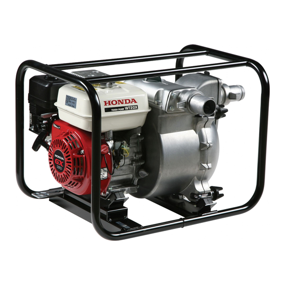
- Page 1 Owner s Manual WATER PUMP WT20X WT30X WT40X 2002-2009 Honda Motor Co., Ltd. -All Rights Reserved...
- Page 2 The information and specifications included in this publication were in effect at the time of approval for printing. Honda Motor Co., Ltd. reserves the right, however, to discontinue or change specifications or design at any time without notice and without incurring any obligation whatever.
- Page 3 INTRODUCTION Congratulations on your selection of a Honda water pump. We are certain you will be pleased with your purchase of one of the finest water pumps on the market. We want to help you get the best results from your new water pump and to operate it safely.
- Page 4 INTRODUCTION A FEW WORDS ABOUT SAFETY Your safety and the safety of others are very important. And using this water pump safely is an important responsibility. To help you make informed decisions about safety, we have provided operating procedures and other information on labels and in this manual.
-
Page 5: Table Of Contents
CONTENTS PUMP SAFETY ..................IMPORTANT SAFETY INFORMATION ..........SAFETY LABEL LOCATIONS ..............CONTROLS & FEATURES ................ COMPONENT & CONTROL LOCATIONS ..........CONTROLS ................... 10 Fuel Valve Lever ................10 Ignition Switch ................. . 10 Choke Lever ..................10 Throttle Lever .................. - Page 6 Carburetor Modification for High Altitude Operation ....51 Emission Control System Information .......... . 52 Specifications .................. . 54 CONSUMER INFORMATION .............. . 57 Honda Publications ................57 Customer Service Information ............58 QUICK REFERENCE INFORMATION ......Inside back cover...
-
Page 7: Pump Safety
PUMP SAFETY IMPORTANT SAFETY INFORMATION Honda WT20X, WT30X, and WT40X pumps are designed to pump only fresh water that is not intended for human consumption, and other uses can result in injury to the operator or damage to the pump and other property. - Page 8 PUMP SAFETY Hot Exhaust The muffler becomes very hot during operation and remains hot for a while after stopping the engine. Be careful not to touch the muffler while it is hot. Let the engine cool before transporting the pump or storing it indoors.
-
Page 9: Safety Label Locations
The labels shown here contain important safety information. Please read them carefully. These labels are considered permanent parts of your pump. If a label comes off or becomes hard to read, contact an authorized Honda servicing dealer for a replacement. WT20X PUMP CAUTION LABEL... - Page 10 PUMP SAFETY WT30X · WT40X PUMP CAUTION LABEL...
-
Page 11: Controls & Features
CONTROLS & FEATURES COMPONENT & CONTROL LOCATIONS WT20X FUEL FILLER CAP PRIMING WATER FILLER CAP AIR CLEANER THROTTLE LEVER CHOKE LEVER FUEL VALVE LEVER OIL FILLER CAP/DIPSTICK STARTER GRIP WRENCH CASE DRAIN PLUG PRIMING WATER FILLER CAP MUFFLER IGNITION SWITCH SUCTION PORT DISCHARGE PORT STRAINER... -
Page 12: Controls
CONTROLS & FEATURES CONTROLS Fuel Valve Lever The fuel valve opens and closes FUEL VALVE LEVER the connection between the fuel tank and the carburetor. The fuel valve lever must be in the ON position for the engine to run. When the engine is not in use, leave the fuel valve lever in the O F F p o s i t i o n t o p r e v e n t... -
Page 13: Throttle Lever
CONTROLS & FEATURES Throttle Lever THROTTLE LEVER The throttle lever controls engine speed. Moving the throttle lever in the directions shown makes the engine run faster or slower. Pump output is controlled by adjusting the throttle lever. At maximum throttle position, the pump will deliver the highest SLOW output volume. -
Page 14: Before Operation
BEFORE OPERATION ARE YOU READY TO GET STARTED? Your safety is your responsibility. A little time spent in preparation will significantly reduce your risk of injury. Knowledge Read and understand this manual. Know what the controls do and how to operate them. Familiarize yourself with the pump and its operation before you begin pumping. -
Page 15: Is Your Pump Ready To Go
BEFORE OPERATION IS YOUR PUMP READY TO GO? For your safety, and to maximize the service life of your equipment, it is very important to take a few moments before you operate the pump to check its condition. Be sure to take care of any problem you find, or have your servicing dealer correct it, before you operate the pump. -
Page 16: Check The Suction And Discharge Hoses
BEFORE OPERATION Check the Suction and Discharge Hoses Check the general condition of the hoses. Be sure the hoses are in serviceable condition before connecting them to the pump. Remember that the suction hose must be reinforced construction to prevent hose collapse. Check that the sealing washer in the suction hose connector is in good condition (see page Check that the hose connectors and clamps are securely installed... -
Page 17: Operation
OPERATION SAFE OPERATING PRECAUTIONS To safely realize the full potential of this pump, you need a complete understanding of its operation and a certain amount of practice with its controls. Before operating the pump for the first time, please review the IMPORTANT SAFETY INFORMATION on page and the chapter titled BEFORE OPERATION . -
Page 18: Pump Placement
OPERATION PUMP PLACEMENT For best pump performance, place the pump near the water level, and use hoses that are no longer than necessary. That will enable the pump to produce the greatest output with the least self-priming time. As head (pumping height) increases, pump output decreases. The length, type, and size of the suction and discharge hoses can also significantly affect pump output. -
Page 19: Suction Hose Installation
OPERATION SUCTION HOSE INSTALLATION Use the commercially available hose and hose connector with the hose clamp provided with the pump. The suction hose must be reinforced with a noncollapsible wall or braided wire construction. The suction hose should be no longer than necessary. Pump performance is best when the pump is near the water level, and the hoses are short. -
Page 20: Discharge Hose Installation
Priming water capacity: WT20X: 3.70 US gal (14.0 , 3.08 Imp gal) WT30X, WT40X: 3.96 US gal (15.0 , 3.30 Imp gal) Operating the pump dry will destroy the pump seal. If the pump has been operated dry, stop the engine immediately, and allow the pump to cool before priming. -
Page 21: Starting The Engine
OPERATION STARTING THE ENGINE Move the fuel valve lever to the ON position. To start a cold engine, move the choke lever to the CLOSED position. To restart a warm engine, leave the choke lever in the OPEN position. CHOKE LEVER Move the throttle lever away from the SLOW position, about 1/3 of the way toward the FAST position. - Page 22 OPERATION Turn the ignition switch to the ON position. IGNITION SWITCH Pull the starter grip lightly until you feel resistance, then pull briskly in the direction of the arrow as shown below. Return the starter grip gently. Direction to pull STARTER GRIP...
-
Page 23: Setting Engine Speed
OPERATION If the choke lever was moved to the CLOSED position to start the engine, gradually move it to the OPEN position as the engine warms CHOKE LEVER SETTING ENGINE SPEED After starting the engine, move the throttle lever to the FAST position for self-priming, and check pump output. -
Page 24: Stopping The Engine
OPERATION STOPPING THE ENGINE To stop the engine in an emergency, simply turn the ignition switch to the OFF position. Under normal conditions, use the following procedure. Move the throttle lever to the SLOW position. THROTTLE LEVER SLOW Turn the ignition switch to the OFF position. IGNITION SWITCH... - Page 25 OPERATION Turn the fuel valve lever to the OFF position. FUEL VALVE LEVER After use, remove the pump drain plug (see page ), and drain the pump chamber. Remove the filler cap, and flush the pump chamber with clean, fresh water. Allow the water to drain from the pump chamber, then reinstall the filler cap and drain plug.
-
Page 26: Servicing Your Pump
Other service tasks that are more difficult, or require special tools, are best handled by professionals and are normally performed by a Honda technician or other qualified mechanic. The maintenance schedule applies to normal operating conditions. If... -
Page 27: Maintenance Safety
SERVICING YOUR PUMP MAINTENANCE SAFETY Some of the most important safety precautions follow. However, we cannot warn you of every conceivable hazard that can arise in performing maintenance. Only you can decide whether or not you should perform a given task. Failure to properly follow maintenance instructions and precautions can cause you to be... -
Page 28: Maintenance Schedule
Service more frequently when used in dusty areas. These items should be serviced by your servicing dealer, unless you have the proper tools and are mechanically proficient. Refer to Honda shop manual for service procedures. For commercial use, log hours of operation to determine proper... -
Page 29: Refueling
SERVICING YOUR PUMP REFUELING Remove the fuel tank cap and check the fuel level. If the fuel level is low, refuel in a well-ventilated area with the engine stopped. If the engine has been running, allow it to cool first. Never refuel the engine inside a building where gasoline fumes can reach flames or sparks. -
Page 30: Fuel Recommendations
SERVICING YOUR PUMP Spilled fuel is not only a fire hazard, it causes environmental damage. Wipe up spills immediately. Fuel can damage paint and plastic. Be careful not to spill fuel when filling your fuel tank. Damage caused by spilled fuel is not covered under the Distributor’s Limited Warranty. -
Page 31: Engine Oil Level Check
SERVICING YOUR PUMP ENGINE OIL LEVEL CHECK Check the engine oil level with the engine stopped and in a level position. Remove the oil filler cap/dipstick and wipe it clean. Insert and remove the dipstick without screwing it into the filler neck. Check the oil level shown on the dipstick. -
Page 32: Engine Oil Change
(see page Engine oil capacity:WT20X....0.63 US qt (0.60 ) WT30X/WT40X.. 1.2 US qt (1.1 ) The Oil Alert system will automatically stop the engine before the oil level falls below the safe limit. However, to avoid the inconvenience of an unexpected shutdown, fill to the upper limit, and check the oil level regularly. -
Page 33: Engine Oil Recommendations
The SAE oil viscosity and service category are in the API label on the oil container. Honda recommends that you use API SERVICE category SJ or later (or equivalent) oil. -
Page 34: Air Filter Inspection
SERVICING YOUR PUMP AIR FILTER INSPECTION WING NUT AIR CLEANER COVER Unscrew the wing nut and remove the air cleaner cover. Check the air filter to be sure it is clean and in good condition. If the air filter is dirty, clean it as described on page . -
Page 35: Air Filter Cleaning
SERVICING YOUR PUMP AIR FILTER CLEANING A dirty air filter will restrict air flow to the carburetor, reducing engine performance. If you operate the pump in very dusty areas, clean the air filter more frequently than specified in the Maintenance Schedule (see page WING NUT Unscrew the wing nut from the... -
Page 36: Sediment Cup Cleaning
SERVICING YOUR PUMP SEDIMENT CUP CLEANING Move the fuel valve lever to the OFF position, then remove the fuel sediment cup and O-ring. Gasoline is highly flammable and explosive. You can be burned or seriously injured when handling fuel. Stop the engine and keep heat, sparks, and flame away. -
Page 37: Spark Plug Service
SERVICING YOUR PUMP SPARK PLUG SERVICE In order to service the spark plug, you will need a spark plug wrench (commercially available). Recommended spark plug: BPR6ES (NGK) W20EPR-U (DENSO) Incorrect spark plugs can cause engine damage. Disconnect the spark plug cap, and remove any dirt from around the spark plug area. - Page 38 SERVICING YOUR PUMP Install the spark plug carefully, by hand, to avoid cross-threading. After the spark plug seats, tighten with a 13/16-inch spark plug wrench to compress the washer. If reinstalling the used spark plug, tighten 1/8 1/4 turn after the spark plug seats.
-
Page 39: Spark Arrester Service (Applicable Types)
Check local laws and regulations. A spark arrester is available from authorized Honda servicing dealers. The spark arrester must be serviced every 100 hours to keep it functioning as designed. - Page 40 SERVICING YOUR PUMP WT30X and WT40X 5 mm SCREW (4) MUFFLER PROTECTOR SPARK ARRESTER 4 mm SCREW 5 mm SCREW (2) 4 mm SCREW (2) WT40X type MUFFLER uses two 4 mm screws. SPARK ARRESTER Use a brush to remove carbon deposits from the spark arrester screen.
-
Page 41: Pump Casing Cleaning
SERVICING YOUR PUMP PUMP CASING CLEANING After each use, clean the inside of the pump casing using the following procedure: Removal: Remove the drain plug from the pump cover using the wrench to drain the water inside. WRENCH WRENCH DRAIN PLUG Loosen the pump cover knobs using the wrench. - Page 42 SERVICING YOUR PUMP Installation: Install the O-ring on the pump cover, taking care not to damage the O-ring. Install the pump cover on the pump casing, and tighten the knobs hand tight. Then, set the wrench to the knobs and finish tightening the knobs evenly.
-
Page 43: Storage
STORAGE STORAGE PREPARATION Proper storage preparation is essential for keeping your pump troublefree and looking good. The following steps will help to keep rust and corrosion from impairing your pump’s function and appearance, and will make the engine easier to start when you use the pump again. -
Page 44: Fuel
STORAGE Stop the engine, and allow it to cool. Remove the cover drain plug, and flush the pump with clean, fresh water. Allow the water to drain from the pump chamber, then reinstall the drain plugs. After the pump is clean and dry, touch up any damaged paint, and coat areas that may rust with a light film of oil. - Page 45 STORAGE Adding a Fuel Stabilizer to Extend Fuel Storage Life When adding a fuel stabilizer, fill the fuel tank with fresh gasoline. If only partially filled, air in the tank will promote fuel deterioration during storage. If you keep a container of gasoline for refueling, be sure that it contains only fresh gasoline.
- Page 46 STORAGE Draining the Fuel Tank and Carburetor Place an approved gasoline container below the carburetor, and use a funnel to avoid spilling fuel. Remove the carburetor drain bolt and sediment cup, then move the fuel valve lever to the ON position. Gasoline is highly flammable and explosive.
-
Page 47: Engine Oil
STORAGE Engine Oil Change the engine oil (see page Remove the spark plug (see page Pour a tablespoon (5 10 cc) of clean engine oil into the cylinder. Pull the starter grip several times to distribute the oil in the cylinder. Reinstall the spark plug. -
Page 48: Removal From Storage
STORAGE Place the pump on a level surface. Tilting can cause fuel or oil leakage. With the engine and exhaust system cool, cover the pump to keep out dust. A hot engine and exhaust system can ignite or melt some materials. -
Page 49: Transporting
TRANSPORTING If the pump has been running, allow the engine to cool for at least 15 minutes before loading the pump on the transport vehicle. A hot engine and exhaust system can burn you and can ignite some materials. Keep the pump level when transporting to reduce the possibility of fuel leakage. -
Page 50: Taking Care Of Unexpected Problems
(flooded engine). plug. Start engine with throttle lever in FAST position. Take engine to an Fuel filter clogged, Replace or repair faulty authorized Honda carburetor malfunction, components as servicing dealer, or ignition malfunction, necessary. refer to shop manual. valves stuck, etc. -
Page 51: Pump
TAKING CARE OF UNEXPECTED PROBLEMS PUMP No Pump Output Possible Cause Correction Check pump Pump not primed. Prime pump (p. 18 ) chamber. Check suction hose. Hose collapsed, cut or Replace suction hose punctured. (p. 17 ). Strainer not completely Sink the strainer and underwater. -
Page 52: Technical & Consumer Information
TECHNICAL & CONSUMER INFORMATION TECHNICAL INFORMATION Serial Number Location ENGINE SERIAL NUMBER FRAME SERIAL NUMBER Record the frame serial number and the engine serial number in the space below. You will need these serial numbers when ordering parts, and when making technical or warranty inquiries (see page Engine serial number: Frame serial number:... -
Page 53: Carburetor Modification For High Altitude Operation
TECHNICAL & CONSUMER INFORMATION Carburetor Modification for High Altitude Operation At high altitude, the standard carburetor air-fuel mixture will be too rich. Performance will decrease, and fuel consumption will increase. A very rich mixture will also foul the spark plug and cause hard starting. Operation at an altitude that differs from that at which this engine was certified, for extended periods of time, may increase emissions. -
Page 54: Emission Control System Information
The following instructions and procedures must be followed in order to keep the emissions from your Honda engine within the emission standards. Tampering and Altering Tampering with or altering the emission control system may increase emissions beyond the legal limit. - Page 55 Afterburning (backfiring). Black exhaust smoke or high fuel consumption. Replacement Parts The emission control systems on your Honda engine were designed, built, and certified to conform with EPA and California emission regulations. We recommend the use of genuine Honda parts whenever you have maintenance done.
-
Page 56: Specifications
TECHNICAL & CONSUMER INFORMATION Specifications WT20X Dimensions and weight Length 24.4 in (620 mm) Width 18.1 in (460 mm) Height 18.3 in (465 mm) Dry mass [weight] 104 lbs (47 kg) Engine design and performance Model GX160K1 Engine type 4-stroke, overhead valve, single cylinder Displacement 9.9 cu-in (163 cm ) [bore... - Page 57 TECHNICAL & CONSUMER INFORMATION WT30X Dimensions and weight Length 26.0 in (660 mm) Width 19.5 in (495 mm) Height 20.3 in (515 mm) Dry mass [weight] 132 lbs (60 kg) Engine design and performance Model GX240K1 Engine type 4-stroke, overhead valve, single cylinder Displacement 14.8 cu-in (242 cm ) [bore...
- Page 58 TECHNICAL & CONSUMER INFORMATION WT40X Dimensions and weight Length 28.9 in (735 mm) Width 21.1 in (535 mm) Height 22.2 in (565 mm) Dry mass [weight] 172 lbs (78 kg) Engine design and performance Model GX340K1 Engine type 4-stroke, overhead valve, single cylinder Displacement 20.6 cu-in (338 cm )
-
Page 59: Consumer Information
Honda Publications These publications will give you additional information for maintaining and repairing your pump. You may order them from your Honda pump dealer. Shop Manual This manual covers complete maintenance and overhaul procedures. It is intended to be used by a skilled technician. -
Page 60: Customer Service Information
General Manager can help. Almost all problems are solved in this way. If you are dissatisfied with the decision made by the dealership’s management, contact the Honda Power Equipment Customer Relations Office. You can write to: American Honda Motor Co., Inc. - Page 61 MEMO...
- Page 62 MEMO...
-
Page 63: Quick Reference Information
QUICK REFERENCE INFORMATION Unleaded gasoline with a pump Fuel Type octane rating of 86 or higher (page 28 ) SAE 10W-30, API SJ or later (or Engine Oil Type equivalent), for general use (page 31 ) Type NGK: BPR6ES Spark Plug DENSO: W20EPR-U 0.028 0.031 in (0.70 0.80 mm) - Page 64 K2 WT40X T20X, WT30X 2000.2009.03 31YG0603 00X31-YG0-6030 Printed in Japan...