Table of Contents
Advertisement
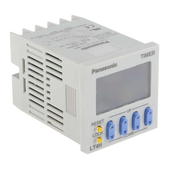
LT4H Timers
48
1.890
48
1.890
Pin type
Screw terminal type
RoHS Directive compatibility information
http://www.nais-e.com/
Product types
Time range
9.999 s (0.001 s~)
99.99 s (0.01 s~)
999.9 s (0.1 s~)
9999 s (1 s~)
99 min 59 s (1 s~)
999.9 min (0.1 min~)
99 h 59 min (1 min~)
999.9 h (0.1 h~)
* A rubber gasket (ATC18002) and a mounting frame (AT8-DA4) are included.
UL File No.: E122222
C-UL File No.: E122222
Features
1. Bright and Easy-to-Read Display
A brand new bright 2-color back light
LCD display. The easy-to-read screen in
any location makes checking and setting
procedures a cinch.
2. Simple Operation
Seesaw buttons make operating the unit
64.5
even easier than before.
2.539
3. Short Body of only 64.5 mm
mm
inch
inch
(screw terminal type) or 70.1 mm
2.760 inch
With a short body, it is easy to install in
even narrow control panels.
4. Conforms to IP66's Weather
Resistant Standards
The water-proof panel keeps out water
and dirt for reliable operation even in
poor environments.
Operating mode
Output
Relay
(1 c)
Power ON delay (1)
Power ON delay (2)
Signal ON delay
Signal OFF delay
Pulse One-shot
Pulse ON-delay
Signal Flicker
Totalizing ON-delay
(8 modes)
Transistor
(1 a)
All Rights Reserved © COPYRIGHT Matsushita Electric Works, Ltd.
DIN 48 SIZE
DIGITAL TIMER
2.539
(pin type)
Operating voltage
Power down insurance
100 to 240 V AC
24 V AC
12 to 24 V DC
100 to 240 V AC
24 V AC
12 to 24 V DC
LT4H/-L
Timers
5. Screw terminal (M3.5) and Pin
Types are Both Standard Options
The two terminal types are standard
options to support either front panel
installation or embedded installation.
6. Changeable Panel Cover
Also offers a black panel cover to meet
your design considerations.
7. Compliant with UL, c-UL and CE.
Terminal type
8 pins
11 pins
Screw terminal
8 pins
11 pins
Screw terminal
8 pins
11 pins
Screw terminal
Available
8 pins
11 pins
Screw terminal
8 pins
11 pins
Screw terminal
8 pins
11 pins
Screw terminal
Part number
LT4H8-AC240V
LT4H-AC240V
LT4H-AC240VS
LT4H8-AC24V
LT4H-AC24V
LT4H-AC24VS
LT4H8-DC24V
LT4H-DC24V
LT4H-DC24VS
LT4HT8-AC240V
LT4HT-AC240V
LT4HT-AC240VS
LT4HT8-AC24V
LT4HT-AC24V
LT4HT-AC24VS
LT4HT8-DC24V
LT4HT-DC24V
LT4HT-DC24VS
Advertisement
Table of Contents

Related Manuals for Panasonic LT4H/-L


Summary of Contents for Panasonic LT4H/-L
- Page 1 LT4H/-L DIN 48 SIZE DIGITAL TIMER Timers LT4H Timers UL File No.: E122222 C-UL File No.: E122222 Features 1. Bright and Easy-to-Read Display 5. Screw terminal (M3.5) and Pin A brand new bright 2-color back light Types are Both Standard Options LCD display.
- Page 2 LT4H/-L LT4H-L Timers UL File No.: E122222 C-UL File No.: E122222 Features 1. Economically priced in anticipation 4. Compliant with UL, c-UL and CE. of market needs. • Economically priced to provide excellent cost performance. 2. Display is a bright reflective-type LCD.
-
Page 3: Specifications
LT4H/-L Specifications Type Ralay output type Transistor output type Item AC type AC/DC type DC type AC type AC/DC type DC type 100 to 240 V AC, 24 V AC, 100 to 240 V AC, 24 V AC, Rated operating voltage... - Page 4 LT4H/-L Dimensions (units: mm inch) Tolerance: ±1.0 ±.039 • LT4H digital timer Screw terminal type Pin type (Flush mount) (Flush mount/Surface mount) 64.5 55.6 14.5 .217 2.539 .217 2.189 .571 1.890 TIMER 44.5 44.5 1.752 1.752 LOCK RESET LOCK LT4H DOWN .295...
- Page 5 LT4H/-L Setting the operation mode, time range, and time Setting procedure 1) Setting the operation mode and time range Set the operation mode and time range with the DIP switches on the side of the LT4H timer. Table 1: Setting the operation mode...
- Page 6 LT4H/-L Operation mode T: Set time t1, t2, t3, ta<T Operation type Explanation Time chart • Set the operation mode section of the DIP switches (no.’s 1, 2, and 3) on the side of the timer as shown. • Clears elapsed time value and starts time delay at power ON.
- Page 7 LT4H/-L T: Set time t1, t2, t3, ta<T Operation type Explanation Time chart • Set the operation mode section of the DIP switches (no.’s 1, 2, and 3) on the side of the timer as shown. • Clears elapsed time value at power ON.
- Page 8 LT4H-W LT4H-W DIN 48 SIZE DIGITAL TIMER Timers UL File No.: E122222 C-UL File No.: E122222 Features 1. Wide time range 5. Conforms to IP66’s Weather Resistant Standards The operation time range covers from 0.01 sec. to 9999 hours. The water-proof panel keeps out water The individual setting can be performed and dirt for reliable operation even in 1.890...
- Page 9 LT4H-W Part names (Subtraction elapsed DIP switches T1/T2 Operation display TIMER time display) Elapsed time display Display for change-over between T1/T2 settings Set time display Controlled output indicator LOCK Lock indicator Time units display RESET Reset switch Up keys SET/LOCK Set/Lock switch Down keys LT4H-W...
- Page 10 LT4H-W Applicable standard Safety standard EN61812-1 Pollution Degree 2/Overvoltage Category II (EMI)EN61000-6-4 Radiation interference electric field strength EN55011 Group1 ClassA Noise terminal voltage EN55011 Group1 ClassA (EMS)EN61000-6-2 Static discharge immunity EN61000-4-2 4 kV contact 8 kV air RF electromagnetic field immunity EN61000-4-3 10 V/m AM modulation (80 MHz to 1 GHz) 10 V/m pulse modulation (895 MHz to 905 MHz)
- Page 11 LT4H-W Terminal layouts and Wiring diagrams • 8-Pin type • 11-Pin type Relay output type Transistor output type Relay output type Transistor output type Start Reset N.C. Reset Start Start Start Reset N.C. N.O. Reset Stop Stop N.O. Lock Lock 1 11 1 11 Operating...
- Page 12 LT4H-W Setting the operation mode and time range Setting procedure 1) Setting the time range (Timer T /Timer T Set the time range with the DIP switches on the side of the LT4H-W timer. Table 1: Setting the time range (Timer T DIP switch Item DIP switch No.
- Page 13 LT4H-W OPERATION MODE PULSE : Pulse input INTEGRATION : Integrating input PULSE OFF-start/1 operation t <T <T INTEGRATION OFF-start/1 operation t <T <T ta+tb=T1 tc+td=T2 ta+tb=T1 tc+td=T2 te+tf=T1 tg+th=T2 Power Power supply supply Output Output T1 t2 tf tg Delayed Stop Stop one shot...
- Page 14 PRECAUTIONS IN USING THE LT4H SERIES 1. Terminal wiring If independent power circuitry must be Reset input 1) When wiring the terminals, refer to the used, keep the input contacts or transis- Start input Stop input terminal layout and wiring diagrams and tors separate from each other, as shown Lock be sure to perform the wiring properly...
- Page 15 PRECAUTIONS IN USING THE LT4H SERIES Once the wiring to be used is completely (2) Use the diode connected to the out- • Surge wave form [± (1.2 × 50) µs uni-polar full wave voltage] installed and prior to installing this timer, put transistor’s collector for absorbing confirm that there is complete insulation the reverse voltage from induced loads.
- Page 16 PRECAUTIONS IN USING THE LT4H SERIES 6) Long periods of continuous operation 7. Acquisition of CE marking 4) Please use a power supply that is pro- in the time-up completed condition (one Please abide by the conditions below tected by an overcurrent protection month or more) will result in the weaken- when using in applications that comply device which complies with the EN/IEC...