Table of Contents

Related Manuals for Canon CF-1


Summary of Contents for Canon CF-1
- Page 1 000_L-IE-5152E_CF-1.book Page 1 Monday, July 29, 2013 10:30 AM Digital Retinal Camera CF-1 Operation Manual Make sure you read this manual before using the instrument. Keep this manual in a safe place so that you can use it in the future.
- Page 2 Be sure to avoid having objects such as these, which affect this product, brought near the product. 5. In no event will Canon be liable for direct or indirect consequential damage arising out of the use of this product. Canon will not be liable for loss of image data for any reason.
-
Page 3: Safety Information
This instrument conforms to IEC 60601-1-2:2001/A1:2004 and IEC 60601-1-2:2007. For USA and Canada • When the CF-1 is going to be operated at a voltage of 240V in USA or Canada, be sure to connect the instrument to a center tapped voltage source. -
Page 4: Iso15004
000_L-IE-5152E_CF-1.book Page 4 Monday, July 29, 2013 10:30 AM Safety Information ISO15004 This report provides information about the hazard to the examinee’s eyes in compliance with ISO15004 (1997). 1. The spectral characteristics of radiant flux exiting from this instrument are as follows: Observation light at COLOR Observation light at RED FREE Observation light at FLUO... - Page 5 000_L-IE-5152E_CF-1.book Page 5 Monday, July 29, 2013 10:30 AM Safety Information According to the American Conference of Governmental Industrial Hygienist (ACGIH) - Threshold Limit Values for Chemical Substances and Physical Agents (1995 - 1996 edition), at photochemical radiances La and Lb of 80 [mW/cm²/sr], 3 minutes irradiation would cause the retinal exposure dose level to attain the recommended exposure limit.
-
Page 6: Emc (Electromagnetic Compatibility)
CF-1. 5. The CF-1 should not be used adjacent to or stacked with other equipment; if adjacent or stacked use is necessary, the CF-1 should be observed to verify normal operation in the... -
Page 7: Guidance And Manufacturer's Declaration For Emc Directive
Guidance and Manufacturer’s Declaration for EMC Directive Electromagnetic Emissions The CF-1 is intended for use in the electromagnetic environment specified below. The user of the CF-1 should assure that it is used in such an environment. Emission Test Compliance Electromagnetic Environment – Guidance The CF-1 uses RF energy only for its internal function. - Page 8 000_L-IE-5152E_CF-1.book Page 8 Monday, July 29, 2013 10:30 AM Safety Information Electromagnetic Immunity The CF-1 is intended for use in the electromagnetic environment specified below. The user of the CF-1 should assure that it is used in such an environment. IEC 60601 Test Compliance Electromagnetic Environment –...
- Page 9 RF transmitters, an electromagnetic site survey should be considered. If the measured field strength in the location where the CF-1 is used exceeds the applicable RF compliance level above, the CF-1 should be observed to verify normal operation. If abnormal performance is observed, additional measures may be necessary, such as reorienting or relocating the CF-1.
- Page 10 Safety Information Recommended Separation Distances The CF-1 is intended for use in an electromagnetic environment in which radiated RF distur- bances are controlled. The user of the CF-1 can help prevent electromagnetic interference by maintaining a minimum distance between portable and mobile RF communications equipment (transmitters) and the CF-1 as recommended below, according to the maximum output power of the communications equipment.
-
Page 11: General Safety Information
000_L-IE-5152E_CF-1.book Page 11 Monday, July 29, 2013 10:30 AM Safety Information General Safety Information Follow the safety instructions in this manual and all warnings and cautions printed on the warning labels. Ignoring such cautions or warnings while handling the product may result in injury or accident. Be sure to read and fully understand the manual before using this product. -
Page 12: Safety Precautions
Also, when other equipment is going to be connected to the instrument using WARNING the connector for interface, be sure that leakage current is within the tolerable value. For details, please contact your sales representative or local Canon dealer. Power Supply Only operate with the type of power supply indicated on the rating label. - Page 13 000_L-IE-5152E_CF-1.book Page 13 Monday, July 29, 2013 10:30 AM Safety Information Power Supply Securely plug in the power cable into the AC outlet. If contact failure occurs, or if dust or a metal object comes in contact with the WARNING exposed metal prong of the plug, fire or electric shock may result.
-
Page 14: Maintenance And Inspection
Should any of the following occur, immediately turn OFF the power of each instrument, unplug the power cable from the AC outlet, and contact your sales representative or local Canon dealer. • When there is smoke, an odd smell or abnormal sound. - Page 15 000_L-IE-5152E_CF-1.book Page 15 Monday, July 29, 2013 10:30 AM Safety Information Maintenance and Inspection The instrument must be repaired by a qualified engineer only. WARNING If it is not repaired properly, it may cause fire, electric shock, or accident. For safety reasons, be sure to inspect the instrument before using it. CAUTION Always take a test image to check that there is no foreign matter present that CAUTION...
-
Page 16: Labels And Markings On The Instrument
000_L-IE-5152E_CF-1.book Page 16 Monday, July 29, 2013 10:30 AM Safety Information Labels and Markings on the Instrument The CF-1 has a label on it. The label contents and its position are indicated below. For 110-120V Countries For 230-240V Countries -16-... -
Page 17: Table Of Contents
000_L-IE-5152E_CF-1.book Page 17 Monday, July 29, 2013 10:30 AM Contents Safety Information.................... 3 Regulations ....................3 ISO15004 ....................4 EMC (Electromagnetic Compatibility) ............6 Guidance and Manufacturer’s Declaration for EMC Directive ....7 General Safety Information ..............11 Labels and Markings on the Instrument ..........16 1. - Page 18 7.6.2 Removing the EOS Digital Camera ........54 7.7 Connecting the USB Cables ............56 7.8 Carrying the instrument ..............57 8. Service Information ..................58 9. Main Specifications ..................59 10. Components..................... 60 11. EN IEC60601-1-6:2010 Equipment Application Specification CF-1..........61 -18-...
-
Page 19: Features
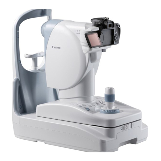
000_L-IE-5152E_CF-1.book Page 19 Monday, July 29, 2013 10:30 AM 1. Features The Canon CF-1 digital retinal camera is used to observe the retinas of patients’ eyes and take photographic images of them (in 4 modes: color, red-free, OPTION and fluorescein angiography). -
Page 20: Notes For Using The Instrument
000_L-IE-5152E_CF-1.book Page 20 Monday, July 29, 2013 10:30 AM 2. Notes for Using the Instrument Before Use • Take a daily test image to ensure that there is no foreign matter present that can affect image readings. • Check and clean the objective lens before taking an image, as any stains or scratches on it will appear as white spots. - Page 21 Federal law restricts this device to sale by or on the order of a licensed practitioner. Intended Use: CF-1 is intended to be used for taking digital images of the retina of human eye with a mydriatic. For European Union...
-
Page 22: Description
000_L-IE-5152E_CF-1.book Page 22 Monday, July 29, 2013 10:30 AM 3. Description 3.1 Main Unit Symbol Name Function Used to guide the patient’s eye and determine which area of the External eye fixation lamp eye to photograph. Head rest Holds the patient’s head in place. Forehead rest Place the patient’s forehead against this rest. - Page 23 000_L-IE-5152E_CF-1.book Page 23 Monday, July 29, 2013 10:30 AM 3. Description Symbol Name Function Viewfinder Use this when positioning and focusing on the patient’s eye. Digital camera cover Covers the terminal of the digital camera. Digital camera Takes fundus images (sold separately) Shutter release button Press this button to take an image.
-
Page 24: Operation Panel
000_L-IE-5152E_CF-1.book Page 24 Monday, July 29, 2013 10:30 AM 3. Description 3.2 Operation Panel Symbol Name Function Brightness adjuster Used for adjusting brightness in field of view for observation. The lamp for the selected photography mode turns ON. Mode indicator lamp COLOR and FLUO light up when the OPTION is selected. -
Page 25: Preparation
000_L-IE-5152E_CF-1.book Page 25 Monday, July 29, 2013 10:30 AM 4. Preparation Concerning the power-saving function The power-saving function is activated under the following circumstances: • When none of the switches on the operation panel have been operated for 10 or more minutes while power is supplied to the camera •... -
Page 26: Unlock The Stage Unit
000_L-IE-5152E_CF-1.book Page 26 Monday, July 29, 2013 10:30 AM 4. Preparation 4.2 Unlock the stage unit. If the stage unit is locked, press the stage unit lock button to release the lock. 4.3 Adjust the viewfinder. Note: Be sure to adjust the diopter of the viewfinder so it matches the diopter of the photographer’s eye. -
Page 27: Photography
For details on the control software operations, refer to the operating instructions of the control software. 5.1 Photography modes Four photography modes are available in the CF-1. The mode can be selected with the MODE switch on the control panel or with the control software. Photography mode... -
Page 28: Color Photography Mode
000_L-IE-5152E_CF-1.book Page 28 Monday, July 29, 2013 10:30 AM 5. Photography 5.2 Color photography mode Enter the study information into the computer. Enter the study information with the control software. Select color photography mode. Select COLOR with the MODE switch. Or select the photography mode with the control software. - Page 29 000_L-IE-5152E_CF-1.book Page 29 Monday, July 29, 2013 10:30 AM 5. Photography Align the camera’s main unit to the eye to be photographed. Do not put your fingers or hands between the sliding part and base of the stage unit or on the panning and tilting sliding parts. Similarly, do not allow patients to put their hands in these places.
- Page 30 000_L-IE-5152E_CF-1.book Page 30 Monday, July 29, 2013 10:30 AM 5. Photography The position where the working distance dots appear small is the optimum position. Working distance dots When the split lines are not visible Part of the split lines may not be visible if the pupil diameter is small. In this case, press the small pupil photography switch to turn ON the small pupil photography function (see page 39).
- Page 31 000_L-IE-5152E_CF-1.book Page 31 Monday, July 29, 2013 10:30 AM 5. Photography Focus on the patient’s eye. Turn the focus knob to focus the image. When using the focus indicator (see page 38), ensure that the split lines in the center are aligned into a single straight line.
- Page 32 000_L-IE-5152E_CF-1.book Page 32 Monday, July 29, 2013 10:30 AM 5. Photography Select the photography range. × 2 photography function (see page 38) is turned × ON and OFF each time the 2 switch is pressed. ×2 photography × When the 2 photography function is ON, the lamp range ×...
- Page 33 000_L-IE-5152E_CF-1.book Page 33 Monday, July 29, 2013 10:30 AM 5. Photography Concerning the adjustment of the flash intensity The flash intensity is already set to the standard level for each photography mode. To adjust the intensity, press the flash intensity switches. Each time one of these switches is pressed, the intensity is increased or reduced by steps of 0.3.
-
Page 34: Red-Free Photography Mode
000_L-IE-5152E_CF-1.book Page 34 Monday, July 29, 2013 10:30 AM 5. Photography 5.3 Red-free Photography Mode The steps with no explanation in the procedure below are the same as in the color photography mode. Refer to the procedure for the color photography mode (see page 28). Enter the study information into the computer. -
Page 35: Option Photography Mode
000_L-IE-5152E_CF-1.book Page 35 Monday, July 29, 2013 10:30 AM 5. Photography 5.4 OPTION Photography Mode In this mode, OPTION photography using the exciter filter for fluorescein angiography is possible. The control software must be set up in order to perform OPTION photography. For details on the settings, refer to the operating manual for the control software. -
Page 36: Fluorescein Angiography Mode
000_L-IE-5152E_CF-1.book Page 36 Monday, July 29, 2013 10:30 AM 5. Photography 5.5 Fluorescein Angiography Mode The steps with no explanation in the procedure below are the same as in the color photography mode. Refer to the procedure for the color photography mode (see page 28). Enter the study information into the computer. - Page 37 000_L-IE-5152E_CF-1.book Page 37 Monday, July 29, 2013 10:30 AM 5. Photography Start the timer. Press the TIMER/C switch as soon as the fluorescein medium is injected. The buzzer sounds each second, the lamp lights brightly and the elapsed time is displayed in the control software.
-
Page 38: Photography Auxiliary Functions
000_L-IE-5152E_CF-1.book Page 38 Monday, July 29, 2013 10:30 AM 6. Photography auxiliary functions 6.1 Using the focus indicator The focus indicator switch on the operation panel can be used to select whether or not to use the focus indicator. Focus indicator lamp When the focus indicator is being used, the focus indicator lamp lights brightly. -
Page 39: Small Pupil Photography Function
000_L-IE-5152E_CF-1.book Page 39 Monday, July 29, 2013 10:30 AM 6. Photography auxiliary functions 6.3 Small pupil photography function The small pupil photography function can be used in the color, red free or OPTION photography mode. Small pupil photography lamp To activate this function, press the small pupil photography switch on the operation panel. -
Page 40: Panning Function And Tilting Function
000_L-IE-5152E_CF-1.book Page 40 Monday, July 29, 2013 10:30 AM 6. Photography auxiliary functions 6.5 Panning function and tilting function 6.5.1 Panning function This function is used to take photographs of edges in the side- to-side direction. First, turn the panning lock knob to the position, and then adjust the angle of the digital retinal camera main unit in the side-to-side right direction. -
Page 41: Daily Inspection And Maintenance
If the inspection finds a fault, and you are unable to correct the problem, please contact your sales representative or local Canon dealer. It is recommended that you either copy the tables 7.1.1 and 7.1.2 on the following pages or create a separate checklist for recording the inspection results. -
Page 42: Before Turning On The Power
Remedy Check that the power cable is Contact your sales representative Pass/ Pass/ Pass/ not damaged and the covering or local Canon dealer if there is a Fail Fail Fail is not torn. problem. Check that the power cable is... -
Page 43: Turning On The Power
Remedy Check that the EOS digital Contact your sales representative camera is firmly attached and Pass/ Pass/ Pass/ or local Canon dealer if there is a the cables are connected Fail Fail Fail problem. correctly. 7.1.2 Turning ON the Power Always perform the inspections shown in the following sections to ensure proper function before use. - Page 44 Month Check that the chin rest Contact your sales representative moves smoothly up and down Pass/ Pass/ Pass/ or local Canon dealer if there is a when the CHIN REST switch Fail Fail Fail problem. is pressed. 7.1.2.2 Check Items on the Image...
-
Page 45: Before Calling A Service Technician
If performing the remedy still does not fix the problem, or the warning is still displayed, turn OFF the power, and contact your sales representative or local Canon dealer. Please be sure to describe the problem or warning message in detail. - Page 46 The split lines display lamp is Contact your sales representative or local burned out. Canon dealer. Turn the focus knob to focus so that the The split lines do not The diopter of the patient’s eye is cross-hair lines in the field of view and align.
- Page 47 000_L-IE-5152E_CF-1.book Page 47 Monday, July 29, 2013 10:30 AM 7. Daily Inspection and Maintenance Problem Cause Remedy The objective lens is dirty. Clean the lens (see page 48). White spots appear on the The patient’s eyelashes have Instruct the patient to open his or her eye photographed images.
-
Page 48: Cleaning And Disinfection
Use the procedure below to clean the objective lens when it is dirty. Please order the lens cleaning paper, lens cleaner, and blower from your sales representative or local Canon dealer. Turn ON the power of the main unit. Press the power switch to the I side. -
Page 49: Viewfinder
7. Daily Inspection and Maintenance Wipe off the objective lens. Gently wipe the lens with Canon-designated lens cleaning paper that has been wet with the Canon- designated lens cleaner. Starting from the center of the lens, wipe the lens in increasingly larger spirals toward the circumference. -
Page 50: Cover
000_L-IE-5152E_CF-1.book Page 50 Monday, July 29, 2013 10:30 AM 7. Daily Inspection and Maintenance 7.3.4 Cover When the instrument is going to be cleaned, be sure to turn OFF the power and unplug the power cable from the AC outlet. WARNING Never use alcohol, benzine, thinner or any other flammable cleaning agents. -
Page 51: Refilling The Chin Rest Paper
000_L-IE-5152E_CF-1.book Page 51 Monday, July 29, 2013 10:30 AM 7. Daily Inspection and Maintenance 7.4 Refilling the Chin Rest Paper Note: If the chin rest paper will not be used, be sure to disinfect the chin rest for each patient in the same manner as for the forehead rest. -
Page 52: Power Cable Connections
000_L-IE-5152E_CF-1.book Page 52 Monday, July 29, 2013 10:30 AM 7. Daily Inspection and Maintenance 7.5 Power Cable Connections Be sure to operate this instrument using the power supply described in the WARNING specifications. Otherwise, it may result in fire or electric shock. Be sure to turn OFF the power before plugging or unplugging the cables as indicated in this manual. -
Page 53: Installing And Removing The Eos Digital Camera
Mount the EOS digital camera to the main unit. Align the EF lens mount index of the EOS digital camera with the CF-1 positioning mark. Positioning mark EF lens mount index Fit the lens mount of the EOS digital camera into the camera mount and turn the camera unit clockwise until it clicks into place. -
Page 54: Removing The Eos Digital Camera
000_L-IE-5152E_CF-1.book Page 54 Monday, July 29, 2013 10:30 AM 7. Daily Inspection and Maintenance Attach the cable to the EOS digital camera. Open the terminal cover of the EOS digital camera and connect the respective cables to the digital terminal and remote control terminal. - Page 55 000_L-IE-5152E_CF-1.book Page 55 Monday, July 29, 2013 10:30 AM 7. Daily Inspection and Maintenance Remove the EOS digital camera. Turn the EOS digital camera counter-clockwise while holding down the lens release button on the EOS digital camera to detach the camera. Remove the DC coupler.
-
Page 56: Connecting The Usb Cables
• Cable with type AB connector plug supporting USB 2.0 Hi-Speed, maximum length of 3 meters For further details, contact your sales representative or local Canon dealer. Note: When connecting the USB cable, pass it underneath the cables of the camera main unit, and connect. -
Page 57: Carrying The Instrument
Note: If this product will be transported in an automobile or shipped a long distance, protective measures need to be taken against vibrations and shocks. Ask your sales representative or local Canon dealer for more information. Turn OFF the power of the retinal camera. -
Page 58: Service Information
These parts cannot be replaced by the user. If these parts are found to be worn out or to have deteriorated during daily or regular inspection, contact your sales representative or local Canon dealer for repair. • Halogen lamp for observation •... -
Page 59: Main Specifications
±5 D range Flash intensity Linked to photography mode Can be set manually Camera Canon EOS digital camera (sold separately) Eye fixation lamp External eye fixation lamp Internal Eye Fixation Target (sold separately) Working range Stage horizontal movement 110 mm side to side, 65 mm front and back... -
Page 60: Components
Camera mount cap ........................1 Digital camera cover......................... 1 Dust cover..........................1 CD-ROM (Retinal imaging control software MYD) ............... 1 Operation manual (CF-1/control software) ................1 each DICOM conformance statement....................1 Software license agreement ...................... 1 Warranty card (for USA model only) ..................1 WEEE directive leaflet (for EU model only) ................ -
Page 61: En Iec60601-1-6:2010
000_L-IE-5152E_CF-1.book Page 61 Monday, July 29, 2013 10:30 AM 11. EN IEC60601-1-6:2010 Equipment Application Specification CF-1 Medical Purpose a) Device name Retinal camera b) Objective Observation, photographing, and recording of the ocular fundus by passing through the pupil without making contact with the examined eye and providing fundus image information for diagnosis. - Page 62 000_L-IE-5152E_CF-1.book Page 62 Monday, July 29, 2013 10:30 AM -62-...
- Page 63 000_L-IE-5152E_CF-1.book Page 63 Monday, July 29, 2013 10:30 AM...
- Page 64 CANON EUROPA N.V. Medical Products Division Bovenkerkerweg 59, 1185 XB Amstelveen, The Netherlands Telephone: (31)-20-545-8926 CANON SINGAPORE PTE. LTD. Medical Equipment Products Division 1 Harbour Front Avenue, #04-01 Keppel Bay Tower, Singapore 098632 Telephone: (65)-6799-8888 CANON AUSTRALIA PTY. LTD. Optical Products Division 1 Thomas Holt Drive, North Ryde, Sydney N.S.W.