Table of Contents
Advertisement
Quick Links
Installation Guide and Operating Manual
Model SS4-AUV/-AUV2 Ultraviolet (UV) Digital Electro-Optical Fire Detector
Installation Guide and Operating Manual
MAN0927_V3_1510-005_Rev H_06-13
Fire Sentry Model SS4-AUV/-AUV2
Ultraviolet (UV) Digital Electro-Optical Fire Detectors
STAND-ALONE RELAY MODE or 4-20 mA Output Option
i
Advertisement
Table of Contents

Related Manuals for Honeywell Fire Sentry SS4-AUV


Summary of Contents for Honeywell Fire Sentry SS4-AUV
- Page 1 Installation Guide and Operating Manual Model SS4-AUV/-AUV2 Ultraviolet (UV) Digital Electro-Optical Fire Detector Installation Guide and Operating Manual MAN0927_V3_1510-005_Rev H_06-13 Fire Sentry Model SS4-AUV/-AUV2 Ultraviolet (UV) Digital Electro-Optical Fire Detectors STAND-ALONE RELAY MODE or 4-20 mA Output Option...
-
Page 2: Table Of Contents
Configuring the Detector Module........................7 2.2.4 Wiring the Detector Module..........................7 2.2.5 Wiring the SS4-AUV/-AUV2 Detector for 4 or 20 mA Current Mode Operation (Optional) ........8 2.2.6 Wiring the Detector Relays ..........................9 2.2.7 Replacing the Detector Module in the Enclosure..................... 9 Enclosure Installation (optional) ......................... -
Page 3: Approvals
SRL-BIT (Built In Test) for optical “through the lens” of both the sensors and lens. The Model SS4-AUV/-AUV2 Ultraviolet Fire Detector has sensitivity to Type A, B, and C flaming fires, false alarm immunity, and an alarm range between 15 and 60 ft. to a one square foot gasoline pan fire, with a 120-degree (±... -
Page 4: Applications
Verification relay: N.O. and N.C. contacts (Adjustable time from 0 to 30 seconds) Fault relay: N.O. and N.C. contacts 1.1.3 Applications Applications of the Model SS4-AUV/-AUV2 Detectors include warehouses, aircraft hangars, petrochemical facilities, Gas turbines, and Power plants, among others. -
Page 5: Detector Locations
NOTE: The Fault relay is not available when the Detector is wired to the FS2000 System. FS2000 System Operation For FS2000 System operation, the Model SS4-AUV/-AUV2 Fire and Fault signals are sent digitally to the FS2000 System Controller using the four wire FS2000 FireBus. The FireBus provides 24 Volt DC power for the Detector and RS-485 digital communication (Refer to Fire Sentry document MN0003: "FS2000... -
Page 6: Overview
1.4.1 Model SS4-AUV/-AUV2 Detector Version SS4-AUV: There are two (2) LEDs on the Model SS4-AUV Detector that indicate the state of the Detector. During normal operation both LEDs will blink every 10 seconds. If the Detector alarms to a fire, it energizes the Fire relay and turns on both LEDs in the following sequence. -
Page 7: Testing
The Factory setting for the SS4-AUV is Latching and the SS4-AUV2 is Non-Latching. If the SS4-AUV or SS4-AUV2 Latching mode is selected, the Fire or Verify Relay will energize and Red LEDs will remain illuminated until the Detector power is cycled (power is turned off then on). -
Page 8: Man0927_V3_1510-005_Rev H
Power Supply Considerations The Model SS4-AUV/-AUV2 Detector uses 24 Volts DC at a maximum current of 50 mA (with the 4-20 mA option the maximum supply current is 70 mA). Make sure that the Panel's power supply can handle the load current of the total number of Detectors connected to it. -
Page 9: Removing Detector From Its Enclosure
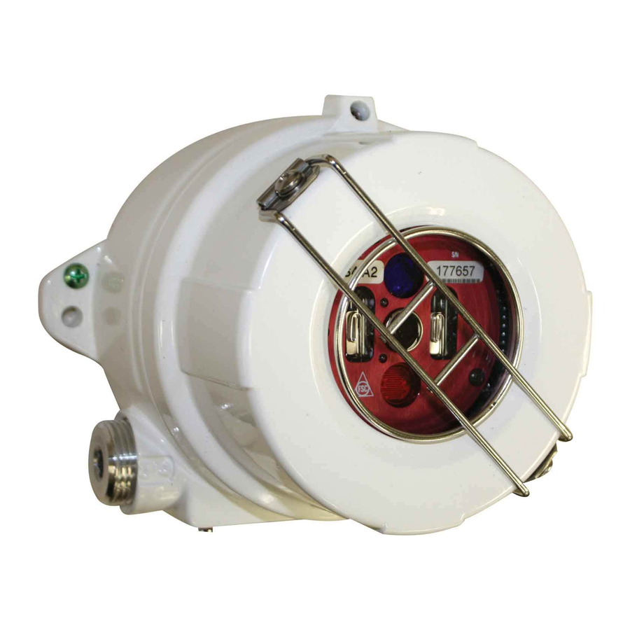
Model SS4-AUV/-AUV2 Ultraviolet (UV) Digital Electro-Optical Fire Detector Installation Guide and Operating Manual MAN0927_V3_1510-005_Rev H_06-13 2.2.2 Removing Detector from its Enclosure. a. With electrical power off (verify that electrical power is off by making sure that the Detector's LEDs do not blink for at least 15 seconds), loosen the Allen-head screw at the base of the metal enclosure top lens cover. -
Page 10: Wiring The Ss4-Auv/-Auv2 Detector For 4 Or 20 Ma Current Mode Operation (Optional)
MAN0927_V3_1510-005_Rev H_06-13 2.2.5 Wiring the SS4-AUV/-AUV2 Detector for 4 or 20 mA Current Mode Operation (Optional) For applications requiring a 4-20 mA analog output, order the Detector with the Optional 4-20 mA Module Assembly, P/N MA420-4. The module must be Factory installed and certified along with the Detector. -
Page 11: Wiring The Detector Relays
Model SS4-AUV/-AUV2 Ultraviolet (UV) Digital Electro-Optical Fire Detector Installation Guide and Operating Manual MAN0927_V3_1510-005_Rev H_06-13 2.2.6 Wiring the Detector Relays a. Insert relay cables into the Detector enclosure base through one of the conduit openings. Refer to Figure 6. b. Fire Alarm Relay - Connect wires for Fire Alarm to the appropriate J4 terminals of the Detector. - Page 12 Model SS4-AUV/-AUV2 Ultraviolet (UV) Digital Electro-Optical Fire Detector Installation Guide and Operating Manual MAN0927_V3_1510-005_Rev H_06-13 2.95 2.00 4.26 4.86 0.295 Dia. 4.7” approx. Figure 4: Model SM2 Swivel Mount Figure 5: Model SM4 Stainless Steel Swivel Mount...
- Page 13 Model SS4-AUV/-AUV2 Ultraviolet (UV) Digital Electro-Optical Fire Detector Installation Guide and Operating Manual MAN0927_V3_1510-005_Rev H_06-13 1.50 4.38 2.40 0.67 2.09 1.10 4.66 Figure 6: Model SS4-AUV/-AUV2 Detector Enclosure - Side View Figure 7: Model SS4-AUV/-AUV2 Detector Enclosure - Rear View...
-
Page 14: Section 3 Troubleshooting And Maintenance
Cleaning Windowed Enclosures and Detectors The optical window (lens) of the Model SS4-AUV/-AUV2 Detector should be cleaned periodically on a regular maintenance schedule. For clean area applications, perhaps monthly cleaning schedule will be sufficient. For extremely contaminated application environments, such as truck filling stations with presence of black carboneous smoke, daily cleaning schedule may be necessary. -
Page 15: Detector Repair
USER SERVICEABLE PARTS IN A ETECTOR MODULE If the Model SS4-AUV/-AUV2 Module must be shipped back to the factory for repair, it MUST be packed in static protective material. If not available, the Module should be carefully wrapped with aluminum foil. An RMA (Return Material Authorization) is required for all returns to the factory. -
Page 16: Detector Pinout Data
Model SS4-AUV/-AUV2 Ultraviolet (UV) Digital Electro-Optical Fire Detector Installation Guide and Operating Manual MAN0927_V3_1510-005_Rev H_06-13 DETECTOR PINOUT DATA TABLE 1: Stand-Alone Model SS4-AUV/-AUV2 Detector Connectors - Pinouts J1: DETECTOR INPUT POWER DC Return ( - ) 2 and 3: RS-485 Connection to an optional interface unit for viewing FirePic and TriMode Plot. -
Page 17: Verification Time
Latching mode. If Verify is enabled then when the Verify Relay energizes it will remain energized until the Detector is reset. If Verify is disabled then when the Fire Relay energizes it will remain energized until the Detector is reset. The SS4-AUV Factory setting is Latching DIP SWITCH... -
Page 18: Section 4 Optional Accessories
Model SS4-AUV/-AUV2 Ultraviolet (UV) Digital Electro-Optical Fire Detector Installation Guide and Operating Manual MAN0927_V3_1510-005_Rev H_06-13 SECTION 4 OPTIONAL ACCESSORIES Air Shield for Applications in Contaminated Environment (Part No. DASA1-P) For installation in areas with high levels of airborne contaminants the Detector Air Shield should be mounted to the Flame Detector housing. -
Page 19: Index
Model SS4-AUV/-AUV2 Ultraviolet (UV) Digital Electro-Optical Fire Detector Installation Guide and Operating Manual MAN0927_V3_1510-005_Rev H_06-13 INDEX Cleaning Products ............12 Installation ................. 5 Conduit ................5 Conduit ................5 Detector Detector................. 5 Cleaning ..............11 Enclosure ..............8 Enclosure ..............8 Precautions .............. - Page 20 Model SS4-AUV/-AUV2 Ultraviolet (UV) Digital Electro-Optical Fire Detector Installation Guide and Operating Manual MAN0927_V3_1510-005_Rev H_06-13 www.honeywellanalytics.com Contact Honeywell Analytics: Europe, Middle East, Africa, India Life Safety Distribution AG Javastrasse 2 8604 Hegnau Switzerland Tel: +41 (0)44 943 4300 Fax: +41 (0)44 943 439 India Tel: +91 124 4752700 gasdetection@honeywell.com...