Table of Contents
Advertisement
Quick Links
Advertisement
Table of Contents

Related Manuals for GE CC-SCSTAT


Summary of Contents for GE CC-SCSTAT
-
Page 1: Installation Manual
SmartCommand Thermostat Installation Manual... - Page 2 Document number/revision: 1060018A (July 2007). Disclaimer The information in this document is subject to change without notice. GE Security (“GE”) assumes no responsibility for inaccuracies or omissions and specifically disclaims any liabilities, losses, or risks, personal or otherwise, incurred as a consequence, directly or indirectly, of the use or application of any of the contents of this document.
-
Page 3: Table Of Contents
Thermostat information screen ........ - Page 4 SmartCommand Thermostat Installation Manual Serial communication test ................32 HVAC system testing .
-
Page 5: Preface
Preface This is the GE SmartCommand Thermostat Installation Manual for model CC-SCSTAT. This document includes an overview of the product and detailed instructions explaining: • how to install; and • how to operate the thermostat. There is also information describing how to contact technical support if you have questions or concerns. -
Page 6: Product Overview
Installation Manual Product overview The SmartCommand thermostat (model CC-SCSTAT) provides typical thermostat functions as well as the capability to send and receive information via serial communications. This capability allows the thermostat’s setpoint, mode, and fan operation to be changed remotely. In addition, the remote systems can request status of the thermostat’s temperature, setpoints, modes, and other system information. - Page 7 You can disable the Minimized screen if desired. Note: You can press any button when the Minimized screen is displayed to restore and display the Thermostat control screen. Menu selection screen. Press the Menu button on the Thermostat control screen to access the screen on page 7.
-
Page 8: Thermostat Control Screen
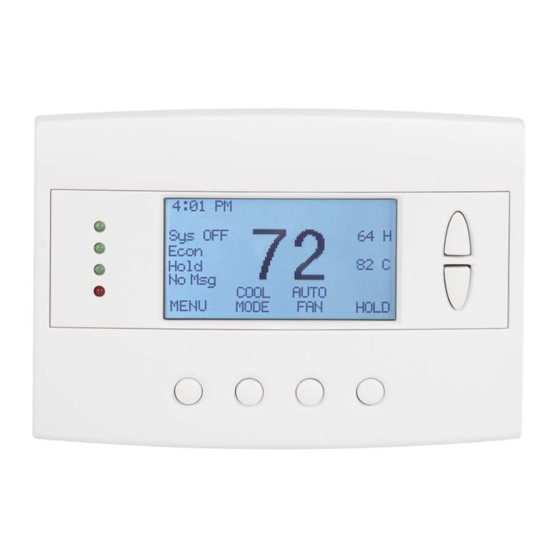
SmartCommand Thermostat Installation Manual Thermostat control screen The Thermostat control screen (Figure 2) is the default display screen normally displayed on the WDU. Figure 2. Thermostat control screen Display Temperature display The WDU will normally display the current temperature from the internal digital temperature sensor or a remote sensor. -
Page 9: Up And Down Buttons
Menu button The Menu button changes the screen display to the Main menu screen that shows other functions available on the thermostat. These are dynamic and can change with the version of the thermostat you have, but the standard ones include: •... -
Page 10: Run/Hold Button
The Run/Hold button controls the automatic schedule operation. In hold mode, the current temperature is maintained until changed by manual or remote network command. In the run mode, the schedule loaded into the thermostat is activated and setpoints will change according to the schedule and the time and day of the week. -
Page 11: Main Menu Screen
Main menu screen The thermostat has a menu tree that can be accessed by pressing the Menu button on the main Thermostat control screen. Various configurations of the unit can have different screen contents. The first screen that will display is the Main menu screen (Figure 3). This is a list of the other menus or functions that you can access. -
Page 12: Messages Screen
Note: New messages will turn on and flash the red message LED and mail icon in the main Thermostat control screen. Viewing messages makes them old and turns off the indicators. If you view some, but not all new messages, the new message notification LED and icon will stay on. -
Page 13: Schedule Setup Screen
4 by 7 schedule. Four times a day can be selected for heating and cooling setpoints. Each day of the week can have a different schedule. Groups of days can be copied with the same schedule. When the thermostat is set to run mode, the schedule will be executed daily, with the setpoints being changed as per that day’s schedule... -
Page 14: Heat And Cool Schedule Screen
SmartCommand Thermostat Installation Manual Heat and cool schedule screen When you select the Heat and cool schedule menu item, the Heat and cool schedule screen (Figure 6) opens and the schedule for the current day will be displayed. Use the scroll buttons to highlight the data to be modified. -
Page 15: Copy Schedule Screen
Copy schedule screen The Copy schedule screen (Figure 7) is a sub screen of the Copy schedule screen allows you to copy a day’s schedule to another day or group of days. To copy a day’s schedule, do the following: 1. -
Page 16: User Settings Screen
Installation Manual User settings screen The User settings screen (Figure 8) allows you to set or change various user options of the thermostat such as the clock, minimized screen timeout, Fahrenheit/Centigrade mode, sensor calibration, and backlight settings. Figure 8. User settings screen Screen options include: Set clock. -
Page 17: Set Clock Screen
3. Press Set to set the time and return to the main Menu screen or wait for the screen to timeout. Note: If the clock has been reset by an extended power outage, the clock display on the Thermostat control screen will be blinking. Pressing Menu button will take you directly to this screen to set the clock. -
Page 18: Sensor Calibration Screen
You can change the temperature calibration by ± 7 degrees. When the Sensor calibration screen is selected it will show the internal and all detected remote sensors. Each sensor found will show the current temperature and the current number of degrees of offset being applied. -
Page 19: Backlight Display Screen
Backlight display screen The Backlight display screen (Figure 11) is a sub screen of the User settings screen. The Backlight display screen allows you to set the backlight on and off brightness levels and contrast. Figure 11. Backlight display screen Screen options include: Backlight timeout. -
Page 20: Thermostat Information Screen
You will see a Fan type setting for standard systems or a Changeover setting for HP systems. Network address setting. RS485 network address, 1 to 254 (default 1). Figure 12. Thermostat information screen Thermostat information screen has one navigation button, the Done button. Press Done to return to settings screen on page 12. -
Page 21: Installer Settings Screen
Installer settings screen (Figure 13) appears. The Installer settings screen displays the current internal settings of the thermostat. You can view and change the settings from this screen. Scroll to the desired function and press Plus (+) or Minus (-) to change the value. - Page 22 Service mode submenu: Y or N (default N). Use this setting to turn on the service mode. When the service mode is on (Y), it sets the thermostat to a test mode with short delays. All routine and staging delays are reduced to 15 seconds to speed up system checkout and testing.
- Page 23 Messaging enable: Y or N (default N). Enable (Y) or disable (N) the network messaging function. If you intend to use the messaging capability of the thermostat, you must enable it here by setting it to Y. Messages will then appear as a menu item in the main Menu screen and you will be able to receive and browse through the messages.
-
Page 24: Installation Overview
SmartCommand Thermostat Installation Manual Installation overview Before you remove an existing thermostat and install the SmartCommand thermostat, follow these guidelines: • Record existing wiring information. • Do the bench test. • Check WDU wiring before applying power to the control unit. -
Page 25: Freeze Protection
In cold climates that require the heating system to be used for building freeze protection, a mechanical backup freeze protection device must be installed on the heating system. This can be a simple mechanical heating thermostat or a preset thermoswitch installed in the heated area (Figure 15). Figure 15. Freeze protection... -
Page 26: Wall Display Unit Installation
Category 5 wiring is preferred, but not required. In retrofit applications, the existing 18 Ga thermostat wiring (at least four wires) is adequate and usually will work without problems. However, such nontwisted wiring can be subject to interference due to adjacent in-wall high voltage wiring. -
Page 27: Control Unit Installation
Electrically, the control unit looks like a standard thermostat to your HVAC system. All connections to the HVAC system are made at the normal thermostat connections on the HVAC unit. Refer to your HVAC system’s documentation for specific information on its thermostat connections and set up requirements. You will need to know the following: HVAC system type. -
Page 28: Hvac System Wiring
Standard HVAC system wiring Figure 18 shows the wiring diagram for a standard gas or electric HVAC system. Wiring colors are typical thermostat wiring color codes. Note: For typical central heating/cooling systems, leave jumper JP1 installed. If you have separate heating and cooling system transformers, cut jumper JP1. - Page 29 For standard HVAC systems, follow these guidelines: Single-stage systems. Use W1 for heating stage 1, and Y1 for cooling stage 1. Two-stage heating systems. Use W1 for stage 1, and W2 for stage 2 heating. Two-stage cooling systems. Use Y1 for stage 1 and Y2 for stage 2 cooling. HVAC system 24 VAC transformer If you have an integrated heating and cooling system with a single transformer, do not cut jumper JP1.
-
Page 30: Heat Pump Hvac System Wiring
SmartCommand Thermostat Installation Manual Heat pump HVAC system wiring Figure 19 shows the wiring diagram for a heat pump HVAC system. Wire colors are typical thermostat color codes. Note: Do not cut JP1 for heat pump systems. RC and RH are common for heat pumps. -
Page 31: Dip Switches
For heat pump HVAC systems, follow these guidelines: Single-stage compressor systems. Use Y1 for stage 1 heating/cooling, and W1 for stage 2 heating (heat strips). Two-stage compressor systems. Use Y1 for stage 1, Y2 for stage 2 heating/cooling, and W1 for stage 3 heating (heat strips). -
Page 32: Control Unit Connection
SmartCommand Thermostat Installation Manual Control unit connection The control unit requires 24 VAC power from the HVAC system it is controlling. Connect the 24 VAC Common (blue wire/terminal) and 24 VAC R (red wire/terminal) from the HVAC system to the control unit’s HVAC system terminal block J4’s 24V Com and 24V RH (or 24V RC) terminals. -
Page 33: Serial Communication
This is necessary for RS485 half-duplex devices to use send data control for automatic flow control. RS485 address You can check the network address setting of the thermostat by pressing Menu to open the main Menu screen. Scroll down to the Thermostat info menu item and press Select. The will show the current network address of the thermostat. - Page 34 SmartCommand Thermostat Installation Manual RS485 protocol The thermostat has a robust serial protocol. It is based on a simple ASCII message format as described in the Serial Communications Protocol manual, DCN: 150-00225. Note: Not all of the commands/variables defined in the protocol document are applicable to the SmartCommand thermostat, check Section 8 of the protocol manual for details.
-
Page 35: System Checklist
System checklist We strongly recommend that you hook-up and run a simple bench test before installing the thermostat. Not only will this save you time in system checkout, but will also make you familiar with the thermostat’s operation. Thermostat bench test To bench test the thermostat, do the following: 1. -
Page 36: Serial Communication Test
SmartCommand Thermostat Installation Manual Serial communication test Connect the thermostat to a PC via an RS232/485 converter to a PC serial com port. Note: Any RS232 to RS485 adapter used with SmartCommand serial thermostats must have automatic send data control. -
Page 37: Hvac System Testing
Note: The HVAC system and thermostat connection voltage is 24 VAC. This is a safe voltage to work with, but be careful to avoid shorting the 24 VAC common (C) and 24 VAC return (R) terminals. This may blow a fuse in the HVAC system. - Page 38 Standard HVAC system quick test You can do a quick test of the HVAC system by shorting across the appropriate terminals on the HVAC system’s thermostat connector. Use a short 6-in. wire to connect across the terminals shown in Table 1. Table 1.
-
Page 39: Control Unit Wiring
Control unit wiring Figure 21 shows the control unit wired to a wall display unit and the HVAC system. Wire colors are typical thermostat wiring colors. The fuse is a mini ATO 2 amp. Note: For heat pump HVAC systems, the orange wire (O) is the changeover valve. - Page 40 SmartCommand Thermostat Installation Manual DIP switch SW1 settings White indicates a switch is in the On position. Set the DIP switches as follows: SW1-S1. HVAC system type selection. Standard or heat pump. Set S1 to Off (STD) for gas/electric systems (default setting).
-
Page 41: Serial Network Command And Variable List
Set heat setpoint Set variable number x Time Set time Request status message 1: Thermostat data (temperature, setpoints, modes) Request status message 2: HVAC operation data (heating/cooling/fan status) Request status message 3: Temperature data only Request status message 4: Setpoint data only... -
Page 42: Network Variables
SmartCommand Thermostat Installation Manual Network variables Table 4 shows the network variables for use with the system variable, SVx command. Table 4. Network variables Variable number Name System type Fan type Changeover type C/F type Network address Display lock H delta stage 1 on... -
Page 43: Contacting Technical Support
Many GE Security documents are provided as PDFs (portable document format). To read these documents, you will need Adobe Acrobat Reader, which can be downloaded free from Adobe’s website at www.adobe.com. - Page 44 SmartCommand Thermostat Installation Manual...