Table of Contents
Advertisement
Advertisement
Table of Contents

Related Manuals for Craftsman 82141


Summary of Contents for Craftsman 82141
-
Page 1: Digital Multimeter
Owner's Manual Digital MultiMeter Model No. 82141 • Safety CAUTION: Read, understand and • Operation follow Safety Rules and Operating • Maintenance Instructions in this manual before using this product. • Español © Sears, Roebuck and Co., Hoffman Estates, IL 60179 U.S.A. -
Page 2: Table Of Contents
TABLE OF CONTENTS Page Warranty Safety Instructions Safety Symbols Control and Jacks Symbols and Annunciators Specifications Battery Installation Operating Instructions DC Voltage Measurements AC Voltage Measurements DC Current Measurements AC Current Measurements Resistance Measurements Continuity Check Diode Test Battery Test Maintenance Replacing Batteries Replacing Fuses... -
Page 3: Warranty
ONE YEAR FULL WARRANTY ON CRAFTSMAN MANUAL RANGING MULTIMETER If this CRAFTSMAN Manual Ranging MultiMeter fails to give complete satisfaction within one year from the date of purchase, RETURN IT TO THE NEAREST SEARS STORE OR OTHER CRAFTSMAN OUTLET IN THE UNITED STATES, and Sears will replace it, free of charge. -
Page 4: Safety Instructions
SAFETY INSTRUCTIONS This meter has been designed for safe use, but must be operated with caution. The rules listed below must be carefully followed for safe operation. NEVER apply voltage or current to the meter that exceeds the specified maximum: Input Limits Function Maximum Input... -
Page 5: Safety Symbols
SAFETY SYMBOLS This symbol adjacent to another symbol, terminal or operating device indicates that the operator must refer to an explanation in the Operating Instructions to avoid personal injury or damage to the meter. This WARNING symbol indicates a potentially WARNING hazardous situation, which if not avoided, could result in death or serious injury. -
Page 6: Control And Jacks
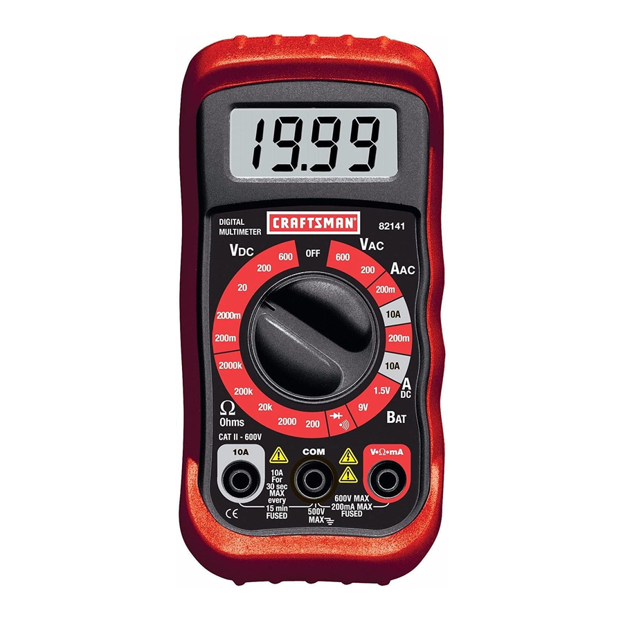
CONTROLS AND JACKS LCD Display Function switch COM jack 10A jack Positive jack Note: Tilt stand, fuse and battery compartment are on rear of unit. SYMBOLS AND ANNUNCIATORS •))) Continuity Diode test milli ( volts, amps) kilo (ohms) Ω ohms volts direct current volts alternating current amps direct current... -
Page 7: Specifications
SPECIFICATIONS Function Range Resolution Accuracy DC Voltage 200mV 0.1mV (V DC) 2000mV ±(0.5% reading + 2 digits) 0.01V 200V 0.1V 600V ±(1.5% reading + 5 digits AC Voltage 200V 0.1V (V AC) 600V (50/60Hz) ±(1.2% reading + 2 digits) DC Current 200mA 100µA (A DC) - Page 8 SPECIFICATIONS Test current of 1mA maximum, open circuit Diode Test voltage 2.8V DC typical Audible signal will sound if the resistance is less Continuity Check than approximately 30Ω 9V (6mA); 1.5V (100mA) Battery Test current >1MΩ Input Impedance 45Hz to 450Hz ACV Bandwidth 200mV DCA voltage drop...
-
Page 9: Battery Installation
BATTERY INSTALLATION WARNING: To avoid electric shock, disconnect the test leads from any source of voltage before removing the battery door. 1. Disconnect the test leads from the meter. 2. Remove the protective rubber holster (if installed). 3. Open the battery door by loosening the screw using a Phillips head screwdriver. -
Page 10: Operating Instructions
OPERATING INSTRUCTIONS WARNING: Risk of electrocution. High-voltage circuits, both AC and DC, are very dangerous and should be measured with great care. 1. ALWAYS turn the function switch to the OFF position when the meter is not in use. 2. If “1” appears in the display during a measurement, the value exceeds the range you have selected. -
Page 11: Ac Voltage Measurements
AC VOLTAGE MEASUREMENTS WARNING: Risk of Electrocution. The probe tips may not be long enough to contact the live parts inside some 240V outlets for appliances because the contacts are recessed deep in the outlets. As a result, the reading may show 0 volts when the outlet actually has voltage on it. -
Page 12: Dc Current Measurements
DC CURRENT MEASUREMENTS CAUTION: Do not make current measurements on the 10A scale for longer than 30 seconds. Exceeding 30 seconds may cause damage to the meter and/or the test leads. 1. Insert the black test lead banana plug into the negative (COM) jack. -
Page 13: Ac Current Measurements
AC CURRENT MEASUREMENTS CAUTION: Do not make current measurements on the 10A scale for longer than 30 seconds. Exceeding 30 seconds may cause damage to the meter and/or the test leads. 1. Insert the black test lead banana plug into the negative (COM) jack. -
Page 14: Resistance Measurements
RESISTANCE MEASUREMENTS WARNING: To avoid electric shock, disconnect power to the unit under test and discharge all capacitors before taking any resistance measurements. Remove the batteries and unplug the line cords. 1. Set the function switch to the highest Ω position. 2. -
Page 15: Diode Test
DIODE TEST 1. Insert the black test lead banana plug into the negative COM jack and the red test lead banana plug into the positive diode jack. 2. Turn the function switch to the / •))) position. 3. Touch the test probes to the diode under test. Forward voltage will indicate 400 to 700mV. -
Page 16: Maintenance
MAINTENANCE WARNING: To avoid electric shock, disconnect the test leads from any source of voltage before removing the back cover or the battery or fuse doors. WARNING: To avoid electric shock, do not operate your meter until the battery and fuse doors are in place and fastened securely. This MultiMeter is designed to provide years of dependable service, if the following care instructions are performed: 1. -
Page 17: Replacing Batteries
REPLACING BATTERIES WARNING: To avoid electric shock, disconnect the test leads from any source of voltage before removing the battery door. 1. When the batteries become exhausted or drop below the operating voltage, “ ” will appear in the lower left corner of the LCD display. The batteries should be replaced. -
Page 18: Troubleshooting
Description 82374 Fuse kit 93894 9V battery 82378 Set of black and red Test Leads 82141-DB Replacement battery door 82141-DF Replacement fuse door 82141-CS Rear cover screws For replacement parts shipped directly to your home Call 9 am – 5 pm Eastern Time, M - F...