Table of Contents
Advertisement
Advertisement
Table of Contents

Related Manuals for Craftsman 82170


Summary of Contents for Craftsman 82170
-
Page 1: Digital Multimeter
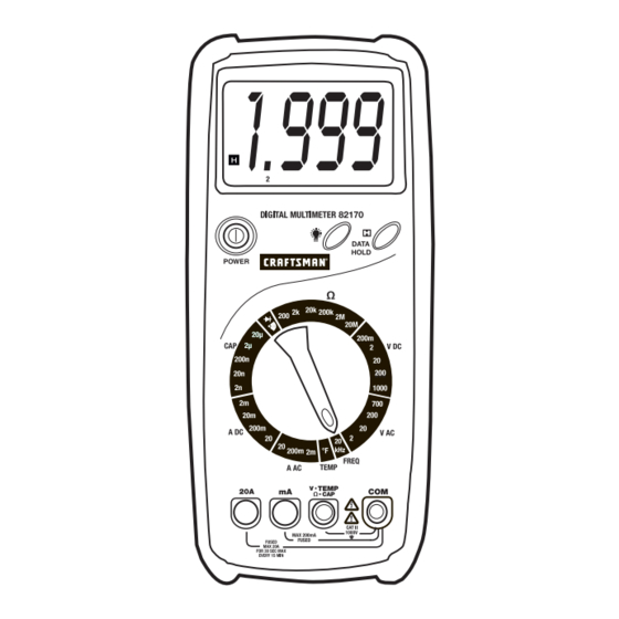
Owner's Manual Digital MultiMeter Model No. 82170 • Safety CAUTION: Read, understand and • Operation follow Safety Rules and Operating Instructions in this manual before • Maintenance using this product. • Español Sears, Roebuck and Co., Hoffman Estates, IL 60179 www.craftsman.com... -
Page 2: Table Of Contents
TABLE OF CONTENTS Page Warranty Safety Instructions Safety Symbols Control and Jacks Symbols and Annunciators Specifications Battery Installation Operating Instructions Data Hold Backlight Range Indicator Safety Shutters DC Voltage Measurements AC Voltage Measurements DC Current Measurements AC Current Measurements Resistance Measurements Continuity Check Diode Test Frequency Measurements... -
Page 3: Warranty
ONE YEAR FULL WARRANTY ON CRAFTSMAN MANUAL RANGING MULTIMETER If this CRAFTSMAN Manual Ranging MultiMeter fails to give complete satisfaction within one year from the date of purchase, RETURN IT TO THE NEAREST SEARS STORE OR OTHER CRAFTSMAN OUTLET IN THE UNITED STATES, and Sears will replace it, free of charge. -
Page 4: Safety Instructions
SAFETY INSTRUCTIONS This meter has been designed for safe use, but must be operated with caution. The rules listed below must be carefully followed for safe operation. NEVER apply voltage or current to the meter that exceeds the specified maximum: Input Limits Function Maximum Input... -
Page 5: Safety Symbols
SAFETY SYMBOLS This symbol adjacent to another symbol, terminal or operating device indicates that the operator must refer to an explanation in the Operating Instructions to avoid personal injury or damage to the meter. This WARNING symbol indicates a potentially WARNING hazardous situation, which if not avoided, could result in death or serious injury. -
Page 6: Symbols And Annunciators
SYMBOLS AND ANNUNCIATORS Continuity Low Battery Diode Data Hold Alternating Current or Voltage Direct Current or Voltage SPECIFICATIONS Function Range Resolution Accuracy ±(0.5% reading + 1 digit) DC Voltage 200mV 0.1mV ±(0.5% reading + 3 digits) (V DC) 10mV 200V 100mV ±(0.8% reading + 3 digits) 1000V... - Page 7 SPECIFICATIONS Function Range Resolution Accuracy ±(4.0% reading + 3 digits) Capacitance 20nF 10pF 200nF 0.1nF 2µF 10nF 20µF ±(1.5% reading + 10 digits) Frequency 20kHz 10Hz Sensitivity: 200mVac RMS to 10Vac RMS ±(5.0% reading + 5 digits) Temperature 0 to 32°F 1°F ±(1.0% reading + 3 digits) 32 to 750°F...
-
Page 8: Battery Installation
SPECIFICATIONS Batteries Requires one 9V NEDA 1604 or 6F22 battery (sold separately) Fuses mA range, 200mA/250V fast blow ceramic 20A range, 20A/250V fast blow Operating Temperature F to 104 F (0 C to 40 Storage Temperature F to 122 F (-10 C to 50 Relative Humidity <70% operating... -
Page 9: Operating Instructions
OPERATING INSTRUCTIONS WARNING: Risk of electrocution. High-voltage circuits, both AC and DC, are very dangerous and should be measured with great care. 1. ALWAYS press the POWER switch to the OFF position when the meter is not in use. 2. If “1” appears in the display during a measurement, the value exceeds the range you have selected. -
Page 10: Dc Voltage Measurements
DC VOLTAGE MEASUREMENTS CAUTION: Do not measure DC voltages if a motor on the circuit is being switched ON or OFF. Large voltage surges may occur that can damage the meter. 1. Set the function switch to the highest V DC position. 2. -
Page 11: Dc Current Measurements
DC CURRENT MEASUREMENTS CAUTION: Do not make current measurements on the 20A scale for longer than 30 seconds. Exceeding 30 seconds may cause damage to the meter and/or the test leads. 1. Insert the black test lead banana plug into the negative (COM) jack. 2. -
Page 12: Resistance Measurements
4. Remove power from the circuit under test, then open up the circuit at the point where you wish to measure current. 5. Touch the black test probe tip to the negative side of the circuit. Touch the red test probe tip to the positive side of the circuit. 6. -
Page 13: Diode Test
DIODE TEST WARNING: To avoid electric shock, do not test any diode that has voltage on it. 1. Set the function switch to position. 2. Insert the black test lead banana plug into the negative (COM) jack. Insert the red test lead banana plug into the positive (V) jack. 3. -
Page 14: Capacitance Measurements
CAPACITANCE MEASUREMENTS WARNING: To avoid electric shock, disconnect power to the unit under test and discharge all capacitors before taking any capacitance measurements. Remove the batteries and unplug the line cords. 1. Set the function switch to the highest CAP position. 2. -
Page 15: Maintenance
MAINTENANCE WARNING: To avoid electric shock, disconnect the test leads from any source of voltage before removing the back cover or the battery or fuse doors. WARNING: To avoid electric shock, do not operate your meter until the battery and fuse doors are in place and fastened securely. This MultiMeter is designed to provide years of dependable service, if the following care instructions are performed: 1. -
Page 16: Replacing Fuses
WARNING: To avoid electric shock, do not operate your meter until the battery door is in place and fastened securely. REPLACING THE FUSES WARNING: To avoid electric shock, disconnect the test leads from any source of voltage before removing the fuse door. 1. -
Page 17: Troubleshooting
Description 82375 Fuse kit 93894 9V Battery 82378 Set of black and red Test Leads 82170-DB Replacement battery door 82170-CS Rear cover screws 82394 Type k temperature probe For replacement parts shipped directly to your home Call 9 am – 5 pm Eastern Time, M - F...